(IJAER) 2011, Vol. No. 2, Issue No. IV, October ISSN: 2231-5152
DIRECT AC TO AC CONVERTER WITH VARIABLE FREQUENCY SINUSOIDAL
CURRENTS FOR APPLICATION TO GRID CONNECTED WIND GENERATORS
*TC Subramanyam, #TC Srinivasarao
*Electrical & Electronics Engineering Dept., Bharat Institute of Engineering &Technology (BIET), Mangalpally, Ibrahimpatnam,RR district, Hyderabad,AP,INDIA 501 510
#Electrical & Electronics Engineering Dept.,Vardhaman College of Engineering,Kacharam(v),Shamshabad,Hyderabad,AP,INDIA
ABSTRACT
AC to AC Matrix Converter having a nine switch topology with hysteresis controller is analyzed in this paper using MATLAB/SIMULINK package. A Matrix Converter with 18 IGBTs and 18 diodes achieves the desired variable voltage, variable frequency performance using a two stage circuit. In the first stage three phase normal frequency voltage is converted to single phase high frequency voltage. In second stage three phase variable amplitude variable frequency voltage is generated. Hysteresis controller is implemented to obtain sinusoidal output current.In this paper output frequency realized is 50 Hz. It is possible to set the output to any other frequency also.
Index Terms— Matrix Converter, Hystersis Controller, SPWM,IGBTs
INTRODUCTION
The oil crisis in the early 70's and the steadily increasing environmental concern have initiated a major interest for the exploitation of renewable sources of energy for the generation of electrical power. Most promising among them appear to be the wind package is used and, at a second level, the solar energy. The main characteristic of these sources, compared with the conventional ones, is that the primary energy flow is stochastic in nature and thus uncontrolled and continuously fluctuating, which is particularly true for the wind. Therefore, special schemes and control procedures have to be developed and implemented for the regulation of the produced electrical power and the maximization of the capture of the available energy. With the recent developments in the power electronics, low-cost, high-reliability and efficiency converters are available for wind turbine applications. The utilization of advanced power conversion schemes and sophisticated controllers presents an increasing interest, since it improves the energy production and the quality of operation of the plants.
(IJAER) 2011, Vol. No. 2, Issue No. IV, October ISSN: 2231-5152
motor drive system, it has major disadvantage is that the output voltage of a MC is limited to 86% of the input. Three Phase Supply From Wind Turbine High Frequency Convertion Inverter Hystersis Control In pu t C ur re nt ’s O ut pu t C ur re nt ’s P u ls e s t o t h e In v e rt e r Grid
Fig 1 Block Diagram of Matrix Converter with Hysteresis Controller
This paper investigates the performance of the direct AC to AC converter in high frequency applications. The role of high frequency link is analyzed since this type of link provides galvanic isolation and also acts as a power conditioner in some of the typical applications. Detailed simulation has been carried out with hysteresis controller to achieve sinusoidal output current.
9 9 0.3543 R-Phase Y-Phase Three-Phase Load
SRr
SRy
SRb
SYr SYy SYb
SBr SBy SBb
L1
L2
L3 C2
C1
C3
B-Phase
Fig. 2 Matrix Converter Overview
MATRIX CONVERTER
Fig 2 shows a schematic diagram of a three phase to three-phase Matrix Converter (MC), for which inputs and outputs are va, vb, vc and iA,iB,iC respectively. The switching relationship between the input and output
is given by:
SKj =
open switchS closed switchS Kj Kj , 0 , 1
( 1 )
Where K= {A,B,C}, j={a,b,c}, and
SKa+ SKb+ SKc=1 ( 2 )
The relationship between input and output instantaneous phase voltages is given by:
(IJAER) 2011, Vol. No. 2, Issue No. IV, October ISSN: 2231-5152 b y r Bb By Br Yb Yy Yr Rb Ry Rr B Y R v v v S S S S S S S S S V V V
( 3 )
Where VR,VY,VB (vr,vy,vb) are the output (input) voltage. Based on above equation (3), line to line
voltages and phase currents at the output (input) terminals are given by
b y r Rb Bb Ry By Rr Br Bb Yb By Yy Br Yr Yb Rb Yy Ry Yr Rr BR YB RY v v v S S S S S S S S S S S S S S S S S S V V V
( 4 )
B Y R Bb Yb Rb By Yy Ry Br Yr Rr b y r I I I S S S S S S S S S i i i
( 5 )
Where VRY,VYB,VBR (IR,IY,IB) are the output instantaneous voltage (currents), and ir,iy,ib are the
instantaneous phase currents.
THE PROPOSED CONVERTER AND ITS CONTROL
In this paper, high frequency converter topology is proposed. It consists of the following two power conversion stages.
i). Primary converter:- In this stage fixed frequency utility three phase supply to high frequency single phase conversion is developed.
ii). Secondary converter:- In this stage high frequency single phase to three phase variable voltage-variable frequency converter stage is developed.
Using primary converter and secondary converters, three phase normal frequency and normal voltage can be converted into three phase variable voltage variable frequency by using 18 IGBTs and 18 diodes as shown in fig 3 .In each bidirectional switch two IGBT’s & two diodes are connected in anti parallel direction. Primary converter consists of six bidirectional
(IJAER) 2011, Vol. No. 2, Issue No. IV, October ISSN: 2231-5152
AC AC
AC
To Grid
S7
S8 S10 S12
S11
S9
S1 S3 S5
S2 S4 S6 Three Phase
Wind Turbo Generator
Fig 3 Matrix Converter-Variable Voltage & Frequency
In the secondary converter , switches S7 to S10 are made used for full bridge rectification and S11 to S16 are
used for DC to three phase AC conversion.
ANALYSIS OF PRIMARY CONVERTER
This primary converter is used to convert normal utility three phase supply voltage which is having fixed frequency to high frequency single phase pulses. This can be achieved by chopping the input voltage in a predetermined manner. The control method is based on the detection of maximum conducting phases for generation of modulation signal. Consider the following balanced set of 3 phase input voltages as shown in the formulae given below.
Vr=Vm sin(2πƒint) ( 6 )
Vy=Vm sin(2πƒint-2π/3) ( 7 )
Vb=Vmsin(2πƒint+2π/3) ( 8 )
Where Vm is the maximum value of input phase voltage and
ƒin is the supply frequency of source.
Initially study the three phase waveforms for one complete cycle (or) 3600 and then it can be divided into the six equal parts as shown in the figure 7.
In these six sectors, in each sector one phase can be taken as reference and in the remaining other two phases one phase is increasing from 00 to 600, the second phase is decreasing from 600 to 00 .For example, let us consider Y phase as a reference phase, then from R phase and B phase’s positive & negative cycles can be obtained as given in (9).
(IJAER) 2011, Vol. No. 2, Issue No. IV, October ISSN: 2231-5152
For sector I, for constructing the positive pulses across the transformer switch Syn is turned on for a period
Tsw/2, while Srn & Sbn are modulated while all other switches are remain off position. The duty ratio for the
switches is calculated as given below.
) , ,
max( r y b
r r
v v v v
D ( 10 )
) , ,
max( r y b
y y
v v v v
D ( 11 )
) , ,
max( r y b
b b
v v v v
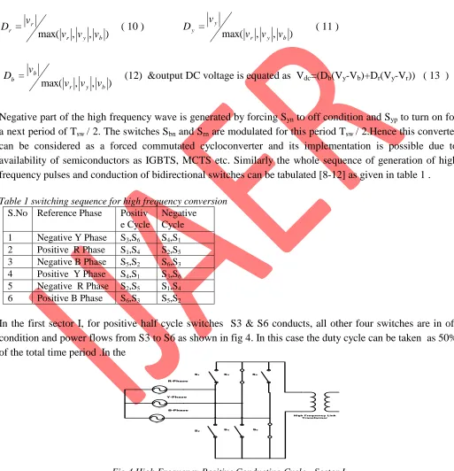
D (12) &output DC voltage is equated as Vdc=(Db(Vy-Vb)+Dr(Vy-Vr)) ( 13 )
Negative part of the high frequency wave is generated by forcing Syn to off condition and Syp to turn on for
a next period of Tsw / 2. The switches Sbn and Srn are modulated for this period Tsw / 2.Hence this converter
can be considered as a forced commutated cycloconverter and its implementation is possible due to availability of semiconductors as IGBTS, MCTS etc. Similarly the whole sequence of generation of high frequency pulses and conduction of bidirectional switches can be tabulated [8-12] as given in table 1 .
Table 1 switching sequence for high frequency conversion
S.No Reference Phase Positiv e Cycle
Negative Cycle 1 Negative Y Phase S3,S6 S4,S1 2 Positive R Phase S1,S4 S2,S5 3 Negative B Phase S5,S2 S6,S3 4 Positive Y Phase S4,S1 S3,S6 5 Negative R Phase S2,S5 S1,S4 6 Positive B Phase S6,S3 S5,S2
In the first sector I, for positive half cycle switches S3 & S6 conducts, all other four switches are in off condition and power flows from S3 to S6 as shown in fig 4. In this case the duty cycle can be taken as 50% of the total time period .In the
AC
AC
AC
S1 S3 S5
S4
S2 S6
High Frequency Link Transformer R-Phase
Y-Phase
B-Phase
Fig 4 High Frequency Positive Conducting Cycle - Sector I
(IJAER) 2011, Vol. No. 2, Issue No. IV, October ISSN: 2231-5152
AC
AC
AC
S1 S3 S5
S4
S2 S6
High Frequency Link Transformer
R-Phase
Y-Phase
B-Phase
Fig. 5 High Frequency Negative Conducting Cycle- Sector I
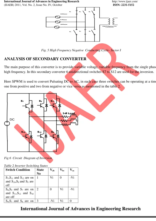
ANALYSIS OF SECONDARY CONVERTER
The main purpose of this converter is to provide variable voltage, variable frequency from the single phase high frequency. In this secondary converter 6 unidirectional switches S7 to S12 are used for the inversion.
Here SPWM is used to convert Pulsating DC to AC, in each case three switches can be operating at a time one from positive and two from negative or vice versa as mentioned in the table 2.
S7
S10
S9 S11
S12 S8
DC
3-Ø Load
Fig 6 Circuit Diagram of Inversion
Table 2 Inverter Switching States Switch Condition State
No
Vab Vbc Vca
S7,S11 and S12 are on and S10,S8 and S9 are off
1 Vi 0 -Vi
S8,S9 and S7 are on and S11,S12 and S10 are off
2 0 Vi -Vi
(IJAER) 2011, Vol. No. 2, Issue No. IV, October ISSN: 2231-5152 and S12,S10 and S11
are off
S10,S8 and S9 are on and S15,S11 and S16 are off
4 -Vi 0 Vi
S12,S10 and S11 are on and S9,S7 and S8 are off
5 0 -Vi Vi
S12,S10 and S11 are on and S9,S7 and S8 are off
6 Vi -Vi 0
S7,S9 and S11 are on and S8,S10 and S12 are off
7 0 0 0
S8,S10 and S12 are on and S7,S9 and S11 are off
8 0 0 0
Out of eight switching states only six switching states are useful for getting required output , the other two switching states 7and 8 are not useful for inversion because in 7th switching state as shown in the table 2 only upper case switches are conducting and in 8th switching state only lower case switches are conducting so that it does not provide closed path in fig 6.
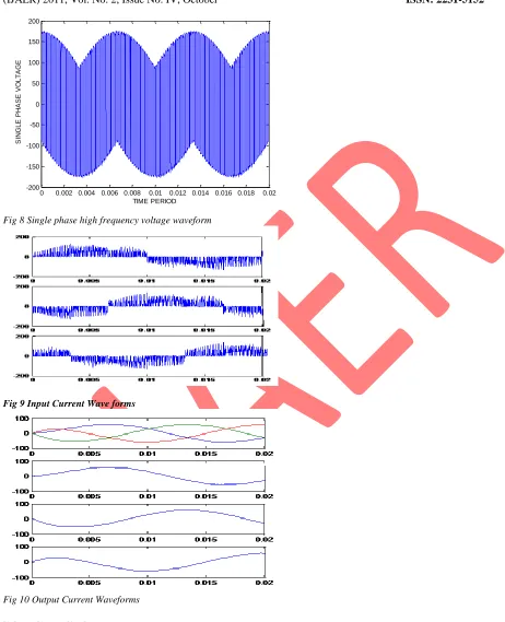
SIMULATION RESULTS
In this Matrix Converter SPWM technique with Hysteresis Controller is used. In this Hysteresis Controller, the output current wave is compared with the input current sine wave and then it is compared with upper and lower hysteresis bands to obtain required pluses to the inverter and hence to achieve sinusoidal current waveform. The performance of this Matrix Converter has been demonstrated by simulations using Mat lab /Simulink. The wave forms of high frequency voltage, input current & output current waveforms are shown in the fig 8, fig 9,fig 10 respectively
(IJAER) 2011, Vol. No. 2, Issue No. IV, October ISSN: 2231-5152
0 0.002 0.004 0.006 0.008 0.01 0.012 0.014 0.016 0.018 0.02 -200
-150 -100 -50 0 50 100 150 200
TIME PERIOD
S
IN
G
L
E
P
H
A
S
E
V
O
L
TA
G
E
Fig 8 Single phase high frequency voltage waveform
Fig 9 Input Current Wave forms
Fig 10 Output Current Waveforms
CONCLUSION
(IJAER) 2011, Vol. No. 2, Issue No. IV, October ISSN: 2231-5152
REFERENCES
1. P. W. Wheeler, L. Empringham, M. Bland “A Utility Power Supply Based on a Four-Output Leg Matrix Converter”, IEEE Transactions On Industry Applications, Vol. 44, No. 1, January/February 2008, pg 174-186.
2. Thiwanka Wijekoon,Pericle Zanchetta “Implementation Of Hybrid AC-AC Direct Power Converter With Unity Power Factor ”,IEEE Transaction On Power Electronics,vol.23,no.4,pg 1918-1928. 3. Fang Gao,M.Renza Iravani “ Dynamic Model Of A Space Vector Modulated Matrix Converter
”,IEEE Transaction On Power Delivery, Vol.22, no.3, July2008, pg .1696-1705.
4. Simon D.Round, Hans Ertl “Novel Three-Phase AC-AC Sparse Matrix Converter” IEEE Transaction On Power Electronics, Vol.22, No.5, September 2007,Pg 1649-1661.
5. Peter Mutschler “A Direct Control Method for Matrix Converters” IEEE Tran on Industrial Electronics, Vol. 49, no. 2, April 2002, pg 362-369.
6. Patrick Wheeler, Jon Clare,Lee Empringham, Maurice Apap and Michael Bland “matrix converters “Power Engineering Journal, December 2002, pg 273-282.
7. R. Erickson, S. Angkititrakul, and K. Almazeedi “A New Family of Multilevel Matrix Converters for Wind Power Applications: Final Report” University of Colorado Boulder, Colorado, NREL Technical Monitor: Alan Laxson, December 2006, pg 15-67.
8. MaÁngeles Martín Prats, L. G. Franquelo “A 3-D Space Vector Modulation generalize Algorithm for Multilevel Converters” IEEE Power Electronics Letters, Vol. 1, No. 4, December 2003, pg 110-115.
9. Lars Helle, Kim B. Larsen, Allan Holm Jorgensen, Stig Munk-Nielsen “Evaluation of Modulation Schemes for Three-Phase to Three-Phase Matrix Converters” IEEE Transactions On Industrial Electronics, Vol. 51, No. 1, February 2004, pg 158-171.
10.Patrick W. Wheeler, Jon C. Clare, Michael Bland “Gate Drive Level Intelligence and Current Sensing for Matrix Converter Current Commutation” IEEE Transactions On Industrial Electronics, Vol. 49, No. 2, April 2002,pg 382-389.
11.LBsz Huber, Duan BorojeviC “Space Vector Modulated Three-phase to Three-phase Matrix Converter with Input Power Factor Correction” IEEE Transactions On Industry Applications, Vol. 31, No 6, November December 1995,pg 1234-1246.