Volume 2, Issue 4, 2015
42 Available online at www.ijiere.com
International Journal of Innovative and Emerging
Research in Engineering
e-ISSN: 2394 – 3343 p-ISSN: 2394 – 5494
Determination of Stress Intensity Factor for a crack in thin
plate under Mode-I loading using Finite Element Analysis
Akash S. Ingle
1, S.J.Parihar
2Department of Mechanical Engineering
Pankaj Laddhad Institute of technology and management studies, Buldana, Maharashtra, India
1Email- [email protected] 2Email- [email protected]
ABSTRACT:
The failure of cracked components is governed by the stresses in the vicinity of the crack tip. The stress intensity factors depend on the geometry of the component and on loading condition. This study is on central cracked plate of a finite length. Basically stress Intensity factor is calculated analytically means by LEFM and computationally. ANSYSTM 14.5 is used as a computational tool. For different values of uniform pressure, stress intensity factor is calculated and then compared with analytical results and good agreement is noted between both approaches. This work is to find the optimal pre-cracked length, in order to eliminate the effect of the SIF and the Fracture toughness.
Keywords: —Stress Intensity Factor (SIF), ANSYS, Linear Elastic Fracture Mechanics (LEFM).Crack tip, Optimal Pre-cracked Length
I. INTRODUCTION
Fracture mechanics is the field of mechanics concerned with the study of the propagation of cracks in materials. It uses methods of analytical solid mechanics to calculate the driving force on a crack and those of experimental solid mechanics to characterize the material's resistance to fracture. Structural design concepts traditionally use a strength-of-material approach for designing a component. This approach does not anticipate the elevated stress levels due to the existence of cracks. The presence of such stresses can lead to catastrophic failure of the structure. In modern materials science, fracture mechanics is an important tool in improving the Mechanical performance of mechanical components. It applies the physics of stress and strain, in particular the theories of elasticity and plasticity, to the microscopic crystallographic defects found in real materials in order to predict the macroscopic mechanical failure of bodies. Fractography is widely used with fracture mechanics to understand the causes of failures and also verify the theoretical failure predictions with real life failures. The prediction of crack growth is at the heart of the damage tolerance discipline. The goal of fracture mechanics is to determine what conditions will create and drive a crack. By understanding the phenomena of fracture engineers can competently design against this particular mode of failure
.
A. FAILURE MODES OF FRACTURE
Consider a cracked plate to distinguish several manners in which a force can be applied on the plate which might enable the crack to propagate. Irwin proposed a classification corresponding to the three situations represented in Fig .1Accordingly, three distinct modes are considered: mode I, mode II and mode III.
In the mode I or opening mode, the body or structure is loaded by tensile forces such that the crack surfaces are pulled apart in the y direction. The deformed surfaces are symmetric with respect to the planes perpendicular to the y-axis and the z-y-axis.
Volume 2, Issue 4, 2015
43
“
Figure 1. Failure modes of fracture”
Finally, in the mode III or tearing mode, the body or structure is loaded by shear forces parallel to the crack front and the crack surfaces slide over each other in the z-direction. The deformed surfaces are skew-symmetric with respect to the plane perpendicular to the z-axis and the y-axis.
B. MATHEMATICAL CALCULATION OF STRESS INTENSITY FACTORS (SIF)
A sample under plane stress conditions, which typically occurs in thin plates, has a highly variable Kc value whereas, a thick sample under plane strain conditions, has a constant value for Kc. Part of Irwin’s revisions of Griffith’s equations was to rewrite the strain energy density in terms of stress because a value for stress is much easier to obtain than a value for strain energy. The resulting equation is:
K
C= β
𝜎
f√ᴨ a
It has unit MPa√𝑚 , where β is a geometry factor, σf is the stress at failure and unit is MPa, and a is the crack
length. Values for β have been determined from equations empirically fitted to the results of numerous fracture tests of varying geometry conducted under constant loading conditions. The equations for different geometries can be found in fracture handbooks. The stress intensity experienced by a material is dependent on the loading conditions and crack geometry.
II. LITERATURE REVIEW
In recent years, considerable efforts have been made for the development of analytical as well as numerical models for the better estimation of crack propagation and fatigue life. The ultimate goal for the researchers who are working in the mechanical design field is to develop structures with high reliability and crack resistant.
Gustavo V. Guinea, Jaime Planas and Manuel Elices developed some considerations related to the influence of element size, element shape, and mesh arrangement on numerical values of KI obtained by the displacement method Mxolisi L. Mbandezi and Raymond B. Mabuza demonstrated the Effect of Variations of Crack geometry on the Stress Concentration Factor in a Thin Plate This study includes a preliminary effort which investigates the effect of variations of crack geometry on the stress concentration factor on a simple thin plate subjected to a constant, uniform, Uni-axial tensile load [6]. M.H. Gozin, M. and AghaieKhafri studied plasticity induced crack closure (PICC) concept. A three dimensional (3D) finite element method (FEM) were used to study the effect of compressive residual stress field on the fatigue crack growth from a hole [2].A. Boulenouar, N. Benseddiq, and M. Mazari illustrate a research on a numerical modeling of crack propagation under mixed mode loading conditions. This work is based on the implementation of the Displacement Extrapolation Method (DEM) and the strain energy density theory in a finite element code. At each crack increment length, the kinking angle is evaluated as a function of stress intensity factors (SIFs) [3].De Xiea and Sherrill B. Biggers developed an interface element to solve 2D progressive crack growth problems under mixed-mode loading. The interface element is developed to calculate the strain energy release rates based on the virtual crack closure technique (VCCT) in conjunction with finite element analysis (FEA) [8].A.B. de Morais developed cohesive zone model for mode I delamination in composite beams. The model is an extension of a beam on elastic foundation analysis similar to the one that led to the well-known corrected beam theory data reduction scheme. In particular, it is demonstrated that the shear foundation considered in most formulations can actually be discarded, thereby allowing a much simpler model implementation [7].Crack free materials do not exist, cracks are everywhere, and they initiate and propagate from the locations of stress and strain concentration The stress intensity factor gives a measure of the intensity of the stress field in the crack tip region.For a through-thickness crack with straight front in a centre-cracked plate of finite thickness, few authors worked to obtain the stress distribution close to the crack front.
III. PROBLEM SPECIFICATION
Cracks often develop in the corners of a structural member due to high stress concentration factor in those areas. If one can calculate the rate of crack growth, an engineer can schedule inspection accordingly and repair or replace the part before failure happens. Moreover, being able to predict the path of a crack helps a designer to incorporate adequate geometric tolerance in structural design to increase the part life. Finite Element analysis of a thin plate with a central crack is done. ANSYSTM Release 14.5 is used to determine the stress intensity factor for a plate. In this analysis, finite
Volume 2, Issue 4, 2015
44 IV.OBJECTIVES
In recent years, the finite element method applied to fracture mechanics has been well developed. There are several studies that have sought to build up the calculation technique and provide a possible and efficient way to construct the FEA model for finite cracked bodies. The objectives for this FEA are listed below:
To determine Stress Intensity Factors for central crack in thin plate for Variable loading conditions. To calculate Stress intensity Factor Analytically by LEFM.
A. Material Properties
For doing the FEA of a plate to determine a stress intensity factor two materials are considered. Materials are steel and aluminium. The material properties for steel and aluminium are described in table 1 [9].
“ Table 1 Material Properties for Steel ”
MATERIAL PROPERTY STEEL
Elastic Modules 210 GPa
Poisson Ratio 0.3
B. Plane 183 Element Descriptions
Finite Element Analysis requires nodes and elements to discretize the given domain into smaller parts. For this FEA here we consider Plane 183 as suitable element. The various features of Plane 183 are described in the below text.
PLANE183 is a higher order 2-D, 8-node or 6-node element. PLANE183 has quadratic displacement behavior and is well suited to modeling irregular meshes (such as those produced by various CAD/CAM systems).
“
Figure 2. Plane 183 Element Description”
This element is defined by 8 nodes or 6 nodes having two degrees of freedom at each node: translations in the nodal x and y directions. The element may be used as a plane element (plane stress, plane strain and generalized plane strain) or as an axisymmetric element. This element has plasticity, hyper elasticity, creep, stress stiffening, large deflection, and large strain capabilities. It also has mixed formulation capability for simulating deformations of nearly incompressible elastoplastic materials, and fully incompressible hyper elastic materials. Initial state is supported. [9].
C. Meshing
Meshing contains nodes and elements. For this FEA no. of elements should be maximum at the crack region with respect to non- crack region. Total no. of elements is 87 and total no. of nodes is 276. The following Fig. 3 contains nodes and elements for the plate. [10].
Volume 2, Issue 4, 2015
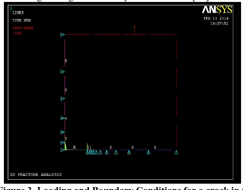
45 D. Loading and Boundary Conditions
For this analysis, we consider a pressure of 100 MPa is applied in vertical direction and symmetry is applied at the vertical and horizontal direction as required for quarter symmetry model. The following Fig. 4 contains the one-fourth geometry of the plate including loading and boundary conditions also [10].
“
Figure 3. Loading and Boundary Conditions for a crack in thin plate”
V. RESULTS AND DISCUSSIONVariation of stress intensity factor KI can be seen in Table II Here both values of Stress intensity factor KI
(i.e., analytical and computational) are compared. The Specific Fracture Toughness (steel) = 50 MPa.√m is obtained for the load 280 N. In Fig. 5 graphs can be seen between both the approaches [11].
“Table2. For Variable Loading Conditions ”
LOADS KI(ANALYTICAL) KI (DEM)
25
4.43
4.51
50
8.86
9.02
75
13.29
13.53
100
17.72
18.04
125
22.15
22.56
150
26.58
27.07
175
31.01
31.58
200
35.44
36.09
225
39.88
40.6
250
44.31
45.12
275
48.74
49.63
300
53.17
54.14
350
62.03
63.17
400
70.89
72.19
Load
0 10 20 30 40 50 60 70 80
25 50 75
100 125 150 175 200 225 250 275 300 350 400
Volume 2, Issue 4, 2015
46 V CONCLUSION
In this project work the ANSYS 14.5 used as a computational tool for the analysis of static fracture mechanics problem. By the use of ANSYS 14.5, K estimated under different loading conditions. In this work as the load increases the stress intensity factor increases simultaneously by the analytical and computational method
.
ACKNOWLEDGMENT
I have taken efforts in this paper. However, it would not have been possible without the kind support and help of many individuals. I would like to extend my sincere thanks to all of them.
I am highly indebted to Prof. Ramdas B. Patthe, for their guidance and constant supervision as well as for providing necessary information regarding the paper. Also I wish to express my sincere thanks to Principal PLITMS Buldana Dr P. M Jawandhiya, and Head of Department Mechanical Engineering Prof. K. R. Sontakke for providing valuable guidance.
REFERENCES
[1] Luay S. M. A. Al-Ansari, ’’Calculating Stress Intensity Factor (Mode I) for Plate with Central Crack: Review and Comparison between Several Techniques of Calculations” Asian Transactions on Engineering Vol. 02 Issue 05, November 2012.
[2] M.H. Gozin, M. Aghaie-Khafri, “2D and 3D finite element analysis of crack growth under compressive residual stress field”, International Journal of Solids and Structures 49 (2012) 3316–3322.
[3] A. Boulenouar, N. Benseddiq, M. Mazari, “Strain energy density prediction of crack propagation for 2D linear elastic materials”, Theoretical and Applied Fracture Mechanics (2013).
[4] Gustavo V. Guinea, Jaime Planas, Manuel Elices,“KI evaluation by the displacement extrapolation technique”,Engineering Fracture Mechanic,(2009)
[5] Manjeet Singh, Satyendra Singh, ”Estimation of Stress Intensity Factor of A Central Cracked Plate”, International Journal of Mechanical Engineering and Technology (IJMET), Volume 3, Issue 2, pp. 310-316, May-August 2012.
[6] Mxolisi L. Mb, andezi, Raymond B. Mabuza, ’’The Effect of Variations of Crack Geometry on the Stress Concentration Factor in a Thin Plate Using Finite Element Method” 18th World Conference on Non-destructive Testing,, Durban, South Africa, 16-20 April 2012
[7] A.B. de Morais, M.F. de Moura b, J.P.M. Gonc alvesb, P.P. Camanho, “Analysis of crack propagation in double cantilever beam tests of multidirectional laminates”, Mechanics of Materials,2006
[8] De Xiea, Sherrill B. BiggersJr,“Progressive crack growth analysis using interface element based on the virtual crack closure technique”,International Journal of Mechanical Engineering and Technology,2006
[9] ANSYS Help Multi-physics utility manual, (2014), Release 14.5., ANSYS TM Inc. Ltd. U.S