227
Available online at www.ijiere.com
International Journal of Innovative and Emerging
Research in Engineering
e-ISSN: 2394 - 3343 p-ISSN: 2394 - 5494
DESIGN AND ANALYSIS OF CRANE HOOK WITH
DIFFERENT MATERIALS
Ejaj R. Khan
a, Vinayak S. Kardile
b, Pravin D. Dhakane
c, Akash P. Gore
d, Bhushan D. Mahajan
e Student of B. E. Mechanical, G.H.Raisoni C.O.E.M.,Chas, Ahmednagara,b.c,dAssistant professor, G.H.Raisoni C.O.E.M., Chas, Ahmednagar e
ABSTRACT:
In this paper the crane hook is designed by analytical method and design is done for the different materials like ASTM grade 60(grey cast iron), high strength low alloy steel, structural steel, SAE 1040 and wrought iron. After the analytical method, by using modeling software (CATIA) the design and modeling of crane hook is done. Then analysis of hook is done in FEA software (ANSYS) with different materials. Stress in existing model is determined by the result obtained from ANSYS. By predicting the stress concentration area, the hook working life increase and reduce the failure stress.
Keywords: Crane hook, FEA software (ANSYS), analysis
I. INTRODUCTION
A Crane hooks are always subjected to failure due to concentration of large amount of stresses which can eventually lead to its failure. Crane hooks are generally used to lift the heavy load in industries and constructional sites [1]. A crane is a machine,
equipped with sheaves, wire ropes or chains and hoist used to lift and move heavy material. Cranes are mostly employed in transport, construction and manufacturing industry. Overhead crane, mobile crane, tower crane, telescopic crane, gantry crane, deck crane, loader crane, jib crane, are some of the commonly used cranes. A crane hook is a device used for lifting and grabbing up the loads by means of a crane. It is basically a hoisting fixture designed to engage a link of a lifting chain or the pin of a cable socket. Crane hooks with circular, trapezoidal, rectangular and triangular cross section are commonly used [8]. So, crane hook
must be designed and manufactured to deliver maximum performance without failure.
The crane hooks are vital components and are most of the time subjected to failure due to accumulation of large amount of stresses, which are ultimately leading to failure. Fatigue of the crane hook is happens due to continuous loading and unloading of crane. If the crack is detected in the crane hook, it can cause fracture of the hook. Due to this there is chances of serious accident. Bending stress, tensile stress, weakening of the hook due to wear, plastic deformation due to overloading, excessive thermal stresses are some of the other reasons of failure [1]. Fig 1. Shows the general diagram of crane hook.
228 A. Material Selection
Structural Steel
High Strength Low Alloy Steel
SAE 1040
Wrought Iron
ASTM Grade 60(Grey cast iron)
II. ANALYTICAL METHOD FOR STRESS CALCULATION
Components having curved portions are frequently subjected to axial or bending loads or to a combination of bending and axial loads. The stress due to curvature become greater and the results of the equations of straight beams when used becomes less satisfactory, with the reduction in the radius of curved portion.
The dimensions for crane hook are taken as follows: 1) Bed diameter
C = x√P, mm
C = 3.12 × 10³
Where, P=load, 49.82 KN
X=constant ranging between 12 to 24.For economic design, x should be as minimum as possible. 2) Throat of Hook (J):2.34 × 103 mm
3) Depth of cross-section area:
h = 70.89 × 103mm
4) Width of cross-section (b):
bi= 46.08 × 103mm
5) Parameter of cross-section:
The inner surface of the cross-section is called ad intrados while the outer surface is called as extrados The parameters of cross-section area are:
Ri= 53.16 × 103mm
R2= 8.86 × 103mm
O1O2= 8.86 × 103mm
6) Radius of intrados and extrados: Ri= 1.56 × 103mm
R0= 110.58 × 106mm
7) Stress in crane Hook:-
The crane hook is a curved bar subjected to: - Direct stress(σd)
- Bending stress(σb)
In curved beam the bending stress distribution is non-linear. In curved beam, the neutral axis does not coincide with the centroid or geometrical axis but is shifted towards the centre of curvature by distance “e”. This is due to non-linear distribution of bending stress.
8) Resultant stress at inner surface of crane hook(σi):
A = 10.19.× 103 mm2
M = 4.14 × 10⁹ N-mm
σd= 4.88 N/mm2
σb = 75.83 N/mm2
𝛔𝐢 = 𝛔𝐝+ 𝛔𝐛
= 𝟒. 𝟒𝟒 + 𝟔𝟓. 𝟖𝟑 𝛔𝐢= 𝟖𝟎. 𝟕𝟏 N/mm2
9) Resultant stress at outer surface of crane hook (σo):
σo = σd+ σbo
σo = P
A+
Mhi
229 The resultant stress at inner surface is additional of tension stress due to direct load and tensile stress due to bending moment. Thus, net stress is addition of two stresses. The resultant stress at outer surface is tensile stress due to direct load and compressive stress due to bending moment. Thus, net stress is different of two stresses.
10) Distance for Trapezoidal Cross-section:-
RN= 6.66
RG= 83.30 × 10³
e = Rg− RN
e = 83.30 × 10³– 6.66
e = 83.29 × 10³
The above equations give the location of neutral axis and the distance between the two for various commonly used cross-sections. The stress concentration
Table 1. Design summary
Material Ultimate
Strength
Direct Stress Bending Stress Resultant
Stress
FOS
High Strength Low Alloy Steel
460 4.88 75.83 80.71 5.69
Structural Steel 440 4.88 75.83 80.71 5.46
SAE 1040 550 4.88 75.83 80.71 6.81
Wrought Iron 300 4.88 75.83 80.71 3.71
ASTM Grade 60 420 4.88 75.83 80.71 5.20
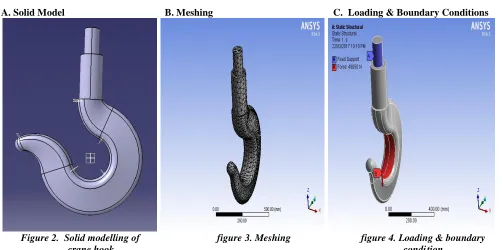
II. ANALYSIS
A. Solid Model B. Meshing C. Loading & Boundary Conditions
230 IV. EQUIVALENT STRESS OF CRANEHOOK
A. ASTM Grade 60(Grey cast iron)
Figure 5. ASTM Grade 60(Grey cast iron)
B. High Strength Low Alloy Steel
231
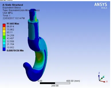
C. Structural Steel
Figure 7. Structural Steel
D. SAE 1040
232
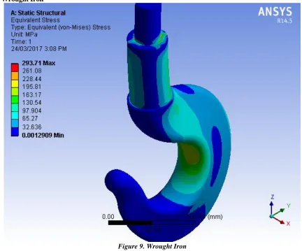
E. Wrought Iron
Figure 9. Wrought Iron
V. RESULT AND CONCLUSIONS
The stress analysis results are calculated from FEA analysis for various different materials such as ASTM grade 60(grey cast iron), high strength low alloy steel, structural steel, SAE 1040 and wrought iron. For all different materials, we will get different results, by keeping the tone are same with different material topology. It is found that the high strength low alloy steel material gives minimum stress which is describe in below table:
Table 2. Results
LOAD (N) Maximum Elastic
Strain
Equivalent Stress Total
Deformation ASTM Grade 60(Grey cast iron) 0.00090792 106.57 0.75889
High Strength Low Alloy Steel 0.00081354 92.21 0.67
Structural Steel 0.00086167 97.665 0.70963
SAE 1040 0.001562 176.23 1.071
233 REFERENCES
[1] Mahesh Solanki 1, Antriksh Bhatt 2, Anilkumar Rathour 3, Smit Thakkar 4, “Weight Optimization in Crane Hook”, IJRDO-Journal Of Mechanical and Civil Engineering ISSN: 2456-1479
[2] Patel Ravin B 1, Patel Bhakti K. 2, Patel Priyesh M 3, Patel Dixit H. 4, “Design and Analysis of Crane Hook with Different Material”, ( International Journal of Advanced Computer Technology (IJACT) ISSN:2319-7900
[3] Govind Narayan Sahu 1, Narendra yadav 2, "Design and Stress Analysis of various cross section of Hook", International Journal of Modern Engineering Research (IJMER) www.ijmer.com Vol. 3, Issue. 4, Jul - Aug. 2013 pp-2187-2189 ISSN: 2249-6645
[4] M. Amareswari Reddy1, M.N.V Krishnaveni2, B. Nagaraju3, M RajaRoy4, "Static Analysis of Crane Hook with T-Section Using ANSYS", International Journal of Engineering Trends and Technology (IJETT) – Volume 26 Number 2- August 2015
[5] Abhijit Devaraj, "Design of a Crane Hook of Different Materials and Stress Analysis Using ANSYS Workbench", International Journal for Research in Applied Science & Engineering Technology (IJRASET Volume 3 Issue VII, July 2015 IC Value: 13.98 ISSN: 2321-9653
[6] Mhashilkar Deepali P.1, Phadnis Swapnil S. 2, " Design and Analysis of EOT Crane Hook", International Journal of Engineering Development and Research © 2016 IJEDR | Volume 4, Issue 1 | ISSN: 2321-9939
[7] Osman Ashraf Ansari 1, Dr. P. Sampath Rao 2, "Design and Analysis of Crane Hook for Load Conditions", International Journal of Mechanical Engineering and Technology (IJMET) ISSN Print: 0976-6340 and ISSN Online: 0976-635
![Figure 1. Trapezoidal Crane Hook [4]](https://thumb-us.123doks.com/thumbv2/123dok_us/8876365.1817099/1.612.256.364.543.707/figure-trapezoidal-crane-hook.webp)