Application of Conditioner Solution by Subsurface Emitters
for Stabilizing the Surrounding Soil
Avi Shaviv
1and Gideon Sinai
2Abstract:Poor uniformity of water application by subsurface drip irrigation has been examined and some explanations are suggested in this paper. Use of soil conditioners for soil structure stabilization around subsurface drip irrigation pipes was suggested by the authors and tested in the laboratory. The conditioners preserve the structure of existing aggregated and may effectively reduce soil clogging. A silt loam soil was uniformly packed in a 1⫻0.8⫻0.15 m box. Two holes were dilled in the box wall through which two emitters were inserted, one for applying solution of soil conditioner and one as a control. Stabilization was achieved by applying two types of polymer solutions differing by their molecular weights through an emitter buried in a silt loam soil. A measured water volume was injected through the emitters into the soil and, after 48 h following irrigation, the box was dismantled. Gravimetric soil moisture content and aggregate water stability were measured in vertical and horizontal distances from the emitter. The highest stabilizing effectiveness was obtained with a volume of 1.5 L polymer solution at 5 g / L concentration, which was applied to the soil at an initial moisture content of 13%. The volume of stabilized soil increased with the volume of applied solution, but the volume ratio of stabilized soil to applied solution decreased with the increase in solution volume. A polymer of relatively low molecular weight was found less effective since a large portion of the solution was consumed by fast penetration into soil aggregates without improving the soil structure. The proposed method offers a simple and easy means for preparing a stabilized soil envelope around subsurface drip irrigation pipes, which may improve the long-term performance and uniformity of the application of these systems. Yet for some of these aspects, further field evaluation is needed, since the results of the study are from a laboratory experiment limited to one soil only.
DOI:10.1061/(ASCE)0733-9437(2004)130:6(485)
CE Database subject headings:Trickle irrigation; Clogging; Soil conditions; Soil stabilization.
Introduction
The subsurface drip irrigation (SDI) method is becoming more acceptable in practice due to some of its inherent advantages (Camp et al. 2000). Microirrigation and particularly SDI can po-tentially “spoon feed” water and nutrients to a crop(Lamm et al. 2001). Such application of water and nutrients requires accurate, steady, and reliable flow rate from the emitters. The long-term efficiency of the SDI method strongly depends on soil conditions at the vicinity of the emitters.
Farmers reported poor uniformity of water application of the SDI systems(Shani et al. 1996; Warrick and Shani 1996). Several explanations have been suggested for the apparent inadequate per-formance of the SDI systems: (1) soil limiting the flow from subsurface emitters;(2)heterogeneity of the soil at the vicinity of subsurface emitters due to plow-type equipment installation tech-niques, which severely disturb the soil around the emitter lines;
and(3)soil plugging due to sediment and subsurface depositional crust formation associated with in-soil particle movement as a result of water flow from the emitters through the soil profile.
Scientists such as Shani and Or (1995), Shani et al. (1996), and Warrick and Shani(1996)who relate the observed decrease in subsurface emitter discharge, to low infiltration rate of the sur-rounding soil, named this phenomenon “soil limiting flow.” They computed a decrease in Christiansen’s uniformity to a value of 0.85 due to spatial variability in soil physical properties, using data from a field in the Arava Valley, Israel. Pressure buildup in the soil, while water could not be easily removed from the sub-surface emitter, caused a decrease in the emitter discharge and affected the uniformity of application.
In the above mentioned research on “soil-limiting flow,” soil properties at the vicinity of subsurface emitters and in the entire field were assumed similar. Two important phenomena were not taken into consideration:(1)soil disturbance caused by the plow’s blade and leg during the installation of the SDI system using the “plowing-in” method and (2) plugging of soil by forming of depositional crusts around the emitter due to in-soil particle movement caused by water flow from the emitter outlet to the soil bulk matrix. Most of the SDI systems are installed in the field at a depth of 20– 40 cm, using the “plowing-in” technique. The emitter tubing is fed into the ground through a slit opening cre-ated by passing the plow blade through the soil. The soil type, soil moisture content, and buried rocks affect the operation of most plows. Spatial variability of these factors affects the extent of soil disturbance and soil structure around the emitter tubing after the installation by the “plowing-in” method. Fry and Spoor (1983) have studied the effect of smearing the sidewalls and bottom of a
1
Associate Professor, Faculty of Civil and Environmental Engineering, Technion-Israel Institute of Technology, Haifa 32000, Israel. 2Associate Professor, Faculty of Civil and Environmental
Engineering, Technion-Israel Institute of Technology, Haifa 32000, Israel (corresponding author). E-mail: [email protected]
trench, by the “plowing-in” method, on the water flow to a drain placed at the bottom of the trench, and found it significant.
The original soil profile is disturbed by the plow blade and leg during the plowing-in method near and above the installed emitter tubing. This soil disturbance has been studied in detail for the evaluation of mole drain plows, which also operate at the same depth as the SDI plows. Godwin et al. (1981) and Spoor and Leeds-Harrison(1999)describe the type of soil disturbance( typi-cal to clay soils) following the passing of a mole plow, which operates at a similar depth as the SDI plow. Vertical fissures are formed by the plow leg at an angle of approximately 45° to the direction of the plow movement. Other cracks in angles of 45° to the horizon are also formed by the plow blade. Most of the satu-rated water flow, in drained clay type soil, occurs through these fissures and cracks. This is true for the first years after installation of SDI system. The disturbed soil slowly settles and the overall soil permeability reduces with time. Taylor and Fausey (1982) reported long-term compaction of backfill soil around drains, which reduces soil hydraulic conductivity. Similar behavior has been observed in mole drainage(clay soils)and is expected in the SDI system, unless the disturbed soil around the emitter laterals has been stabilized, as is suggested here. The objective of such stabilization is to preserve the disturbed, well-structured soil sur-rounding drip laterals after the “plow-in” installation and there-fore to minimize the long-term compaction of this disturbed soil which, if occurs, may adversely effect uniformity of water appli-cation inn the SDI systems.
In-soil movement of soil particles in the soil profile due to water flow is a well-known phenomenon, which occurs mostly in noncohesive, Typic Rhodoxeralfs(U.S. Toxonomy), soils. Sandy loams of about 85% sand and 15% silt and clay(e.g., Arava sandy loam) (Shani et al. 1996)are most likely to be affected by such in-soil particle movement. Less permeable inner soil crust is formed there and are called depositional crusts. Shainberg and Singer(1986)and Southard et al.(1988)measured a reduction in soil hydraulic conductivity of such depositional crusts by 2–3 orders of magnitude compared to that of the soil bulk. It is sus-pected that the soil limiting flow effect reported by Shani et al. (1996) has been affected by such depositional crusts. Hydraulic gradient at the vicinity of the emitter outlet is high, and so is the water flux. It can, therefore, promote silt and clay particle move-ment in the soil. Such movemove-ment may end a small distance away from the emitter where the hydraulic gradient is smaller, thus forming a depositional crust and reducing the emitter discharge. Data of the Arava sandy loam reported by Shani et al.(1996), in which soil limiting flow from the SDI system has been observed, indicate high sensitivity to soil particle movement since it is com-posed of 83% sand, 8% silt, and 9% clay(Typic Rhodoxeralfs).
Drainage scientists use the concept of hydraulic failure gradi-ent (HFG) to indicate the limiting gradient for in-soil particle movement(Stuyt and Willardson 1999). Detailed studies of drain-age filters (envelopes) clogging and siltation of small diameter drain tubes confirm the existence of HFG and its dependence on soil properties. Stuyt and Willardson (1999)suggested an equa-tion which correlates HFG to the soil hydraulic conductivity and to the plasticity index.
It is suggested here that the hydraulic gradients at the vicinity of the SDI emitter outlet are much higher than the HFG of the soil; hence, in-soil particles movement occur near the emitter out-let. In sandy soils, for example, where the plasticity index is very low, the HFG is also very small indicating high soil sensitivity to in-soil particle movement(Stuyt and Willardson 1999). Soil plug-ging due to in-soil particle movement can be minimized using soil
conditioners. A feasible method that includes the use of soil con-ditioners for stabilizing the soil around drains has been suggested by Dierickx and Gabriels(1976), Zaslavsky(1978), and Dierickx and Goossens(1978). This method is based on the stabilization of soils by spraying conditioner solutions on the backfill material and then mixing it thoroughly. Adaptation of such techniques to large soil volumes in the field requires excessive water quantities and effective spraying and mixing technologies.
Good results were obtained by applying conditioners via sur-face drip irrigation (Shaviv et al. 1985). Soil conditioning to a depth of 30 cm was observed in laboratory experiments in which soluble anionic polymers were applied to soil columns by drip irrigation (Shaviv et al. 1987a). The best results were achieved with anionic conditioners of relatively high molecular weight (more than 75,000 Dalton). It was found that the depth of condi-tioned soil was the same as the penetration of the wetting front at the end of application, provided that sufficient conditioner was supplied in the solution(e.g., 4 – 5 g / L)and the antecedent water content was less than that of the field capacity. Soil conditioner application by irrigation water and particularly by drip irrigation presented a new application method which considerably reduced conditioning cost since no extra tillage or mixing were needed (Shaviv et al. 1985). Field soil conditioning experiments showed that results thus obtained were superior to those obtained by spraying and mixing conditioners in the soil(Shaviv et al. 1987b). The objective of this work was to investigate the role of water-soluble soil conditioners injected with water through subsurface emitters in stabilization of soil around SDI emitters.
Experimental Method
A silt loam (12.7% clay content, cation exchange capacity of 9.5 cmol共+兲kg−1; and 0.56% organic matter)was taken from
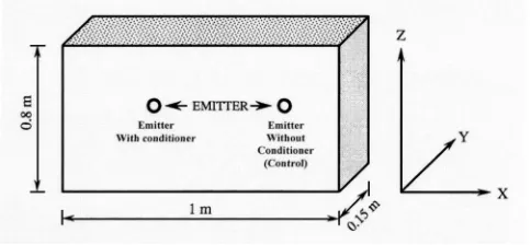
ho-rizon A of a field in the agricultural land in Kissuffim, Northern Negev (typical to semiarid conditions), Israel, air-dried and passed through a 4.76 mm sieve. The soil was then uniformly packed in a 1⫻0.8⫻0.15 m box. Two holes were drilled in the box wall, through which two emitters were inserted at the center of the box, one for applying soil conditioner solutions(Fig. 1)and the other for control without conditioner. The emitter discharge was 0.9± 0.3 L / h.
The experimental setup was used to run several experiments. A measured water volume共V兲was injected through the two emit-ters into the soil, and after 48 h following irrigation, the box was dismantled and the wetted perimeter was marked. Three radii of this wetted parameter were measured(see Fig. 2): P+z, P−z, and
[image:2.612.323.565.38.150.2]Px, namely the vertical distance upward共+z兲, downward共−z兲, and
horizontally 共x兲 from the emitter to the wetted perimeter. The effective wetting radius共Peff兲was defined by
Peff=
P+z+ P−z+ 2Px
4 共1兲
Subsequently, soil samples in two replicates were taken at known distance intervals, vertically upwards(+z axis), vertically downwards(−z axis), and horizontally(x axis)from the emitters (see their locations in Fig. 3). These were used to determine gravimetric moisture content and aggregate water stability using a slight modification of the Yoder (1936) method (Shaviv et al. 1987a). Soil samples were taken at 2 – 5 cm intervals in each di-rection.
The volume of injected water varied from 1.5 to 5 L. Three initial soil–moisture contents were considered: 2.5, 13, and 19%. Two soil conditioner types were applied: LIMA with a molecular weight ⬎75,000 Dalton and LIA with a molecular weight of about 25,000 Dalton(Zaslavsky et al. 1980; Shaviv et al. 1987a, b); and two conditioner concentrations were used; 5 and 10 g / L. These concentrations were selected based on previous findings of Shaviv et al.(1987a), which showed optimal conditioning of the Kissufim silt loam at a conditioner concentration of 4 – 5 g / L. The different treatments are summarized in Table 1.
Results and Discussion
For the evaluation of the stabilizing effect of different conditioner treatments, several parameters were defined. The mean diameter of water stable aggregates D was defined as
D =
兺
i=1 n
Difi 共2兲
where Di= sieve opening(in millimeters); n = number of different sieve screens; and fi= weight fraction of aggregates retained on the ith sieve. Penetration distance (referring to stabilization), R was arbitrarily defined as radial distance from the injection point to the point where the mean diameter of water stable aggregates
共D兲was double the nonstabilized mean diameter D0.
The penetration radius R was measured in three directions, +z, −z, and x(Fig. 2). Effective penetration radius Reff, representing
the average stabilized radius around injection point, was defined by
Reff=
R+z+ R−z+ 2Rx
4 共3兲
The average stabilized area Acin a vertical plane perpendicular to axis y of the line source was defined by
Ac=⌸Reff2 共4兲
Similarly, the average volume of stabilized soil Vc was ob-tained by multiplying the stabilized area Ac by the box width, assuming that the y axis was uniformly wetted after 48 h. The ratio of the stabilized soil volume to the injected water volume was used to express the stabilizing effectiveness of a given treat-ment and defined as
=Vc
V 共5兲
where V = volume of the applied conditioner solution.
Likewise, the ratio of effective penetration radius to the wetted soil共Peff兲radius,, expressed the penetration effectiveness of the soil conditioners
=Reff Peff
[image:3.612.64.270.38.203.2]共6兲
Fig. 2.Illustration of wetted(P vectors)and stabilization(R vectors)
areas of treated soil
[image:3.612.321.561.39.388.2]Since distribution of conditioners surrounding the injection point was radially asymmetric, it was useful to define a distortion ratio as
=R+z R−z
. 共7兲
Finally, the cost effect ratio(CER)was defined as the amount of material(in grams)required to stabilize a volume of 1 L of soil
CER =VC Vc
共8兲
where C = conditioner solution concentration in g/L.
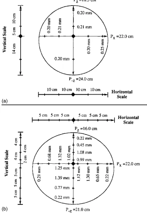
All treatments were analyzed using the above definitions. The mean diameter of water stable aggregates D[Eq.(2)]was used as a measure of aggregate stability [Eq. (2)]. Fig. 3(a) shows the distribution of D in the control soil samples(only water injected). Values of D⬵0.2 mm were found there. Fig. 3(b)shows the sta-bilizing effect of LIMA(Treatment 3 of Table 1), where values of D greater than 1 mm were found at a radius of 7 cm from the injection point. With the radial distance from the injection point D was reduced to 0.2 mm(corresponding to the control)at about 14 and 17 cm in directions +z and −z, respectively. Note the asym-metric vertical distribution of D(due to gravity component of the flow)and the symmetric horizontal distribution. Since symmetric horizontal distribution occurred repeatedly in the treatments, only one horizontal radius of penetration Rxwas reported.
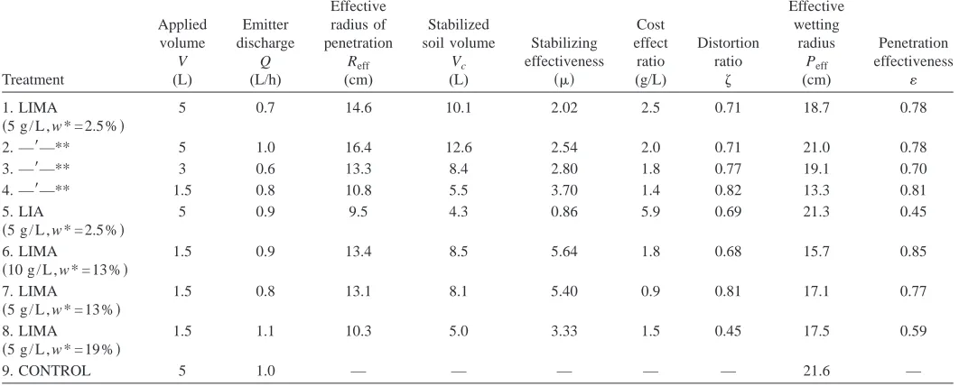
Table 1 summarizes the results obtained with the different treatments. Treatment 2,3,4 repeat treatment 1, but with different volume of applied water and emitter discharge. It is evident(Fig. 4, Table 1) that the stabilizing effectiveness of a given treat-ment was inversely proportional to the injected water volume V. This practically infers that a relatively large soil volume can be conditioned by a small volume of water. Yet the effective penetra-tion radius Reff(and hence, Acand Vc)increased with the injected solution volume V. The effectiveness of soil conditioner penetra-tiondid not correlate well with the volume of injected solution at a given soil moisture content(e.g., Treatments 1–4). The dis-tortion ratio was closest to unity(0.82)when the lowest solution
volume was applied to air-dried soil (Treatments 1–4), and was 0.45 when the conditioner was applied to the wettest soil( Treat-ment 8).
Stabilization results obtained with LIA(low molecular weight) were significantly poorer than those obtained with LIMA. Table 1 shows= 0.86 for LIA compared with= 2.54 for LIMA. Simi-larly, the lowest penetration effectiveness,= 0.45 was measured for LIA. These results conform the observations of Shaviv et al. (1987a)who studied the same soil in column experiments. The findings were attributed to the faster diffusion rate of LIA into the aggregates(a result of lower molecular weight), hence the adsorp-tion(consumption)of more conditioner molecules at the vicinity of the emitter.
[image:4.612.41.572.51.265.2]The effect of the initial soil moisture content on conditioning was also pronounced. The highest(5.4)for a given conditioner concentration was observed for soil with an initial moisture con-tent of 13%, whereas for initially air-dried soil (2.5% moisture) and for soil with 19% initial moisture content, it was significantly lower. The distortion ratio was lowest(0.45), with the wettest Table 1.Summary of Conditioning Results Obtained with Nine Different Treatments
Treatment
Applied volume
V (L)
Emitter discharge
Q (L/h)
Effective radius of penetration
Reff (cm)
Stabilized soil volume
Vc (L)
Stabilizing effectiveness
共兲
Cost effect
ratio (g/L)
Distortion ratio
Effective wetting
radius Peff (cm)
Penetration effectiveness
1. LIMA
共5 g / L , w * = 2.5%兲
5 0.7 14.6 10.1 2.02 2.5 0.71 18.7 0.78
2. —⬘—** 5 1.0 16.4 12.6 2.54 2.0 0.71 21.0 0.78
3. —⬘—** 3 0.6 13.3 8.4 2.80 1.8 0.77 19.1 0.70
4. —⬘—** 1.5 0.8 10.8 5.5 3.70 1.4 0.82 13.3 0.81
5. LIA
共5 g / L , w * = 2.5%兲
5 0.9 9.5 4.3 0.86 5.9 0.69 21.3 0.45
6. LIMA
共10 g / L , w * = 13%兲
1.5 0.9 13.4 8.5 5.64 1.8 0.68 15.7 0.85
7. LIMA
共5 g / L , w * = 13%兲
1.5 0.8 13.1 8.1 5.40 0.9 0.81 17.1 0.77
8. LIMA
共5 g / L , w * = 19%兲
1.5 1.1 10.3 5.0 3.33 1.5 0.45 17.5 0.59
9. CONTROL 5 1.0 — — — — — 21.6 —
Note: w* denotes initial gravimetric moisture content; and **treatment 2,3,4 repeat treatment 1, but with different applied volume of water and emitter discharge.
[image:4.612.322.563.544.706.2]soil and 0.81 and 0.82 for the dryer soils of 2.5 and 13.0% mois-ture contents, respectively. A similar trend was observed with. Results obtained at an initial moisture content of 13% were thus superior in terms of stabilizing effectiveness and more even dis-tribution of the conditioner. These results also confirm the find-ings of Shaviv et al.(1987a), where the highest stabilizing effec-tiveness was found with a similar initial moisture content halfway between air dryness and field capacity. This was explained by the fact that air-dried aggregates were partially destroyed by the wet-ting process, while at the higher water content, the penetration of polymers into the aggregates was inefficient.
The effect of the conditioner concentration is also demon-strated in Table 1. Stabilizing effectiveness values of 5.4 and 5.64 were found for LIMA concentrations of 5 and 10 g / L, respec-tively. The CER thus obtained with the 5 g / L concentration was half of the CER obtained with 10 g / L. These results support the observation made by Shaviv et al.(1987a), who found that con-centrations ranging between 4 and 5 g / L yielded the highest sta-bilizing effectiveness on similar soils. Thus, increasing condi-tioner concentration, from 5 to 10 g / L, had little effect on conditioning effectiveness, whereas the conditioning cost was doubled. The distortion ratio with 10 g / L was lower(0.68)than with 5 g / L(0.81), presumably, due to the higher viscosity of the more concentrated solution.
Field Application and Future Research
The present paper suggests use of soil conditioners to stabilize the soil surrounding subsurface emitters of SDI systems. Results from the preliminary laboratory experiment reported here are promis-ing. A significant increase in stability of soil aggregates was ob-tained by the application of soluble conditioner through a subsur-face emitter.
Field studies should be conducted to evaluate the suggested method. Soil conditioners can easily be applied in the field using conventional chemigation/fertigation equipment, e.g., fertilizer in-jection pumps. Increase in water aggregate stability can be mea-sured using techniques similar to those reported here.
Conclusions
Three reasons for poor uniformity of water application obtained by the SDI are discussed here: (1) soil limiting the flow from subsurface emitter; (2) disturbed soil surrounding SDI laterals, caused by plow blade and leg while the “plowing-in” method of installation is used and may be settled and compacted later, plug-ging emitters outflow and adversely affect uniformity of water application in SDI methods; and (3) plugging of the soil sur-rounding subsurface emitter due to depositional crusts formed by the movement of silt-clay particles in the soil, as a result of water flowing away from the emitters to the soil bulk. The use of soil conditioners to stabilize the soil surrounding the emitter is sug-gested as a feasible technique to improve uniformity of water application in SDI.
A new concept of soil structure stabilization around subsurface drip irrigation pipes has been demonstrated in a bench-scale labo-ratory study. Stabilization was achieved by applying polymer so-lutions through a subsurface emitter buried in a silt loam soil. The highest stabilizing effectiveness was obtained with 1.5 l of LIMA polymer solutions at a concentration of 5 g / L applied to the soil at an initial gravimetric moisture content of 13% (midway
be-tween air dryness and field capacity). The lowest cost effective ratio was obtained with the smallest volume applied at a 5 g / L concentration. A polymer of relatively low molecular weight such as LIA was found less effective, since a large portion thereof was dissipated by fast diffusion into soil aggregates without further improvement of the soil structure.
In order to estimate the real cost of such treatments, further investigation, defining the minimal volume of conditioned soil necessary for efficient functioning of SDI systems, is required.
The proposed method offers simple means of preparing a sta-bilized soil envelope around SDI pipes to improve their perfor-mance. However, it should be further studied, both in the labora-tory and in the field, since the results were obtained with one soil only.
The effect of the soil conditioner on the overall soil permeabil-ity near the emitter outlets can be measured by the methods sug-gested by Shani and Or(1995)and Shani et al.(1996).
Notation
The following symbols are used in this paper: Ac ⫽ average stabilized area共L2兲;
c ⫽ solution concentration共ML−3兲;
CER ⫽ cost effect ratio;
D ⫽ mean diameter of water stable aggregate(L); Di ⫽ sieve opening(L);
D0 ⫽ nonstabilized mean diameter(L);
fi ⫽ weight fraction of aggregates remained on sieve;
Peff ⫽ effective wetting radius(L)
Px,+z−z ⫽ horizontal and vertical(+ = upward, − = downward) distances from emitter, respectively(L);
R ⫽ penetration distance(L); Reff ⫽ average stabilized radius(L);
V , Vc ⫽ volume of applied conditioners and average volume of stabilized soil, respectively共L3兲;
⫽ ratio of effective penetration radius to wetted radius;
⫽ distortion ratio;
⫽ ratio of stabilized soil volume to injected water volume; and
⫽ gravimetric moisture content(m/m).
References
Camp, C. R., Lamm, F. R., Evans, R. G., and Phene, C. J.(2000). “Sub-surface drip irrigation—past, present and future,” Proc., 4th Decen-nial National Irrigation Symp., Phoenix, ASAE St. Joseph, Michi., 363–372.
Dierickx, W., and Gabriels, D.(1976). “Stabilizing backfill of drain pipes and drainage efficiency.” Proc., 3rd Int. Symp. on Soil Conditioning, De Boodt & Gabriels, eds., Vol. 41, State Univ. of Gent, Belgium, 293–300.
Dierickx, W., and Goossens, F. (1978). “Stabilized soil replacing filter material.” Proc., Int. Drainage Workshop, Vol. 25, ILRI.
Fry, R. K., and Spoor, G.(1983). “Electric analogue studies of the influ-ence of soil compaction and smear in the vicinity of a pipe drain on drain performance.” J. Agric. Eng. Res., 28, 207–216.
(2001). “Nitrogen fertilization for subsurface drip irrigation corn.” Trans. ASAE, 44(3), 533–542.
Shainberg, I., and Singer, M. J.(1986). “Suspension concentration effects on depositional crusts and soil hydraulic conductivity.” Soil Sci. Soc. Am. J., 50, 1537–1540.
Shani, U., and Or, D.(1995). “In-situ method for estimating subsurface unsaturated hydraulic conductivity.” Water Resour. Res., 31 (8), 1863–1870.
Shani, U., Xue, S., Gordin-Katz, R., and Warrick, W. A.(1996). “Soil-limiting flow from subsurface emitters, I: Pressure measurements.” J. Irrig. Drain. Eng., 122(5), 291–295.
Shaviv, A., Ravina, I., and Zaslavsky, D. (1985). “Application of soil conditioners by drip irrigation.” Proc., 3rd Int. Drip/Trickle Irrigation Congress, Fresno, Calif.
Shaviv, A., Ravina, I., and Zaslavsky, D.(1987a). “Application of soil conditioner solutions to soil columns.” Soil Sci. Soc. Am. J., 51, 431– 436.
Shaviv, A., Ravina, I., and Zaslavsky, D.(1987b). “Field evaluation of application methods of a soluble anionic conditioner.” Soil Tillage Res., 9, 151–160.
Southard, R. J., Shainberg, I., and Singer, K. M.J.(1988). “Influence of electrolyte concentration on the micromorphology of artificial deposi-tional crust.” Soil Sci., 145, 278–288.
Spoor, G., and Leeds-Harrison, P. B.(1999). “Nature of heavy soils and potential drainage problems.” Agricultural drainage, R. W. Skaggs and J. van Schilfgaarde, eds., Agron Mon. 38, ASA, CSSA, and SSSA, Madison, Wis., 1051–1081.
Stuyt, L. C., and Willarson, L. S.(1999). “Drain envelopes.” Agricultural drainage, R.W. Skaggs and J. van Schillgaarde, eds., Agron Mon. 38, ASA, CSSA, and SSSA, Madison, Wis., 927–962.
Taylor, G. S., and Fausey, N. R.(1982). “Backfill alterations and drainage of clay soils.” Proc., 4th ASAE National Drainage Symp., Chicago. Warrick, A. W., and Shani, U.(1996). “Soil-limiting flow from
subsur-face emitters, II: Effect on uniformity.” J. Irrig. Drain. Eng., 122(5), 296–300.
Yoder, R. E.,(1936). “A direct method of aggregate analysis of soils and study of physical nature of erosion losses.” Amer. Soc. Agron. J.,28, 337–351.
Zaslavsky, D.(1978). “Definition of the drainage filter problems and a possible use of soil conditioners.” Proc., Int. Drainage Workshop, Wesseling, ed., Wageningen, Netherlands, 340–353.