a
Corresponding author: [email protected]
Evaluation of Steadiness and Drop Size Distribution in Sprays Generated
by Different Twin-Fluid Atomizers
Matouš Zaremba1,a, Marek Mlkvik1 Milan Malý1, Jan Jedelský1 and Miroslav Jícha1
1
Brno University of Technology, Faculty of Mechanical Engineering, Department of the thermodynamics and environmental engineering, Technická 2896/2, 616 69 Brno, Czech Republic
Abstract. Twin-fluid atomizers underwent a significant development during the last few decades. They are common in many industrial applications such as fuel spraying, melt atomization and food processing. This paper is focused on the evaluation of four different twin-fluid atomizers. The aim is to compare the quality of sprays generated by various atomizers with similar dimensions and in the same operating regimes. A phase-Doppler anemometry (PDA) and particle image velocimetry (PIV) were used to measure spray characteristics such as velocity and size of the droplets. Measured data were used to compare droplet size distribution and to evaluate steadiness of the spray. Visualisations were made to support measured data and to clarify the principles of primary atomization and its influence on the spray.
1 Introduction
Twin-fluid atomizers are one of the most universal atomizers in industry. They are designed for various applications, for example: atomization of highly viscous and waste fuels, atomization of melts, food processing industry, powder drying and others. Due to the various fields of usage many different designs of twin-fluid atomizers were developed. Generally, these atomizers can be divided into two categories: atomizers with internal or external mixing of phases. The external mixing atomizer operates on the principle of generating relatively high velocity difference between gas and liquid. The velocity difference helps to disintegrate liquid [1]. Atomizers with internal mixing are characterized by the internal mixing chamber where usually two phases are mixed. Two-phase flow is created inside the atomizer and it is pushed downstream through the atomizer and disintegrates after passing the exit orifice. Liquid is shattered by the rapidly expanding gas [2-4]. This paper is focused on four different twin-fluid atomizers designed for spraying of light heating oil.
Atomizers were examined mostly on the basis of input parameters such as operating pressure, gas to liquid ratio (GLR), dimensions of the nozzle, liquid physical properties and ambient conditions and its influence on the resulting spray quality [3-5]. Majority of studies which deal with twin fluid atomizers are focused directly on one type of atomizer. However, a comparison of more different designs of twin-fluid atomizers has not been sufficiently described yet. Comparison can only be made under
the assumption of using the same methodology, the same liquids and the same operating conditions.
We assume an application of atomizers for fuel spraying for combustion processes. One of the most important parameters of these sprays is droplet size distribution. The size of droplets in the spray is often described using the Sauter mean diameter [2]. Another important aspect of the spray quality is the steadiness [6]. Unsteadiness has a negative impact on the noise level of the combustion. It raises the load of the combustion chamber and it causes problems in the burner starting sequence [7]. Workers Edwards and Marx [8] have published a method designed for effervescent sprays for evaluating the steadiness of the spray using inhomogeneous Poisson statistics and time dependent point measurements in sprays. Several workers used this method afterwards for spray examination, for instance: [7-11]. Mostly for evaluation of the influence of operational conditions, physical properties of the atomized liquid and dimensions of the atomizer on the spray unsteadiness. The aim of this paper is to use these characteristics of sprays and compare four different twin-fluid atomizer under the same operating conditions and with the same methodology.
2 Materials and methods
All presented data was acquired by cold testing of twin fluid atomizers in the Spray laboratory at the Energy department, Faculty of Mechanical Engineering, Brno University of Technology.
C
Owned by the authors, published by EDP Sciences, 2015
2.1 Test bench
Examined atomizers were operated on a test bench equipped with fuel and air supplies. Light heating oil was used as an atomizing fuel. Density of the oil is 874 kg·m-3 and dynamic viscosity is 0.0185 kg·m-1·s-1 at 20 °C. Oil was pushed from a pressure fuel tank through a filter, regulation valve and mass flow meter into an atomizer. Compressed air was used as atomizing gas. It was taken from the central pressurized line. Air was pushed through a filter and regulation valve into the atomizer. Detailed description of the test bench can be found in [12].
2.2 Phase-Doppler Analyser
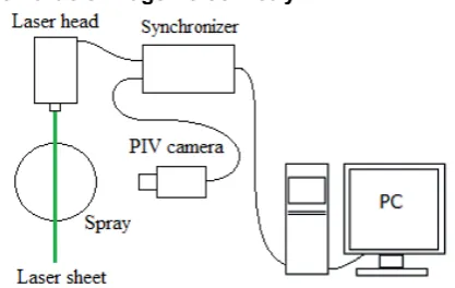
Figure 1 Schematic layout of the PDA system, top view.
A 2D fibre based phase-Doppler anemometer (PDA) by Dantec Dynamics was used for measuring the droplet velocity (in radial and axial direction relative to the axis of the spray) and droplet size. The system measures time resolved data which enables us to make their temporal analysis. Measurements were performed in axial distance of 100 mm from the exit orifice of an atomizer in one radial profile. Schematic layout can be seen in figure 1. This particular distance was chosen due to the fact that in this distance fully developed spray is expected [5]. This means that we assume finished atomization processes: primary and secondary atomization. Detailed description of the measuring system can be found in [12].
2.3 Particle Image Velocimetry
Figure 2 Schematic layout of the PIV system, top view.
A PIV system was used to visualize the emerging two phase flow in the region near to the exit orifice of the atomizer. Spray images were captured by a CCD PIV camera (TSI PIVCAM 13-8) with attached Nikon 60 mm lens. The examination area of interest is of dimensions 41 × 50 mm which gives resolution of 40 μm/pixel. A series of images was captured and a characteristic image of spray pattern is displayed in figure 4. Detailed description of the PIV system can be found in [13].
2.4 Atomizers
Four different twin-fluid atomizers were examined in this paper. They were operated at low pressure 0.07 MPa and three regimes of GLR from 2.5% to 10%. The operating conditions can be found in table 1.
The principle of how air or liquid is injected into the mixing chamber will be described in the following paragraphs.
Table 1. Operating condition at the pressure of 0.07 MPa.
Atomi
zer GLR (%)
Mass flow rate (kg/hour) LHO Air
CFT
2.5 4.30 0.11 5 3.04 0.15 10 1.88 0.19
OUIG
2.5 4.08 0.10 5 2.65 0.13 10 1.70 0.17
OUIL
2.5 3.75 0.09 5 2.65 0.13 10 1.72 0.18
Y
2.5 3.49 0.09 5 2.54 0.13 10 1.68 0.17
2.4.1 CFT atomizer
2.4.2 Outside-in gas effervescent atomizer
A standard outside-in gas effervescent atomizer (OUIG) was examined. This atomizer works on a principle of injecting pressurized air into a liquid stream through a set of aerator holes. A schematic layout of the atomizer is presented in figure 3b. Inside the atomizer is a mixing chamber where fuel is mixed with air. Ideally small bubbles of air are created inside the liquid stream, so called bubbly flow [14]. This regime is typical for values lower than 5% of GLR [3, 5]. Higher values lead to change of internal flow pattern from bubbly flow to an annular flow. This pattern is characterized by the liquid mass concentrated on the walls of the atomizer and air core in the centre of the flow. A two phase flow is then pushed downstream to the exit orifice and it is disintegrated when it passes through the exit orifice [17]. The character of the two phase flow depends mainly on the GLR and on the dimensions of the mixing chamber [3, 5, 18]. Therefore differences between examined operating regimes are expected.
2.4.3 Outside-in liquid effervescent atomizer
The design of this atomizer corresponds to the design of the previously described standard OUIG atomizer. The only difference is that fuel and air port entries are switched as it can be seen in figure 3c. The liquid is injected into gas stream into mixing chamber through a set of aerator holes.
2.4.4 Y-Jet atomizer
As the name suggests, this atomizer works on the basis of injecting fuel into the air stream under a particular angle, see figure 3a. According to [19-21] the internal flow regime depends on liquid and gas mass flows, and GLR and dimensions of the mixing chamber. The atomization process is divided into three phases according to [21]. Firstly, when the liquid stream reaches the air jet inside the mixing chamber, it is partially disrupted. This mode is called direct collision. Secondly, the mixture flows along the mixing chamber and annular liquid film is formed. The distorted air stream is straightened up in the axial
direction, and some drops are generated by the shearing air flow. The internal flow inside the mixing chamber has annular character for most regimes. Thirdly, the mixture reaches the exit orifice and liquid film is disintegrated into ligaments and then into drops by the expanding air core. According to [21], the droplet size distribution depends on the liquid film thickness inside the mixing chamber which is influenced by the gas and liquid momentum ratio.
2.5 Steadiness of the spray – measurement method
According to the theoretical framework presented by workers Edwards and Marx [8] it is possible to evaluate steadiness of the spray using time-based multipoint statistics of sprays. Steady spray is defined as the spray whose interparticle arrival time distribution obeys inhomogeneous Poisson statistic. Consequently, unsteady spray is defined as spray whose interparticle arrival time distribution does not obey inhomogeneous Poisson statistics. Detailed description of the method is presented in [22]. The level of unsteadiness is expressed with value
which represents unsteadiness of the spray. This value was calculated using time resolved data from PDA system.
2. Integral Sauter mean diameter
As it was mentioned, examined atomizers were originally designed for spraying of highly viscous liquid fuels. Regarding applications in combustion processes it is important to know a droplet size distribution of the whole spray. The most common parameter which describes the droplet size distribution in sprays is Sauter mean diameter (D32). This value determines droplet distribution in one particular point in the spray. For the description of the whole spray using one specific value workers Jedelský et al. [5], deducted an intergal Sauter mean diameter (ID32) which describes global spray quality with only one number. Detailed description of the value of ID32 can be found in [5].
3 Results and discussion
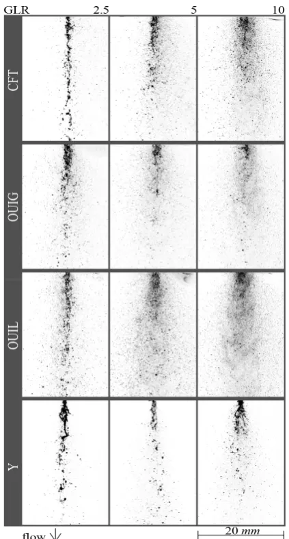
Images of examined sprays are presented in figure 4. A direct impact of the operating regime on the spray
Fi Schematic layout of the PIV system. 6
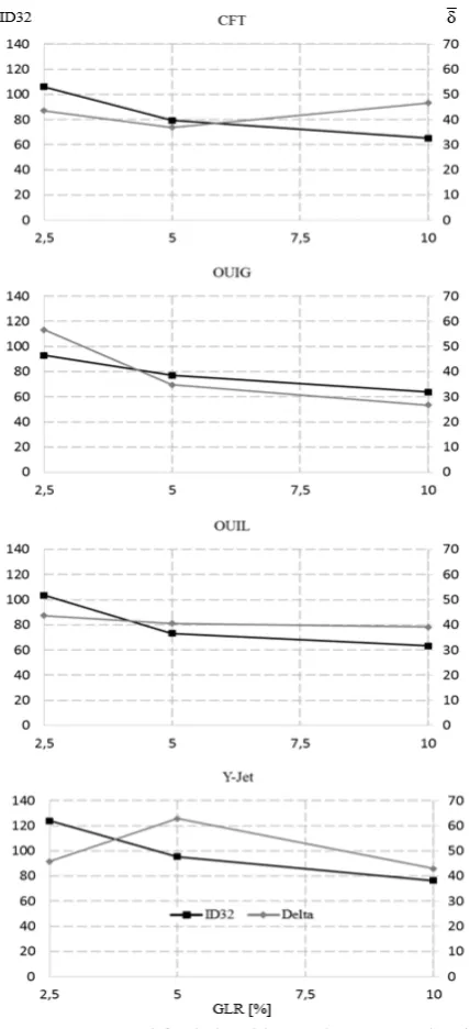
development in near-atomizer area can be seen. At the lowest value of GLR (2.5%) it is shown that all atomizers produce large structures – ligaments. The emerging two phase flow is relatively narrow and dense for all atomizers. Comparing between atomizers it can be stated that the Y-Jet atomizer produces the longest ligaments which lead to large droplets. This is in agreement with previous works [19, 21]. Also the value of ID32 in figure 5 proves this statement. According to [21] the amount of fuel inside the mixing chamber influences the thickness of the annular liquid sheet which has a direct impact on the diameter of ligaments and consequently on the drop size distribution.
The CFT atomizer performs similarly. A disrupted liquid stream can be seen for GLR = 2.5%. The majority of the mass is concentrated in the centre of the spray. The ligaments are presented even in the bottom of the figure which points to the unfinished breakup process. As expected, the CFT atomizer has the second highest value of ID32 in this regime. In contrast, the OUIG and OUIL atomizers produce relatively well disintegrated spray even in the region near the exit orifice of the atomizers. Even though, they have the same diameter of the exit orifice as the CFT. It should be noted that these atomizers operate in the same operating regime, moreover with similar liquid mass flows according to table 1. For that reason we assume that the mixing process has a direct impact on the spray performance especially in the low GLR regimes. The different spray patterns influence the value of ID32. The smallest droplets are produced by the OUIG atomizer in this particular regime, see figure 5. This corresponds to the previous works on the effervescent atomizer where it was proved that at low GLR regimes, during which the atomizer operates at bubbly internal flow, the atomizer is able to perform small droplet distribution thanks to the specific breakup process [3, 4].
When we inspected images from regimes of GLR = 5% we observed that spray is more dispersed. Significant difference of the spray pattern can be seen for the Y-Jet atomizer which again produces a narrow spray with large ligaments. In comparison with previous regime, the ligaments are smaller. This corresponds to the value of ID32 as can be seen in figure 5. The drop of ID32 value is present for all atomizers as was expected. The amount of atomizing air was increased as well as the potential energy available for the atomization. The atomizing air reduces the thickness of liquid structures and increases its velocity.
The difference of the value of the ID32 from 5% to 10% of GLR is considerably lower than difference from 2.5% to 5%. When we inspect a classic effervescent atomizer (OUIG) the ID32 difference between 2.5% and 5% is caused by the change of the internal flow pattern. From bubbly to slug or annular [1, 23, 24]. Which also means there is a change in the breakup mechanism [25]. The change from 5% to 10% means that the internal flow patterns might remain the same. But the amount of the air mass flow is increased. Thus, only air mass flow is responsible for the change of ID32 value. The internal two-phase flow patterns in CFT and OUIL atomizers were not examined properly before. So it can be only
assumed that the above mentioned principle related to the OUIG atomizer is present also in the other two atomizers.
Figure 4 Typical images of the spray patterns in area near to the atomizer.
Regimes at GLR = 10% are characterized by well dispersed spray in whole image. Even the Y-Jet atomizer produces relatively well dispersed spray but compared to the other atomizers, ligaments and other liquid structures are still present. As it was mentioned in [21] the Y-Jet atomizer works on the principle of the annular liquid sheet disintegration. The liquid is accelerated inside the mixing chamber by the high speed flowing air. The first pressure drop of the liquid is after entering the mixing chamber, see figure 3. The second pressure drop comes after mixture passes through the exit orifice. The conversion of an initial potential energy to the kinetic energy is thus divided into two steps. This leads to the lower pressure drop at the exit of the atomizer. That is why, liquid structures and ligaments are still present in the regimes of GLR = 10%. Again, the value of ID32 is the highest for this atomizer in contrast to the other three atomizers.
Figure 5 ID32 and relationship varying GLR value for each atomizer.
The CFT atomizer produces the most unstable spray at the highest GLR value. With decreasing GLR to 5% the steadiness of the spray increases and with further decrease in GLR, spray steadiness decreases. Thus we can observe local minimum of the spray unsteadiness at 5% GLR.
The value of for atomizers OUIG and OUIL increases as the GLR decreases as expected [9]. For OUIG atomizer periodical pulsations were observed as can be seen in figure 6 which supports the results from values of . In this figure separated clouds of dots can be observed. Each cloud represents one pulse of liquid. It was detected as several droplets with velocity varying from about 2 m/s to 16 m/s.The period of the pulsating regime is approximately 110 ms. This behaviour might be attributed to the internal flow pattern. As it was mentioned in [7, 8, 9], effervescent sprays are inherently unstable and internal two-phase flow patterns might lead
to the highly unsteady behaviour of the spray. For instance, the slug flow is one of the most unstable patterns. The observed pulsating regime is a special case. For other atomizers similar behaviour not yet been observed.
The Y-Jet atomizer performs differently. The most unstable regime is for GLR = 5%. Then the value of decreases for both GLRs; 2.5% and 10%. No pulsating regime was observed as it was mentioned for the OUIG atomizer. According to figure 4 for Y-Jet atomizer, we might assume that spray for 2.5% is a special case where the emerging liquid looks like disturbed liquid stream which produces large liquid structures. Thus the Poisson statistic might not be a proper tool for evaluation of the spray stability. Moreover, the data rate for this particular regime was nearly half of the data rate for the other three atomizers (data rate for the OUIL atomizer was around 1 kHz and for the Y-Jet atomizer it was 470 Hz). When we inspect the most unstable spray (Y-Jet atomizer at 5% of GLR) we can observe that the droplet axial velocity has bimodal distribution.
Figure 6 Time dependency of droplets axial velocity for OUIG atomizer at 2.5% of GLR in the centre of the
spray.
Figure 7 Time dependency of droplets axial velocity for Y-Jet atomizer at 5% of GLR in the centre of the spray.
4 Conclusions
The aim of this paper was to evaluate the quality of the spray considering the size of droplets and steadiness. These two factors are important for several reasons especially for the applications in industrial processes. Generally, it can be stated that the Y-Jet atomizer produces the largest droplets in all regimes. One assumption for this is that liquid in Y-Jet atomizer experiences two pressure drops and thus the final pressure drop is not as high as for other atomizers which results in larger drops. Moreover, the stability of the Y-Jet atomizers is poor which supports results of the ID32 value. Unusual behaviour can be seen for GLR = 2.5% which was attributed to the unusual spray pattern and low data rate.
Atomizers OUIG and OUIL perform similarly. Their stability increases with the value of GLR and the value of ID32 increases as value of GLR decreases as expected. The main difference between these atomizers is in the stability. The OUIG is more unsteady at regime of GLR = 2.5% where periodical pulsating spray was observed. Regimes for 5% and 10% GLR are more stable for the OUIL atomizer. It should be pointed out that these two atomizers have the same dimensions but the air and liquid ports are inversely connected. The newly developed CFT atomizer behaves in a similar way as the OUIL and OUIG atomizer for the ID32 values. The main difference can be found in stability. The local minimum is for GLR = 5% whereas the maximum value of is for 10% of GLR.
Presented results show that for the classic construction of effervescent atomizers (OUIG and OUIL) expected behaviour was found. The other two atomizers perform differently. This might be attributed to the fact that they operate with different liquid breakup mechanisms. The breakup mechanism was examined before only for the OUIG and Y-Jet atomizer but CFT and OUIL atomizers are still in development. The stability of the Y-Jet and CFT atomizers has not been examined before as well. Thus comparison with previous results is not possible. Deeper knowledge of the mixing and breakup processes should be obtained in order to be able to explain such a complex process as it is in the case of these atomizers.
Acknowledgements
Authors acknowledge financial support from project No. P101/11/1264 funded by the Czech Science Foundation and NETME Centre, regional R&D centre built with the financial support from the Operational Programme “Research and Development for Innovations” within the project “NETME Centre (New Technologies for Mechanical Engineering)”, Reg. No. CZ.1.05/2.1.00/01.0002 and, in the follow-up sustainability stage, supported through NETME CENTRE PLUS (LO1202) by financial means from the Ministry of Education, Youth and Sports under the “National Sustainability Programme I”.
References
1. LI, Z. H., Y. X. Wu, C. R. Cai, H. Zhang, et al., Fuel, 97, 306-314, (2012).
2. Lefebvre, A. Atomization and Sprays. Edtion ed.: Taylor & Francis, (1988), ISBN 9780891166030. 3. Sovani, S. D., P. E. Sojka AND A. H. Lefebvre
Effervescent atomization. Progress in Energy and Combustion Science, 27, 483-521, (2001).
4. Konstantinov, D., R. Marsh, P. Bowen And A. Crayford, Atomization and Sprays, 20, 525-552, (2010)
5. Jedelský, J., M. Jícha, J. Sláma and J. Otáhal, Energy & Fuels, 23, 6121-6130, (2009).
6. Lefebvre, A. H. GAS Turbine Combustion, Second Edition. Edtion ed.: Taylor & Francis, (1998). ISBN 9781560326731.
7. Jedelský, J. and M. Jícha, Atomization and Sprays, 18, 49-83, (2008).
8. Edwards, C. F. and K. D. Marx Atomization and Sprays, 5, 435-455, (1995).
9. Luong, J. T. K. and P. E. Sojka, Atomization and Sprays, 9, 87-109, (1999).
10. Liu, M., Y. Duan and T. Zhang, Experimental Thermal and Fluid Science, , 34, 657-665, (2010). 11. Liu, M., Y. Duan, T. Zhang and Y. Xu Experimental
Thermal and Fluid Science, 35, 190-198, (2011). 12. Jedelský, J., M. Zaremba, M. Malý and M. Jícha,
EPJ Web of Conferences. 67, (2014).
13. Zaremba, M., M. Malý, J. Jedelský and M. Jícha, AIP Conference Proceedings, 1608, 272-275, (2014). 14. Chin, J. S. and A. H. Lefebvre, Journal of
Engineering for Gas Turbines and Power, 117, 266-271, (1995).
15. Ferreira, G., J. Aantonio Garcia, F. Barreras, A. Lozano, et al., Fuel Processing Technology, 90, 270-278, (2009).
16. Tamaki, N., M. Shimizu & H. Hiroyasu, Proc. ILASS-Europe, 412–417, (2004).
17. Chin, J. S. and A. H. Lefebvre, Atomization and Sprays, 3, 463-475, (1993).
18. Sen, D., M. A. Balzan, D. S. Nobes and B. A. Fleck, Journal of Visualization, 17, 113-122, (2014). 19. Mullinger.PJ and N. Chigier, Journal of the Institute
of Fuel, 47, 251-261, (1974).
20. Pacifico, A. L. and J. I. Yanagihara, Journal of the Brazilian Society of Mechanical Sciences and Engineering, 36, 13-22, (2014).
21. Song, S. and S. Lee, Atomization and Sprays, 6, 193-209, (1996).
22. Jedelský, J., Jícha, M.; Beinstein, Z., In Proceedings of 11th Triennial International Conference on Liquid Atomization and Spray Systems.1. Denver, CO: University of Denver, s. 1-6, (2009).
23. Huang, X., X. Wang and G. Liao, Journal of Visualization, 11, 299-308, (2008).
24. Lefebvre, A. H. and J. S. Chin, Atomization and Sprays, 3, 463-475, (1993).