Performance Analysis of Optimization
Techniques and Intelligence Techniques for
Speed Control of DC Motor
Santosh Kumar Suman1, Vinod Kumar Giri2
Research Scholar, Department of Electrical Engineering, Madan Mohan Malviya University of Technology, India 1
Professor, Department of Electrical Engineering, Madan Mohan Malviya University of Technology, India 2
ABSTRACT:Aim of This paper Performance Analysis of controllers such as PID controller, fuzzy logic controller and G.A based PID for speed control of DC motor. Simulation results have established that the use of Self Tuned fuzzy logic and GA-PID results in a good dynamic behaviour of the DC motor, a great speed tracking with lowest overshoot, gives better performance and high forcefulness than those obtained by use of the other controller. The DC motor is broadly used in many applications like steel mills, electric trains, cranes and much more. In this paper a separately excited dc motor using MATLAB modelling has been outlined whose velocity might be examined utilizing the Proportional, Integral, Derivative (KP, KI , KD) addition of the PID controller. Since, established controllers PID are neglecting to control the drive when weight parameters be likewise changed The principle point of this paper is to dissect the execution of Optimization techniques viz. The Genetic Algorithm (GA) for improve PID controllers parameters for speed control of DC motor and list their points of interest over the traditional tuning strategies. The output speed error and its derivative as feedback damping signals. Through this simulation the performance of the GA-PID is compared with that of the Fuzzy Logic controller. The GA-GA-PID optimized but FLC gives better performance in terms of delay time, peak time, steady state error.
KEYWORDS:DC motor, PID controller, Optimization techniques Genetic algorithm (GA), Objective function, IAE, Fuzzy logic.
I. INTRODUCTION
progressions amid subordinate activity) and PI enhances execution of consistent state reaction (i.e. lessen enduring state balance amid fundamental activity or law), mix of two might be utilized to advance general time reaction of the framework. Notwithstanding this, PID controllers have exceptionally uncomplicated control structure and are less expensive [4].The target of this paper is to investigate the execution of Genetic Algorithm (GA) for ideal tuning of PID controllers parameters and count their points of interest over the ordinary tuning systems Genetic Algorithms (GA) are versatile heuristic inquiry taking into account transformative thoughts of normal choice and hereditary qualities. Hereditary Algorithms are powerful and clever decisions under the most favourable conditions arrangement among the space of every attainable arrangement. The Genetic Algorithms were utilized to assess the ideal PID controller addition values where performance indices, IAE were utilized as the objective function. It was tentatively established that the Integral of Absolute Magnitude of the error (IAE) execution foundation delivers the best PID controller when contrasted and other execution paradigm. The proposed procedures wereconfirmed utilizing a third order physical model of plant as DC motor (separately excited dc motor) where tuning calculations were driven for the most part by the obtained framework information and the coveted execution parameters determined by the client are effectively fulfilled. Resultant upgrades on the stride reaction conduct of DC motor speed control framework are appeared for two cases. This paper is composed as takes after: system modelling of DC motor is displayed in Section II, PID controller brief describe in section III, brief prologue to genetic algorithm is talked about in Section IV, main work of this paper describe in section V as a tuned methodology and last two Section VI and VII individually describe simulation result and conclusion of this paper speed control of dc motor.
II. SEPARATRLYEXCITEDDCMOTOR
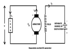
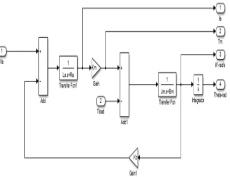
The SEDC motor drive system through armature control and the voltage apply to armature of the motor is familiar without realignment the voltage functional to the field. Figure.1. shows a separately excited DC motor equivalent model (SEDC). It is assemble of the circuit model of dc motor using MATLAB/Simulink as shown in Figure.2.In this a special case through the supply provided a separately to armature winding and field winding. The main a different or distinct form in these types of dc motor is with the main purpose of the field winding in does not flow the armature current because, the field winding is agitated from a separate external source of dc current. DC motors gives outstanding control of speed for motors require of their main parameters such as position, speed, acceleration etc [5]. DC motor is a high performance motor drive. The dc motor drive is based on the principal, when a current carrying conductor is to be found in a magnetic fields, it experience a force which has a tendency to move. This is known as motoring action or rotating function, when magnetic field and electric field work together they produce a mechanical force.
Circuit Model of DC Motor
Figure 1:Separately Excited DC Motor.
aa a a a b
di (t)
V t
R i (t) L
e (t)
dt
(1)b b
e (t)
K . (t)
(2)m m a
m m m
d
ω( )
T (t)=J .
B .
ω(t)
dt
t
(4)m
2 2
a a m a m a m a m b T
K
ω(s)
=
V (S)
L .J s +(R .J +L .B )S +(R .B +K .K ).S
(5)m
3 2
a a m a m a m a m b T
K
θ(s)
=
V (S)
L .J s +(R .J +L .B )S +(R .B +K .K ).S
(6)1
θ(s)= ω(S)
S
(7)Where
R = armature resistance (Ω- ohm).
L = armature inductance (H-henry). = armature current (A).
V (t)= armature voltage (V). = back emf (V).
ω = angular speed (rad/s). = motor torque (N m).
θ = angular position of rotor shaft (rad). = rotor inertia (kg m2).
= viscous friction coefficient ( s/rad). = motor torque constant (Nm/A). = back emf constant (V s/rad).
Simulink Modelling of Dc Motor
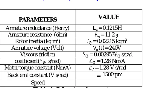
PARAMETERS VALUE Armature inductance (Henry) L = 0.1215H
Armature resistance (ohm) R = 11.2 Ω Rotor inertia (kg m2) = 0.02215 kgm2 Armature voltage (Volt) V (t)= 240V
Viscous friction = 0.002953 s/rad coefficient( s/rad) = 1.28 Nm/A Motor torque constant (Nm/A) = 1.28 V s/rad Back emf constant (V s/rad) ω= 1500rpm
Speed
Table 1: DC motor of parameters
III.PIDCONTROLLER
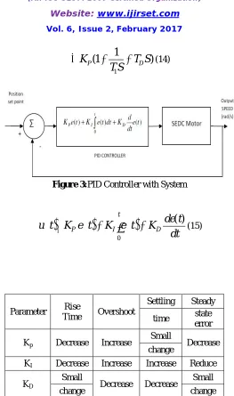
PID controllers have been for the most part used for control framework. The most essential step for applying the PID controller is the tuning of its parameters. The tuning handle needs an extensive measure of time and effort. In the most sceptical situation, the awful tuning prompts a poor execution of the controlled system.PID Controller is a crucial control circle of info segment and is by and large used as a piece of control structure. The distinctive reactions of a the DC motor, for instance, scattering and creation can corrupt the execution of standard controllers [6].PID Controllers use three vital sorts of parameter or modes: Proportional (P), Integral (I) and Derivative (D).While comparing and indispensable control is used as single control approach, a subordinate control used is that it upgrades the transient reaction of the framework. In this paper it is executed a methodology to control the pace of DC motor drive which above is showed up in Figure.2. The speed botch between the references speed and the honest to goodness rate is given as information to a PID controller. ThePID controller taking a shot at the modification in oversight its productiveness, to control the technique information such that the screw up is decreases. Tuning of PID give complete information about the suspicion and controllers [7].The goal of the tuning methodology is to choose the PID controller parameters that satisfy the execution points of interest of the controlled system, for instance, the rising time, the most amazing overshot, the settling time and steady state error . In any case, it is difficult to gain the charming estimations of these necessities in the meantime. As showed up in Table I, for case, greater estimations of relative expansion results in speedier response while overshoot is extended. Consequently, a perfect tuning strategy is of phenomenal essentialness. PID Controller is a noteworthy control circle of input instrument and is exhaustively utilized as a bit of control system. The novel indications of the DC motor , for example, disseminating and improvement can decline the execution of standard controllers [8].PID Controllers utilize three vital sorts of parameter or modes: Proportional (P), Integral (I) and Derivative (D). PID controller as showed up in appeared in Fig. 3. The PID controller taking a shot at the adjustments in misunderstanding its productiveness, to control the procedure data such that the goof is diminishes. PID controller is for the most part called the three-term of rule controller parameter, whose exchange farthest point is routinely made in the parallel structure given by relationship (12) or the perfect structure is given by numerical clarification (2) [9].An undertaking PID controller is generally called the three-term of essential controller parameter, whose trade limit is conventionally made in the parallel structure given by examination (12) or the ideal structure is given by scientific proclamation (2). General form of the Transfer function of a PID controller is given as,
P I1
DG S
K
K
K S
S
(12)2
(
)
I D P I
P D
K
K S
K S
K
K
K S
S
S
1
1
(1
)
P D
K
T S
T S
(14)Figure 3:PID Controller with System
0
( )
t
P I D
de t
u t
K e t
K e t
K
dt
(15)Parameter Rise
Time Overshoot
Settling Steady
time state error
Kp Decrease Increase
Small
Decrease change
KI Decrease Increase Increase Reduce
KD
Small
Decrease Decrease Small
change change
Table 2: Effects of increasing the pid controller parameters.
IV.GENETICALGORITHM
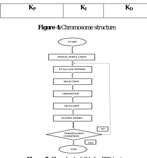
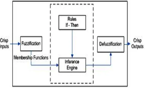
above-normal wellness increment exponentially in progressive eras [9].In this paper, GA is utilized to decide the ideal estimations of the PID controller parameters that fulfil the required element execution qualities of the DC motor drive system. Fig. 3 demonstrates the steps of procedure GA based tuning of PID controller parameters. In the primary, GA is introduced. At that point, it makes a starting populace of PID controller parameters. The populace is created haphazardly, covering the whole scope of conceivable arrangements. The populace is made out of chromosomes. Every chromosome is a competitor answer for the issue. Fig.4 demonstrates the chromosome structure, in which the three parameters (Kp, Ki and Kd) are incorporated. The chromosomes are connected in the DC motor drive system and the dynamic execution attributes of the system are resolved for every chromosome. At that point, the wellness esteem for every chromosome is assessed utilizing the goal capacity. In light of the wellness estimations of the original, a gathering of best chromosomes is chosen to make the following populace. After choice, hybrid and change are connected to this surviving populace so as to enhance the following generation [13]. The procedure proceeds until the end standard is accomplished or the quantity of eras is come to its greatest worth. Hereditary calculation is likewise talked about in part 3 the stream graph of GA is appeared in figure (5). Creating the beginning populace is the initial step of GAs. The populace is made out of the chromosomes that are parallel piece string. The relating assessment of a populace is known as the (wellness work) the wellness quality is greater and the execution is better
Figure 4:Chromosome structure.
Figure 5: Flowchart of GA for PID tuning
V. FUNDAMENTALOFFUZZYLOGICCONTROLLER
Fuzzy logic provides an approximate effective mean of describing the behaviour of some complex system. Unlike traditional logic type, Fuzzy logic aspire to model the vague modes of human reasoning and decision making, which are essential to our ability to make rational decisions in situations of uncertainty and imprecision [14]. Fuzzy logic can be employed to evaluate output variable when an exact mathematical relation of the output variable with input variable not be formulated. Fuzzy logic deal with linguistic variable. The input variable is characterized by membership
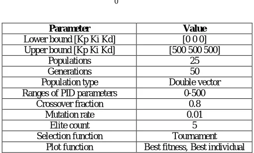
function. A Fuzzy system is represented by input linguistic variables, output linguistic variables along with definitions of linguistic terms and Fuzzy IF-THEN rule base. Basic block diagram of Fuzzy logic controller is shown in the figure.
Figure 6: Configuration of Fuzzy Logic Controller
The Fuzzy Logic controller consists of four fundamental components: fuzzification, a inference engine, knowledge base, and a defuzzification. Each section affects the success of the fuzzy controller and the behaviour of the controlled system [16].In this paper fuzzy logic controller takes two input error and change in error and one output to the DC motor Where:
Change in error (CE) = Error – Previous Error
There are two basic approaches in fuzzy logic controller implementation Sugeno and Mamdani . In this paper Mamdani approach has been used [17].
The Fuzzy inference algorithm implement using Fuzzy IF-THEN rules in a large domain of practical problems such as control, classification, pattern recognition, diagnostics, modeling, and general decision making. There are three principal elements to a Fuzzy logic controller
Fuzzification module (Fuzzifier) Rule base and Inference engine Defuzzification module (Defuzzifier)
VI.TUNINGMETHODOLOGY
Conventional PIDcontroller Tuning Method
Keeping in mind the end goal to decide the parameters of the routine PID controller utilizing delicate figuring tuning as a part of a MATLAB is created. The stride reaction of the uncontrolled DC motor is appeared in Figure 6. It is clear that the uncontrolled DC motor has a reasonable step reaction since the settling time is very poor and not proper working condition second of the reference speed. Then applying PID controller whose speed may be investigated using The Proportional, Integral, Derivative (KP, KI, and KD) gain of the PID controller. Since, classical controllers PID are
Figure 7: Step input of uncontrolled DC motor drive system GA-based optimization
The fitness function is the key to use the GA [14]. The most essential stride in applying GA tuning strategy is to pick the target work that is utilized to assess the fitness value of every chromosome. In this paper, an objective functions are utilized and their execution is looked at. The first depends on integral of the absolute error (IAE) indexand these papers in objective function additionally plan through the MATLAB coding. The parameters of GAs in this study are set as in Table IV. The GA advancement process based IAE index Fig. 6. For every case, the PID controller parameters are resolved. The objective function is given as:
0
( )
TIAE
e t dt
(16)
Table 3:Settings of GA parameters values
The planned PID controller with applying genetic algorithm method is specified Fig.10. And also the genetic algorithm gain values for the tuning is given below in table .the output response of the system is shown in Fig and we analyze the system for the previous parameters
Maximum overshoot, MP Settling time,ts
Rise time, tr
Parameter Value
Lower bound [Kp Ki Kd] [0 0 0] Upper bound [Kp Ki Kd] [500 500 500]
Populations 25
Generations 50
Population type Double vector Ranges of PID parameters 0-500
Crossover fraction 0.8 Mutation rate 0.01
Elite count 5
the maximum overshoot , MP of the system is around zero .the settling time is about then we have go for studying the
consequence of fuzzy logic controller for system and compare the PID based genetic algorithm.
Self tuned Fuzzy Logic Controller
This process is perform in MATLAB with a five membership function type of fuzzy inference arrangement used for the input parameters, that is error and change in error is furthermore designed for the output. Control unit of this system is designed A Mamdani-type fuzzy inference system (FIS) approach is used. The design is shown in Figure5.
Figure 8: Mamdani-type fuzzy logic system
Rule Base
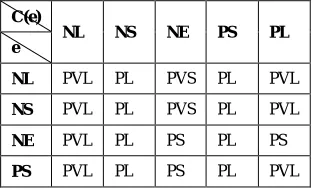
The situate of rules is called a control rule or rule base table. The rules base based on If-Thenset-up and officially the If side is knownas the situation and the Then side is known the finish. The programming is able to perform the rules and split a control signal depending on the precise inputs error(e) and change in error(CE). In a rule based controller the control approach is stored in a more or less natural verbal communication. A rule base controller is easy to know and easy to maintain for a non- specialist and a correspondent controller have been implemented using techniques. The linguistic variables are defined as {NL, NS, ZE, PS, PL}, where NL means negative large, NS means negative small, ZE means zero, PS means positive small and PL means positive large. The fuzzy rules are summarized in Table III. The type of fuzzy inference engine is Mamdani used in this paper. The fuzzy inference system in this study follows as: table III rule base matrix.
C(e)
NL NS NE PS PL e
NL PVL PL PVS PL PVL
NS PVL PL PVS PL PVL
NE PVL PL PS PL PS
PL PL PVL PSP PVL PVL
Table 3:FLC rule base table.
VII. SIMULATIONRESULTSANDDISCUSSION
This paper in objective function a dedicated software using 'C' programming language isdeveloped for this problem in MATLAB. The range of.Kp, Ki and Kd is chosen between (0-500) respectively. Values of Kp, Ki and Kd are plotted through a the objective function in Fig.6. shows the variation of the fitness of the best solution with generation, where best solution is defined as the one which gives minimum rise time, settling time, zero overshoot and nearly zero steady state error in the fitness of the best solution in each generation until it reaches a maximum possible value can be attributed to the novel selection procedure adopted namely combination ofTournament selection with Elitism.
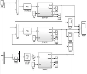
Figure 9: Simulink of dc motor with controller
Figure 11: Step input of controlled DC motor drive system
Tuning method
PARAMETERS Conventional PID Genetic Algorithm IAE Fuzzy Logic Controller
KP 14.7312 5.0196 -
KI 105.15 80.8051 -
KD 0.547 0.0549 -
Rise time(sec) 0.00822 0.745 0.0663
Settling
time(sec) 0.0837 0.12 0.116
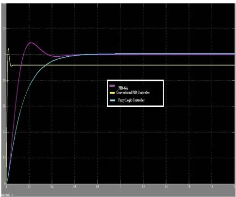
Overshoot (%) 47.40% 0.523 0%
Peak 1.41 0.5 1.02
Table 4: Performance comparison of parameters PID & with GA
VIII. CONCLUSIONS
contrasted with traditional PID controller for the considered system and thus, demonstrated the prevalence of the genetic algorithms. In this finally go to fuzzy best result than other controllers.
REFERENCES
[1] SP. Kumar,SK Veni, YB.Venugopal, YS.K Babu, “A Neuro-Fuzzy based Speed Control of Separately Excited DC Motor”, IEEE Transactions on Computational Intelligence and Communication Networks, pp. 93-98, 2010.
[2] Chung.P, Leo.N, “Transient Performance Based Design Optimization of PM Brushless DC motor Drive Speed Controller”, Proceeding of the IEEE International Conference on Electrical System, Singapore, pp-881-886, June, 2005.
[3] Neenu Thomas, P. Poongodi, “Position Control of DC Motor Using Genetic Algorithm Based PID Controller” Proceeding of the World Congress on Engineering, London, U. K, vol. 2, July 1-3, 2009
[4] V. Antanio, “Research Trends for PID Controllers”, ACTA Polytechnicia Vol. 52, no. 5, 2012.
[5] Jamal A. Mohammed, “ Modeling, Analysis and Speed Control Design Methods of a DC Motor” ,Eng. & Tech.Journal ,vol .29,no.1,2011. [6] C.T. Johnson, R.D. Lorenz,“Experimental identification of friction and its compensation in precise, position controlled mechanism”, IEEE
Trans. Ind ,Applicat, vol.28, no.6, 1992.
[7] A. S. Othman, “Proportional Integral and Derivative Control of Brushless DC Motor,” European Journal of Scientific Research, Vol. 35 No. 2, pp. 198-203, 2009
[8] KH Ang, GCY Chong, Y Li, “PID control system analysis design and technology”, IEEE Transactions on Control Systems Technology ,Vol13, no. 4, pp. 559-576, 2005.
[9] Jamal A. Mohammed, “ Modeling, Analysis and Speed Control Design Methods of a DC Motor” ,Eng. & Tech.Journal ,vol .29,no.1,2011. [10] Santosh Kumar Suman, Vinod Kumar Giri, “Genetic Algorithms: Basic Concepts and Real World Applications”, International Journal of
Electrical, Electronics and Computer Systems (IJEECS), Vol -3, Issue-12, 2015.
[11] PK. Yadav, NL. Prajapati, “An Overview of Genetic Algorithm and Modelling” International Journal of Scientific and Research Publications, vol. 2, September 2012.
[12] R Garg, S Mittal, “Optimization by Genetic Algorithm,” International Journal of Advanced Research in Computer Science and Software Engineering, vol. 4, April 2014.
[13] JH.Halland, “Adaptation in Natural and Artificial system,” The University of Michigan Press, Ann Arbor, MI, 1975.
[14] WR. Hwang, WE. Thompson, “Design of Fuzzy Logic Controllers Using Genetic Algorithms” In Proc. 3rd IEEE Int. Conf. Fuzzy Syst. Orlando, pp. 1383-1388, 1994.
[15] D Liu, Y Jianqiang, T Min. Proposal of GAbased two-stage fuzzy control of overhead crane. Proceedings of IEEE TENCON, IEEE Region 10 Conference on Computers, Communications, Control and Power Engineering, 2000.
[16] O. Cordon, F. Herrera, F. Hoffmann, and L. Magdalena, “Genetic Fuzzy System Evolutionary Tuning and Learning of Fuzzy Knowledge Bases,” World Scientific, 2001.