Transactions of the 17th International Conference on Structural Mechanics in Reactor Technology (SMiRT 17) Prague, Czech Republic, August 17 –22, 2003
Paper # M04-5
Probability Finite Element Assessment Method for Nuclear Graphite
Components
Suyuan Yu, Haiyan Li, Chaoyang Wang, Zhensheng Zhang
Institute of Nuclear Energy Technology, Tsinghua University, Beijing, 100084, China
ABSTRACT
In this paper the probability finite element assessment method is developed to evaluate the security of graphite components in reactors. The MSC.MARC non-linear finite element program is used, and using its user-defined subroutines (UDS) the irradiation thermal analysis subroutine, irradiation static analysis subroutine and probability assessment subroutine are embedded into it. The recompiled MARC program can consider irradiation induced-changes in graphite components such as the coefficient of thermal conductivity, the coefficient of thermal expansion, the creep coefficient, the elastic modulus, and the strength. An axis-symmetrical thick-wall cylinder was used as an example to verify the accuracy and reliability of the program. The failure probability of the graphite components in HTR-10 (10MW High Temperature Gas-cooled Reactor-Test Module) is evaluated. It is shown that the probability finite element assessment method is an effective tool to assess the probability of structure failure.
KEY WORDS: Graphite, Failure Probability, Probability Finite Element Assessment, Irradiation, Creep, MARC.
INTRODUCTION
With the advance of computer technology, the finite element method will provide increasingly accurate analysis for complex structures. But for failure assessment, because most materials present dispersivity property characteristics, such as the tensile strength of graphite[1-3], the deterministic analysis method might meet some difficulty. However the
probabilistic approach is very suitable for analyzing failure assessment problems, and so the probability finite element theory has come into being as a product of structure reliability theory and finite element theory.
The initial idea of probability finite element method is to directly combine the Monte-Carlo simulating method with the finite element results. This kind of method is not applicable to complex structures, because of the tremendous workload. Therefore, a stochastic differential equation has been considered, from which the stochastic finite element model was built. [4-7]
The probability assessment method has also been studied for many years in relation to reactor structure, and some relative rules and criterions have been developed. The ‘KTA 3232’ criterion and JAGURA program of Germany, the VIENUS-STEP program of Japan, and the ADGRA program of China, all adopt the probability assessment theory. With many nuclear power plants gradually approaching their design deadlines, the probability assessment method is being applied more widely. [8]
probability value is within the acceptable range limits, the component should be safe; otherwise it is disabled. This will provide an academic basis for safety monitoring, operating maintenance, safety evaluation and optimization design for HTGRs.
The tensile strength distribution of graphite is considered following the Weibull equation[1,2], whose parameters
can be obtained through experimentation. For graphite IG11, the two parameters are:mt =15.5, and ηt =24.7MPa[3].
PROBABILITY FINITE ELEMENT ANALYSIS PROGRAM[9]
broutines
The probability finite element analysis program of graphite components is based on the MARC non-linear finite element code, which contains many kinds of analysis modules and can do non-linear static analysis, modal analysis, dynamical response analysis, contact analysis, buckling analysis, and failure analysis.
The user can define his own subroutine through the User-Defined Subroutine (UDS) of MARC. The UDS can help the user to complete several functions: 1) define special load conditions, boundary conditions and new state variables (such as neutron field, electromagnetism field); 2) define special material properties and constitutive models (such as anisotropic property, visco-elastic model, visco-plastic model, and plastic model); 3) change the geometry and mesh characteritics of the finite element model; and 4) define new output variables for postprocessing.
The user should add his own code into corresponding subroutines offered by MARC. And the new modified subroutines will be used to form a new executable file for MARC, which can meet the user’s special requirements.
The probability finite element analysis program for graphite components mainly includes three parts: a temperature analysis program (Graphite_Heat), a stress analysis program (Graphite_Stress), and a probability assessment program (Graphite_Probability). Graphite_Heat includes two subroutines, ANKOND and FLUX; Graphite_Stress includes three subroutines, ANEXP, ANELAS, and CRPLAW; and Graphite_Probability includes two subroutines, PLOTV and ELEVAR. The functions of these subroutines are shown in Table 1.
Table 1 Functions of used user-defined su
Name Description
ANKOND Define coefficient of thermal conductivity
FLUX Define heat flux
ANELAS Define elastic modulus changing with the neutron dose ANEXP Define coefficient of thermal expansion CRPLAW Define visco-elastic constitutive model
PLOTV Post-processing subroutine, compute failure probability of the component
ELEVAR Post-processing subroutine, get element quantities (stress, strain, etc.) INTCRD Get coordinates of Gauss Integral Points
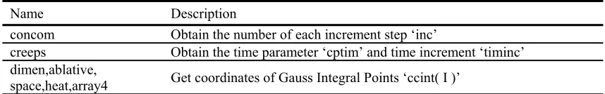
In addition, some common blocks are also used to obtain, store and overwrite some necessary operating parameters. The common blocks used here are shown in Table 2.
Table 2 Common blocks used Name Description
concom Obtain the number of each increment step ‘inc’
creeps Obtain the time parameter ‘cptim’ and time increment ‘timinc’ dimen,ablative,
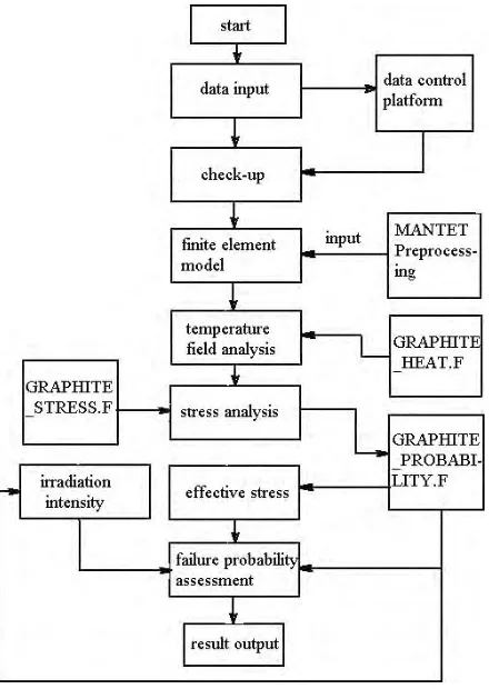
Figure 1 shows the flow chart of the whole program.
Program flow chart Figure 1
VERIFICATION OF THE PROGRAM
To verify the accuracy and reliability of the program, an axis-symmetrical thick-wall cylinder was used as an example[10]. The inner diameter was 10mm, the outer diameter was 50mm, the inner surface temperature was 700
•, and
the outer surface temperature was 650•.
The finite element model used for irradiation effect analysis is shown in Figure 2. The element type was a 4-point plane element. Graphite_Heat.F was first used to make a thermal analysis. The calculated temperature distribution of the cylinder along the radial direction is shown in Figure 3, along with the theoretical value. Then Graphite_Stress.F was used to make a stress analysis, comprehensively considering the temperature field, irradiation deformation, and irradiation creep. The calculated stress and the theoretical value are shown in Figure 4. The results show that the subroutines of Graphite_Heat.F and Graphite_Stress.F are reliable.
(a) Radial stress component (b) Tangential stress component Figure4 Stress analysis result
t
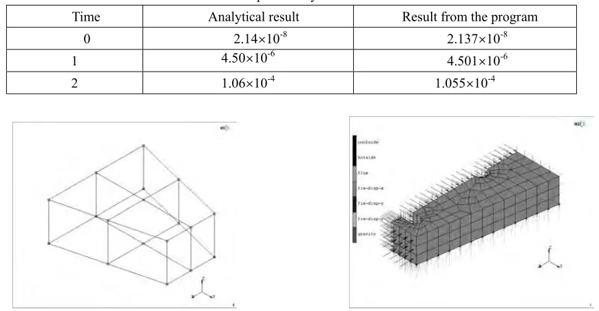
The mesh shown in Figure 5 was used to examine the Graphite_Probability.F subroutine. The result is shown in Table 3. Therefore the Graphite_Probability.F program is also accurate and reliable.
Table 3 Failure probability assessment resul
Time Analytical result Result from the program
0 2.14×10⁻⁸ 2.137×10⁻⁸
1 4.50×10⁻⁶ 4.501×10⁻⁶
2 1.06×10⁻⁴ 1.055×10⁻⁴
HTR-10
ROBABILITY ASSESSMENT OF GRAPHITE REFLECTOR COMPONENTS OF THE HTR-10
Fi
as shown in Figure 6, including a total of 240 elements and 1493 nodes. The element typ
formation heat sources added by user-defined subroutine; and 8) fast Figure 5 FE mesh for probability verification Figure 6 FE model for probability assessment of the
P
nite Element Model and Boundary Conditions
A single fan-shaped graphite brick was used for probability assessment. According to its symmetrical conditions, only 1/4 of the brick was selected,
e was a 20-node 3D element.
All loads and boundary conditions included: 1) self-gravity, -z direction; 2) a heat exchange boundary condition on the helium gas hole (environment temperature: 250•, convection heat exchange coefficient: 0.05W/cm2.•); 3) a heat
exchange boundary condition between the brick and the core (environment temperature: 568.2•, convection heat
exchange coefficient: 0.05W/cm2.
•); 4) y-displacement of x-z plane at zero; 5) z-displacement of x-y plane at zero; 6)
neutron flux added by user-defined subroutine. Mate
h item under a certain mperature and in a certain neutron dose range was acquired by the auto-interpolation method.
An
re only the influence of ence of stress to temperature was ignored.
s
culated using the pr
ability curve under normal op ing conditions.
rial Characteristics
The physical and mechanical characteristics, such as the thermal conductivity coefficient, the thermal expansion coefficient, the creep coefficient, and the elastic modulus, are all related to temperature and the fast neutron dose. Their relationships can be acquired through material experiments. During computation, the value of eac
te
alysis and Results
In each time step, the thermal analysis was completed first, followed by the stress analysis. He temperature to stress was considered, while the influ
According to the stress analysis results, the effective stress value of each Gaus integral point could be calculated, as well as the irradiation intensity. Then the safety degree of each integral point could be acquired. The failure probability of the graphite brick was finally cal
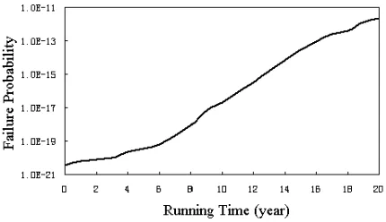
Figure 7 Failure probability curve obability finite element model.
Using this probability assessment program, it was possible to discover the graphite brick’s failure probability curve along operating time. Figure 7 shows the failure prob
erat
Figure 8 Failure probability curve with irradiation Figure 9 Failure probability curve with creep coefficient
deformation increasing 20% decreasing 20%
nfluence of irradiation deformation and creep effect on failure probability, further analysis was
In addition, to see the i
done with the irradiation deformation increasing 20% and the creep coefficient decreasing 20%. The results are shown in Figures 8 and 9.
Figure 7 shows that the failure probability of the graphite brick after normally operating 20 years is 2.268×10⁻¹².
e German criterion ‘KTA 3232’, the HTR-10’s graphite brick has ‘QSKI’ quality grade, its operating cond
ailure probability after operating According to th
ition is ‘BST A’, and its failure probability limit is 10-4. So the HTR-10’s graphite brick can fully satisfy the safety
requirements.
20 years will be 2.041×10⁻¹¹, which is 8.99 times higher than the original value. When the creep coefficient decreases
0%, the result will be 6.304×10⁻¹², which is 2.78 times higher than the original value. CON
t of graphite components under
irrad aphite_Stress.F and
Grap
ite brick of the HTR-10 reactor was completed. The result indicated that
2
CLUSION
The developed program can take into account the material characteristic changes with temperature and neutron flux, and conveniently complete heat exchange analysis, stress analysis and failure assessmen
iation. By changing relative items through the user-defined subroutines of Graphite_Heat.F, Gr hite_Probability.F, it can also be used for other kinds of nonmetal brittle materials.
The reliability and accuracy of the program was verified using a thick-wall graphite cylinder. A failure probability assessment for a graph
the failure probability of the graphite brick after operating 20 years is much less than the limit value of 10-4,
n deformation and the creep characteristic will greatly influence the failure probability of the graphite rick. Either the increase of irradiation deformation or the decrease of the creep coefficient will increase the failure
8(3) 2000, pp.325-334.
4 Application of first order uncertainty analysis in the finite element method in linear elasticity. Proc. according to German criterion ‘KTA 3232’.
Irradiatio b
probability.
REFERENCE
1. M. Ishihara. Statistical Considerations of Graphite Strength for Assessing Design Allowable Stresses. Nuclear Engineering and Design, 19
2. E. Bodmann, Mechanical Design Philosophy for the Graphite Components of the Core Structure of an HTGR. JAERI-M 1987, pp.86-192.
3. Wang Chaoyang, Zhang zhensheng, Yu suyuan. Assessment of Graphite Strength in the HTR-10 Structure (Chinese). Nuclear Power Engineering, 22(4), 2001, pp.321-323.
. Cambou B.
Second Int. Conf. on Applications of Statistics and Probability in Scil. and Struct. Engng. London England. 1971, pp.117-122.
5. Handa K, Anderson K. Application of finite element methods in stastical analysis of structures. Proc. 3rd Int
liability Trondheim, Norway. 1981, pp.409-417.
an, 1985, pp.395-404.
Structural Mechanics (Chinese). Nuclear Power Engineering, 9 ARC2001 User Manual, 2001.
10. Fan Qinshan. Stress Analysis and Strength Design of Pressure Vessels (Chinese). Atomic Energy Publishing Company. China, 1979.
. Conf. on Struct. Safety and Re
6. Yamazaki F, Schnozuka M. Neumann expansion for stochastic finite element analysis, J. Engng. Mech. ASCE, 114, 8, 1988, pp.1335-1354.
7. Der Kiureghian. Finite element based reliability analysis of frame structures. Proc. 4th Int. Conf. On Struct. Safety and Reliability, Kobe, Jap
8. He Shuyan. Several Problems in Application of Reactor 22(4), 2001, pp.289-293.