Design and Analysis of Go-Kart using Finite
Element Method
Karan Bopaiah B.E. Student
Department of Mechanical Engineering Vidya Vardhaka College of Engineering, Mysore, India
Abstract
There are many motor sports in the world. Bikes, Cars are examples of them. But there are also motor sports which do not need professional drivers and need no great speed. This paper explains the designing and fabricating a sound kart having high fuel economy and maximum driver comfort compactness. To achieve the objectives, the rulebook of NKRC 2017 is followed. Design Validation is done by conducting theoretical calculations, simulations and known facts. Analysis are conducted on all major components. The design has been modelled in SOLIDWORKS 2016, the analysis was done in ANSYS 16.0.
Keywords: Go-Kart, Design, Finite Element Analysis, Safe, Optimization
________________________________________________________________________________________________________
I. INTRODUCTION
Go-kart is a simple four-wheeled, small engine, single seated racing car. It is a four wheeled open car. These are mainly used for recreational purposes and sometimes for racing. These karts are powered by four stroke engines, two stroke engines or electric motors. Most of them are single seated but some recreational models can accommodate a passenger. Professional racing karts normally weigh 70-75kg.They can be used in outdoor track and indoor tracks. Outdoor track karts are low speed karts, used strictly for amusement purposes and a faster, powerful kart for racing which are normally equipped with a 4 stroke engine up to 15 HP. Indoor track karts will have a 4 stroke engine with a low power of about 4 to 13 HP. We did our design consideration by the approach of looking into all the alternatives for a system & modelling them in a CAD software like SODIWORKS and analysing it in ANSYS FEA software. Based on the result given by the analysis software, remodelling and retesting of the design was done and the final design was selected. The design process of the vehicle is iterative and is based on various engineering and reverse engineering processes depending upon the availability, cost and other such factors. The entire kart is designed by keeping in mind that it should be able to withstand the racing conditions without failure. Combining this design methodology with the standard engineering design process enabled us to achieve a perfect match of aesthetics, performance, and ease of operation.
II. OBJECTIVE
The main aim to design a Go-kart using suitable material having better performance than that of standard Go-karts but at lower cost with the results obtained from the FEA analysis.
III. METHODOLOGY
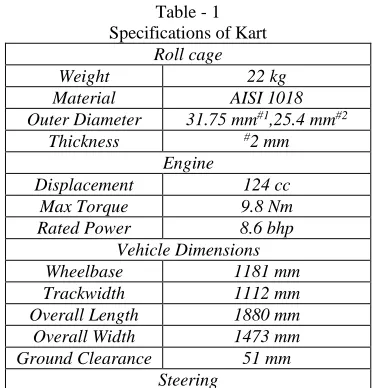
Table - 1 Specifications of Kart
Roll cage
Weight 22 kg
Material AISI 1018
Outer Diameter 31.75 mm#1,25.4 mm#2
Thickness #2 mm
Engine
Displacement 124 cc
Max Torque 9.8 Nm
Rated Power 8.6 bhp
Vehicle Dimensions
Wheelbase 1181 mm
Trackwidth 1112 mm
Overall Length 1880 mm
Overall Width 1473 mm
Ground Clearance 51 mm
Type Pivot Pin Steering System
Turning Radius 2.29 m
Braking
Type Rear Hydraulic
Disc diameter 200 mm
Performance Target
Max. Speed 70 Kmph
Max. Acceleration 3.5 m/s2 Max. Deceleration 30 m/s2
Overall weight 100 kg
Roll Cage Design
The primary function of roll cage is to protect the driver, give a rigid support for the assembly of sub systems, engine and drive train. The roll cage is designed to meet the technical requirements of competition. The objective of the chassis is to encapsulate all components of the kart, including a driver, efficiently and safely. Proper numbers of members are used in the roll cage to ensure complete driver safety. These include the rear roll hoop, the front and rear bumpers, the side bumper, fire extinguisher, battery cover and firewall as per the specifications in the rule book. The bumpers are so designed that they will serve as protection from front and rear and will also add impressive look to the kart. All the bends are of constant radius. In this design, use variable thickness pipes in order to reduce the weight of chassis. For primary and secondary members, 2 mm thick pipes are used respectively.
Table - 2 Design Parameters
Wheelbase 1181 mm
Front Track Width 1112 mm
Rear Track Width 1371mm
Height 813 mm
Outer Diameter 31.75 mm#1,25.4 mm#2
Thickness #2 mm
No. of welds 41
Pipe Length 22500 mm
Material
The selection of material for chassis is done by detailed study of properties of material regarding strength and cost, results found that three materials AISI 1018, AISI 1020 and AISI 4130. We prefer to use AISI 1018 over AISI 1020, because of its higher yield strength and high strength to weight ratio and over AISI 4130 because of relatively lower cost.
The material AISI-1018 is used in the chassis design because of its good weld ability, relatively soft and strengthens as well as good manufacturability. A good strength material is important in a roll cage because the roll cage needs to absorb as much energy as possible to prevent the roll cage material from fracturing at the time of high impact. AISI- 1018 has chosen for the chassis because it has structural properties that provide a high strength to weight ratio.
Table - 3 Properties of Material Ultimate Strength 420 MPa
Yield Strength 310 MPa
Density 7870 kg/m3
Strength to Weight Ratio 60 KN-m/kg
Elongation 15%
The Chemical Composition of Material is: Carbon C = 0.18 %
Manganese Mn = 0.73 % Silicon Si = 0.18 % Sulphur S = 0.017 % Phosphorus P = 0.020 % Iron Fe = 98.81 %
Welding
The material which is used AISI-1018 has good weld ability. All welds on the vehicle are made using a Electric Arc welding process. Arc welding is the process of joining metal – steel in this case – using electricity. Rather than most other formats, which generally use gas, this process uses electricity to create enough heat to melt the metal and fuse it together during cooling. Works on dirty metal. Processes can be completed during wind or rain, and spatter isn’t a major concern.
IV. ANALYSIS
Structural integrity of the frame is verified by comparing the analysis result with the standard values of the material. Analysis was conducted by use of finite element analysis FEA on ANSYS software. To conduct finite element analysis of the chassis an existing design of chassis was uploaded from the computer stresses were calculated by simulating three different induced load cases. The load cases simulated were frontal impact, side impact, and rear impact. The test results showed that the deflection was within the permitted limit.
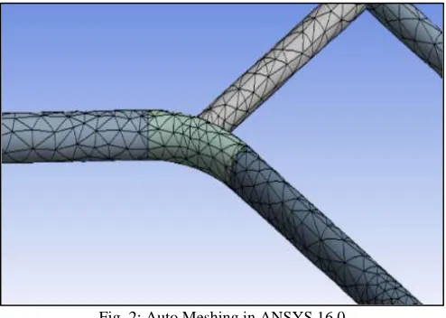
Meshing
Auto meshing has been done in ANSYS 16.0 software. Following data has been found after meshing of chassis – No. of Nodes = 125008
No. of Elements = 65288
Fig. 2: Auto Meshing in ANSYS 16.0 Rear Impact
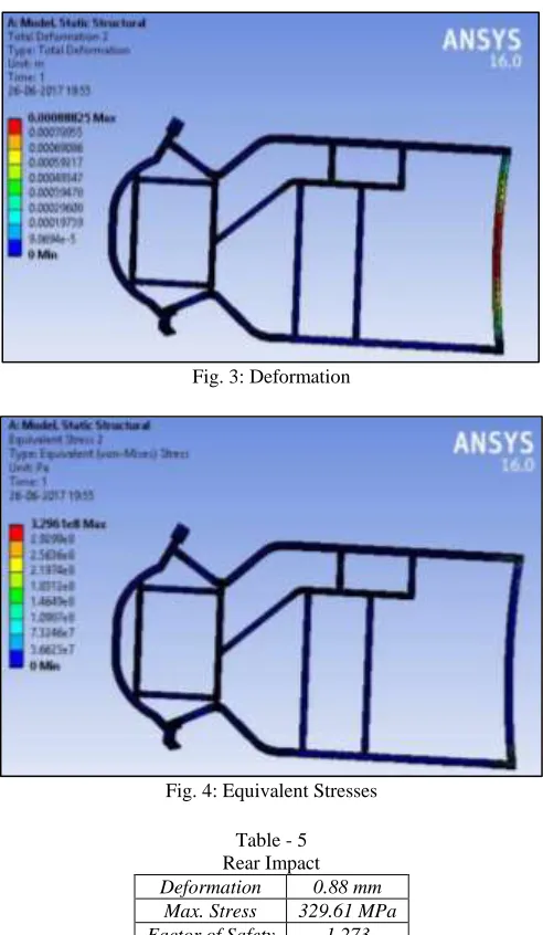
Considering the worst case collision for rear impact, force is calculated as similar to front impact for speed of 60 kmph. The value of 5g force has been calculated. Load was applied at rear end of the chassis while constraining front end and king pin mounting points. Time of impact considered is 0.2 seconds as per industrial standards.
Fig. 3: Deformation
Fig. 4: Equivalent Stresses Table - 5 Rear Impact Deformation 0.88 mm
Max. Stress 329.61 MPa Factor of Safety 1.273
Front Impact
For the front impact, engine and driver load was given at respective points. The kingpin mounting points and rear wheels position kept fixed. Front impact was calculated for an optimum speed of 60 kmph. From impulse momentum equation, 5g force has been calculated. The loads were applied only at front end of the chassis because application of forces at one end, while constraining the other, results in a more conservative approach of analysis. Time of impact considered is 0.2 seconds as per industrial standards. F x t = m x (Vi - Vf)
F x 0.2 = 160 x (16.38 - 0) F=13.1 KN
Fig. 6: Equivalent stresses Table - 4 Frontal Impact Deformation 0.6 mm
Max. Stress 255.3 MPa Factor of Safety 1.645
Side Impact
The most probable condition of an impact from the side would be with the vehicle already in motion. So it was assumed that neither the vehicle would be a fixed object. For the side impact the velocity of vehicle is taken 30 kmph and time of impact considered is 0.2 seconds as per industrial standards. Impact force was applied by constraining left side of chassis and applying load equivalent to 2.5g force on the right side.
F x t = m x (Vi-Vf) F x 0.2 = 160 x (8.19 -0) F=6.5 KN
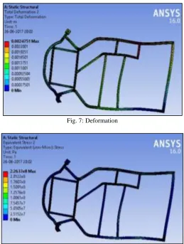
Fig. 7: Deformation
Table – 6 Side Impact Deformation 2.47 mm
Max. Stress 226.3 MPa Factor of Safety 1.855
Modal Analysis
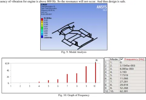
Modal analysis was carried out for chassis and frequency of vibration was found to be less than desired engine frequency. The maximum frequency of chassis vibration is nearly 100 Hz and the results of analysis have been shown below. The minimum frequency of vibration for engine is above 800 Hz. So the resonance will not occur. And thus design is safe.
Fig. 9: Modal Analysis
Fig. 10: Graph of Frequency V. CONCLUSION
Result concluded that the AISI 1018 material is more economic and gives better performance. It is also suitable for large scale production. Static analysis using finite element method was successfully carried out on chassis CAD model to determine equivalent stresses, maximum deformations, Factor of Safety and its location on chassis model. The Factor of safety calculated is found to be greater than 1. Hence the chassis design is safe. This paper gives adequate idea and design guidelines about modelling of Go-Kart. Thus after all the analysis and design calculation, It concluded that our design of Go-kart is safe for fabrication using healthy manufacturing practices.
REFERENCES
[1] Shigley, Joseph Edward, Theory of Machines and Mechanisms, Tata Mcgraw Hill, New York, 2003.
[2] Khurmi, R.S. And Gupta, J.K., A Textbook Of Theory Of Machine, 4th Edition, Eurasia Publishing House (Pvt.), Ltd, New Delhi, 2003.
[3] AritraNath, C.JagadeeshVikram, “Design and Fabrication of a GoKart ”International Journal of Innovative Research in Science, Engineering and Technology, Vol. 4, Issue 9, September 2015, ISSN No.: 2319-8753.
[4] Dr. D. Ravikanth , C. Nagaraja, “Fabrication of a Model Go-Kart (With Low Cost)” Journal of Mechanical and Civil Engineering (IOSR-JMCE) e-ISSN: 2278-1684,p-ISSN: 2320-334X, Volume 12, Issue 6 Ver. V (Nov. - Dec. 2015), PP 24-30
[5] N. R. Patil, Ravichandra R. Kulkarni, “Static analysis of Go-Kart Chassis frame by Analytical and SolidWorksSimulation”, International Journal of Scientific Engineering and Technology, Volume No.3 Issue No.5, 1 May 2014, pp : 661-663, (ISSN : 2277-1581).
[6] Mr. GirishMekalke, “Static Analysis of a Go-kart Chassis”, International Journal of Mechanical and Industrial Technology,Vol. 3, Issue 2, pp: (73-78), Month: October 2015 - March 2016,ISSN 2348-7593 (Online).
[7] Rahul Thavai, Quazi Shahezad, Mirza Shahrukh, “Static Analysis of GoKart Chassis by Analytical and Solid Works Simulation”, International Open Access Journal of Modern Engineering Research (IJMER) Vol. 5, Iss.4, Apr. 2015.