ISSN (Print) : 2320 – 3765 ISSN (Online): 2278 – 8875
I
nternational
J
ournal of
A
dvanced
R
esearch in
E
lectrical,
E
lectronics and
I
nstrumentation
E
ngineering
(An ISO 3297: 2007 Certified Organization) Vol. 4, Issue 4, April 2015
A Comparative Analysis of Direct Torque
Control and Direct Torque Control using Space
Vector Modulation for Torque Ripple
Reduction
Sunita Kumari Jain
1, Fanibhushan Sharma
2M. Tech Student, Dept. of EEE, Govt. Women Engineering College, Ajmer, India1 Assistant Professor, Dept. of EEE, Govt. Women Engineering College, Ajmer, India2
ABSTRACT: There are many control techniques of induction motor. One of them is direct torque control (DTC) scheme.
The basic concept of direct torque control of induction motor is to control the flux and electromagnetic torque. The direct torque control scheme is used to obtain the good dynamic control and high performance of the motor. In the proposed paper, firstly the conventional direct torque control scheme of induction motor has been studied. In this scheme, the hysteresis comparators are used to compensate the flux and torque errors. Due to these comparators, conventional DTC suffers from high torque ripples and also switching frequency is variable. Thus, to reduce the torque ripples and to maintain the switching frequency constant, space vector modulation (SVM) scheme is used with direct torque control. The simulation result in MATLAB/SIMULINK shows the superiority of DTC-SVM.
KEYWORDS: Induction Motor model, Conventional Direct Torque Control, Space Vector Modulation.
I. INTRODUCTION
These days, induction motors are extensively used in industrial, commercial and domestic applications. Three-phase induction motor is also called asynchronous speed machine because when motoring action performed, these operates below synchronous speed and when generating action performed, they operates above synchronous speed. These motors are less expensive as compared to synchronous as well as DC motors. But in the induction motors, the speed is not controlled as easily as controlled with DC motor.
There are many control techniques of induction motor. One of them is direct torque control strategy. Direct torque control strategy was initially described by German and Japanese researchers Takahashi and Noguchi. Direct torque control (DTC) drives are finding great interest, since ABB recently introduced the first industrial direct-torque-controlled induction motor drive in the mid-1980„s, which can work even at zero speed. This is a very significant industrial contribution.
ISSN (Print) : 2320 – 3765 ISSN (Online): 2278 – 8875
I
nternational
J
ournal of
A
dvanced
R
esearch in
E
lectrical,
E
lectronics and
I
nstrumentation
E
ngineering
(An ISO 3297: 2007 Certified Organization) Vol. 4, Issue 4, April 2015
II. RELATED WORK
Chee-mun Ong [1] describe the techniques of modeling and simulation of electrical machinery. This shows the circuit model of 3-phase induction machine with all its reference frames. Transient and steady state model for induction machine is also explained. Rashid M. H. [2] presented the vector control system. Later he gives an instantaneous torque control with DTC which gives very fast torque response. Vaibhav B. Magdum clarified the basic concept behind direct torque control. He also explains the field orientation control and direct-self control in adaptive motor model block. Information on the ancillary control blocks outside the basic DTC is also given [3]. A direct torque control scheme of machine is given by Jun Koo Kang, which minimize the torque ripples and maintain the switching frequency constant. In the proposed strategy, by using instantaneous torque equation, an rms torque-ripple equation is derived. An optimal switching instant is determined at each switching cycle, which satisfies the minimum torque-ripple condition [4].
Jose Rodriguez gives a new method of DTC which is based on load angle control. To obtain the control algorithm, simple equations are used. This makes it easy for implement and understands. By using SVM, low torque ripples are obtained and switching frequency is maintained constant. This SVM strategy overcomes the drawbacks of classical DTC [5]. Zhifeng Zhang explains a DTC-SVM scheme in favor of an adjustable speed sensor-less induction motor drive which is supplied by a 2-level SVPWM inverter. By using an input-output feedback linearization control, the inverter reference voltage is obtained. Also a full-order adaptive stator flux observer is designed and a new speed adaptive law is given. Thus the stability of the observer system is ensured [6]. S. A. Zaid [7] suggested a decoupled control of amplitude and stator flux angle to generate the pulses of voltage source inverter. MATLAB/SIMULINK software simulates the suggested and conventional DTC. The use of SVM enables fast speed and torque responses. Variations of motor parameter do not affect the optimization in the new method. M. satheesh Kumar presents the comparative evaluation of the two popular control strategies for induction motor drive. These strategies are classical DTC and DTC-SVM. The Simulink model of both classical and SVPWM direct torque control drives are simulated in all the four quadrant of operation) and the results are analyzed [8].
ALNASIR Z. A. presents the design of a direct torque control model and tested using MATLAB/SIMULINK package. Simulation results illustrate the validity & high accuracy of the proposed model [9]. A new torque ripple reduction scheme is proposed with a modified look up table. This table including a large no. of synthesized non-zero active voltage vector to overcome the limitation of the conventional strategy and duty ratio control switching strategy [10]. The DTC principle is based upon the decoupling of torque and stator flux. Direct torque control method employees hysteresis comparator which produces high ripples in torque and switching frequency is variable. The proposed DTC-SVM scheme reduces torque ripples and preserves the DTC transient merits. The SVM technique is utilized to obtain the required voltage space vector which compensates the flux and torque errors, at each cycle period [11] [12].
In the given traditional SVPWM algorithm, the evaluation of sectors is done with the complex operation of coordinate rotation, trigonometric & inverse trigonometric function and so on. Due to the complexity to realize this algorithm, a simplified SVPWM algorithm is introduced to build the model of DTC drive system [13]. A hybrid control direct torque control (DTC) scheme is given for medium voltage induction motor drive. For the closed loop implementation of the recommended scheme, an application of carrier-based space vector modulation (CBSVM) controlled five-level diode-clamped multi-level inverter (DCMLI) is presented [14].
III. INDUCTION MOTOR MODEL
ISSN (Print) : 2320 – 3765 ISSN (Online): 2278 – 8875
I
nternational
J
ournal of
A
dvanced
R
esearch in
E
lectrical,
E
lectronics and
I
nstrumentation
E
ngineering
(An ISO 3297: 2007 Certified Organization) Vol. 4, Issue 4, April 2015
the steady state variables are constant and do not vary sinusoidally with time. In this paper, induction machine model is described in the stationary reference frame.
IV. CONVENTIONAL DIRECT TORQUE CONTROL (DTC) STRATEGY
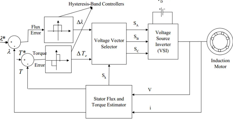
The principle of conventional DTC is shown in fig 1. The reference and actual values of flux and torque is compared and then proceed to the hysteresis band controller. The stator flux and torque estimator calculates the flux and torque from the induction motor terminal voltages and currents. For that, the 3-phase quantities are converted into two phase stationary d-q components. Then, they are used for estimating motor torque and stator linking flux. A three-dimensional look up table is referred to decide the inverter switching states. This table is based on the resultant flux position and the errors in flux magnitude and in torque. The stator flux and torque estimator block gives the sector no. Sk , in which the flux vector lies, to
the voltage vector selection block.
Fig. 1 Conventional DTC Configuration
A. Estimation of Electromagnetic Torque and Stator Flux Linkage The stator flux-linkage space vector is given by the equation:
( )
s Vsq R is sq dt
(1) Where,s sd jsq, Vs Vsd jVsqand is isd jisq( )
sd Vsd R is sd dt
(2)( )
sq Vsq R is sq dt
(3)Where, λsd, isd, Vsd and λsq, isq, Vsq, are the d-axis and q-axis quantities of stator flux linkage space vector, stator current
space vector, and stator voltage space vector component respectively. The electromagnetic torque is given by:
3
( )
2
e sd sq sq sd
ISSN (Print) : 2320 – 3765 ISSN (Online): 2278 – 8875
I
nternational
J
ournal of
A
dvanced
R
esearch in
E
lectrical,
E
lectronics and
I
nstrumentation
E
ngineering
(An ISO 3297: 2007 Certified Organization) Vol. 4, Issue 4, April 2015
B. Torque and Flux Controller
In Figure 1, the reference value and actual value of the stator flux linkage space vector is compared and the error is fed into the 2-level stator flux hysteresis comparator. In a similar way, the reference value and actual value of the electromagnetic torque is compared and the error is fed into the 3-level torque hysteresis comparator.
The digital output signal of a flux hysteresis comparator (2-level) is:
1
if *(
)
s s s
, Stator flux to be increased.0
if *( )
s s s
, Stator flux to be decreased.
The digital output signals of a torque hysteresis comparator (3-level) are given below: 1
e
dT if *
( )
e e e
T T T , Torque to be increased.
0 e
dT if *
e e
T T , No change in torque is required.
1
e
dT if Te (Te* Te), Torque to be increased.
C. Look-up Table
The output of the hysteresis controllers are given to the look-up table where the required voltage vector is selected for the inverter.This voltage space vector is determined based on the position of the stator flux and required changes in torque and flux magnitude. Then, the selected voltage vector is applied to the induction motor.
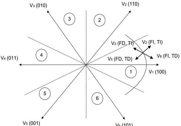
Fig. 2 Stator Flux Vector Locus and Different Possible Switching Voltage Vectors
The stator voltage strikes directly the stator flux in accordance with the equation:
s s s s
d
V or V t
dt
(5)
In VSI, there are eight possible switching vectors in which six are active vectors and two zero vectors. The flux can be increased by V1, V2 and V6 vectors and decreased by V3, V4 and V5 vectors. Similarly, the torque can be increased by V2, V3
ISSN (Print) : 2320 – 3765 ISSN (Online): 2278 – 8875
I
nternational
J
ournal of
A
dvanced
R
esearch in
E
lectrical,
E
lectronics and
I
nstrumentation
E
ngineering
(An ISO 3297: 2007 Certified Organization) Vol. 4, Issue 4, April 2015
TABLE 1
Switching Vector Selection Table
T S1 S2 S3 S4 S5 S6FI TI V2 V3 V4 V5 V6 V1
TE V0 V7 V0 V7 V0 V7
TD V6 V1 V2 V3 V4 V5
FD TI V3 V4 V5 V6 V1 V2
TE V7 V0 V7 V0 V7 V0
TD V5 V6 V1 V2 V3 V4
V. DIRECT TORQUE CONTROL USING SPACE VECTOR MODULATION
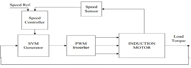
The main disadvantages of conventional DTC are high torque ripples and also the switching frequency is variable. Several techniques have been developed to overcome the disadvantages of conventional DTC. One of them is direct torque control using Space vector modulation (SVM). Space vector modulation is an algorithm which is used to calculate the required voltage space vector to compensate the flux and torque errors. The operating principle of DTC-SVM is shown in below fig. First of all, the actual speed is compared with the reference speed for the closed loop speed control. In the speed controller, two PI controllers are used which gives the reference voltage and frequency to generate the three phase sinusoidal signals. These signals are used in SVM generator and based on the space vector position in space SVM calculates proper switching time for two consecutive switching vectors and also for zero switching vector. Based on that vector, inverter gives supply to the induction machine.
Fig. 3 Operating Principle of DTC-SVM
A. SVM with 2-Level Inverter
To implement space vector modulation, a reference voltage vector signal V* is sampled with a sampling time Ts. To synthesize the reference vector, a combination of two adjacent active switching vectors and one or both of the zero vectors are required. According to SVM switching rule, Vs should be a circle i.e. only one switching per state transition. In this rule,
ISSN (Print) : 2320 – 3765 ISSN (Online): 2278 – 8875
I
nternational
J
ournal of
A
dvanced
R
esearch in
E
lectrical,
E
lectronics and
I
nstrumentation
E
ngineering
(An ISO 3297: 2007 Certified Organization) Vol. 4, Issue 4, April 2015
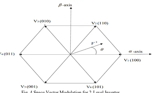
Fig. 4 Space Vector Modulation for 2-Level Inverter
Space vector modulation scheme can be applied by two steps:
Three-phase to Two-phase transformation and determination of Vt and
Dwell time calculation
1. Three-phase to Two-phase transformation and determination of Vt and
In this modulation technique, the three-phase quantities are transformed to two-phase quantities in stationary reference frame. And the reference vector is calculated as:
1 1
( ) 1
2 2 2
( )
3 3 3
( ) 0 2 2 AO BO CO V t V V t V V t
(6) ( ) ( )
t
V V t jV t (7)
* 2 2
V V V
, 1 tan V V
(8) 2. Dwell Time CalculationThe dwell time calculation (duration of each voltage vector) is based on “volt-second” balancing principle, i.e., the product of the sampling period Ts and reference voltage V* equals the sum of the voltage multiplied by the time interval of chosen space vectors.
The “volt-second” balancing equation is given by:
* ' ' '
1 1 2 2 0 0
s
V T V t V t V t (9)
' ' '
1 2 0
s
T t t t (10)
Where,
' 1
t
,t
2' andt
0' = dwell times for the vectors V1, V2, and V0 respectively.If sector 1 is selected, the space vectors in equation (9) can be expressed as:
ISSN (Print) : 2320 – 3765 ISSN (Online): 2278 – 8875
I
nternational
J
ournal of
A
dvanced
R
esearch in
E
lectrical,
E
lectronics and
I
nstrumentation
E
ngineering
(An ISO 3297: 2007 Certified Organization) Vol. 4, Issue 4, April 2015
Fig. 5 Reference Vector (V*) Synthesized by V1, V2,V0
Generally, we write V* can be written as:
V*=V*ej
(12)Substitute Equations (11) and Equation (12) into Equation (9) and then separate the real (α-axis) and imaginary (β-axis) components of the resultant equation in the (α– β) plane, we get:
Real Axis-
* ' '
1 2
(cos )
s2 / 3
D1/ 3
DV
T
V t
V t
(13) Imaginary Axis-* '
2
(sin ) s 1/ 3 D
V
T V t (14) By solving equation (13) and equation (14) with ' ' '1 2 0
s
T t t t gives:
' *
1
3
sin( ) 3 s
D
t T V
V
(15)
' *
2
3
sin( )
s D
t T V
V
for 0
3
(16)
' ' '
0 s 1 2
t
T
t
t
(17)VI. SIMULINK MODEL AND RESULTS
The conventional direct torque control and direct torque control using space vector modulation (DTC-SVM) scheme is simulated in MATLAB/SIMULINK software. The comparison is made and shows the superiority of DTC-SVM.
ISSN (Print) : 2320 – 3765 ISSN (Online): 2278 – 8875
I
nternational
J
ournal of
A
dvanced
R
esearch in
E
lectrical,
E
lectronics and
I
nstrumentation
E
ngineering
(An ISO 3297: 2007 Certified Organization) Vol. 4, Issue 4, April 2015
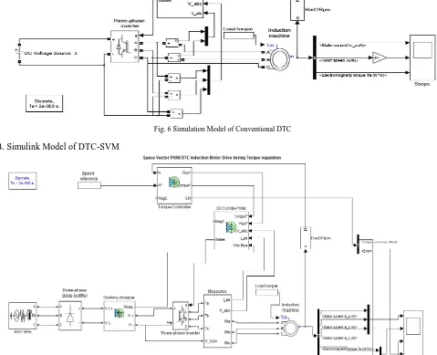
Fig. 6 Simulation Model of Conventional DTC
B. Simulink Model of DTC-SVM
Fig. 7 Simulation Model of DTC-SVM
C. Simulation Results
The control scheme is simulated with MATLAB/SIMULINK, for following case as:
ISSN (Print) : 2320 – 3765 ISSN (Online): 2278 – 8875
I
nternational
J
ournal of
A
dvanced
R
esearch in
E
lectrical,
E
lectronics and
I
nstrumentation
E
ngineering
(An ISO 3297: 2007 Certified Organization) Vol. 4, Issue 4, April 2015
The load torque prescribed to (0; 12) Nm at t = (0; 1.5) s with step variation.
The variations in time of the electrical and mechanical variables are obtained, specific to the presented drive ( stator current isa, the rotor current ira, the rotor speed N and the electromagnetic torque Tem) and it represents them in figure 6 and figure 7.
Time (Sec)
Fig. 8 Time vs. Stator Current in DTC
In fig.8, it shows the graph of time vs. stator current. From the above graph we can say that with conventional direct torque control, the current is pulsating largely when compared to fig. 11 in DTC-SVM.
Time (Sec)
Fig. 9 Time vs. Rotor Speed in DTC
In fig.9, it shows the graph of time vs. rotor speed. At t = (0; 1.5) sec, the speed reference prescribed to (800; 1000) rpm.
Time (Sec)
ISSN (Print) : 2320 – 3765 ISSN (Online): 2278 – 8875
I
nternational
J
ournal of
A
dvanced
R
esearch in
E
lectrical,
E
lectronics and
I
nstrumentation
E
ngineering
(An ISO 3297: 2007 Certified Organization) Vol. 4, Issue 4, April 2015
Time (Sec)
Fig. 11 Time vs. Stator Current in DTC-SVM
In the fig.11, it shows the graph plotted between three phases of stator current and time. From the above fig, we can say that current pulsations are less in DTC-SVM as compared to conventional DTC.
Time (Sec)
Fig. 12 Time vs. Rotor Speed in DTC-SVM
In fig.12, it shows the plot between rotor speed vs. time. At t = (0; 1.5) sec, the speed reference also prescribed to (800; 1000) rpm.
Time (Sec)
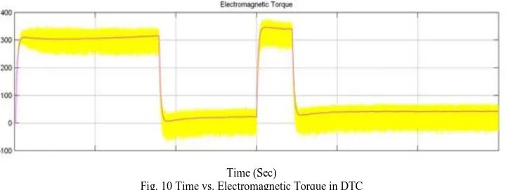
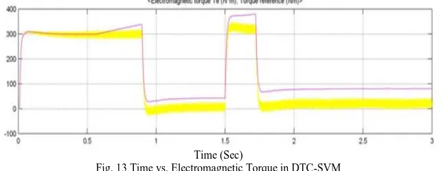
Fig. 13 Time vs. Electromagnetic Torque in DTC-SVM
In the fig.13, it shows the graph between time and electromagnetic torque. It shows that in DTC-SVM, the torque ripples are much less about (±1.5) Nm, as compared to conventional DTC.
VII. CONCLUSION
ISSN (Print) : 2320 – 3765 ISSN (Online): 2278 – 8875
I
nternational
J
ournal of
A
dvanced
R
esearch in
E
lectrical,
E
lectronics and
I
nstrumentation
E
ngineering
(An ISO 3297: 2007 Certified Organization) Vol. 4, Issue 4, April 2015
implemented with voltage modulator. Steady State torque ripple is considerably reduced in DTC-SVM. From simulation results, the torque ripples in DTC-SVM is (±1.5) Nm, which is much less as compared to conventional DTC (±5) Nm. Also the switching frequency is maintained constant.
REFERENCES
[1] Chee Mun Ong, “Dynamic Simulation of Electric Machinery, Using Matlab/Simulink”, ISBN 0-13-723785-5, Prentice Hall PTR, 1998. [2] Rashid M.H., “Power Electronics Circuits, Devices and Applications”, Pearson Education, third Edition, 2004.
[3] Vaibhav B. Magdum, Ravindra M. Malkar and Darshan N. Karnawat, “Study and Simulation of Direct Torque Control Method for Three Phase Induction Motor Drives”, International Journal of Electrical Engineering and Technology, Vol. 2, No.1, pp. 1-13, 2011.
[4] Jun Koo Kang, Seung-Ki Sul, “New Direct Torque Control of Induction Motor for Minimum Torque Ripple and Constant Switching Frequency”, IEEE Transaction on Industry Applications, Vol. 35, No.5, pp. 1076-1082, 1999.
[5] Jose Rodriguez, Jorge Pontt, Caser Silva, Samir Kouro, and Hernan Miranda, “A Novel Direct Torque Control Scheme for Induction Machines With Space Vector Modulation”, 35th Annual IEEE Power Electronics Specialists Conference, Vol. 2, pp. 1392-1397, 2004.
[6] Zhifeng Zhang, Renyuan Tang, Baodong Bai, and Dexin Xie, “Novel Direct Torque control Based on Space Vector Modulation With Adaptive Stator Flux Observer for Induction Motors”, IEEE Transactions on Magnetics, Vol. 46, No.8, pp. 3133-3136, 2010.
[7] S. A. Zaid, O. A. Mahgoub, And K. A. EL-Metwally, “Implementation of a New Fast Direct Torque Control Algorithm for Induction Motor Drives”, IET Electr. Power Applications, Vol. 4, No.5, pp. 305-313, 2010.
[8] M. Satheesh Kumar, P. Ramesh Babu, and S. Ramprasath, “Four Quadrant Operation of Direct Torque Control-SVPWM Based Three Phase Induction Motor Drive in MATLAB/SIMULINK Environment”, IEEE International Conference on Advanced Communication Control and Computing Technologies, pp. 397-402, 2012. [9] Alnasir, Z. A., Almarhoon A. H., “Design of Direct Torque Controller of Induction Motor (DTC)”, International Journal of Engineering and Technology, Vol. 4, No.2, pp.
54-70, 2012.
[10] Bhoopendra Singh, Shailendra Jain, and Sanjeet Dwivedi, “Torque Ripple Reduction Technique with Improved Flux Response for a Direct Torque Control Induction Motor Drive”, IET Power Electronics, Vol. 6, N0.2, pp. 326-342, 2013.
[11] Mustafa A. Al-Refai. “Matlab/Simulink Simulation Model for Direct Torque Control Based On Space Vector Modulation (DTC-SVM) of Induction Motor Drive”, World Academy of Science, Engineering and Technology 76, pp. 658-662, 2013.
[12] Anjana Manuel, Jebin Francis, “Simulation of Direct Torque Controlled Induction Motor Drive by Using Space Vector Pulse Width Modulation For Torque Ripple Reduction”, International Journal of Advanced Research in Electrical, Electronics and Instrumentation Engineering, Vol. 2, No.9, pp. 4471-4478, 2013.
[13] Wang Dongmei, Liu Lingshun, and Liu Di, “Modeling and Simulation Research of Asynchronous Motor Direct Torque Control System Based on the Simplified SVPWM”, The Tenth International Conference on Electronic Measurement and Instruments, pp. 308-311, 2011.
[14] UdayKumar V Patil, Hiralal Murlidhar Suryawanshi, and Mohan M. Renge, “Closed-loop Hybrid Direct Torque Control For Medium Voltage Induction Motor Drive For Performance Improvement”, IET Power Electronics, Vol. 7, N0.1, pp. 31-40, 2013.
APPENDIX-I
Parameters used in Induction Motor Model
Power Rating 149.2e3 Hp
Stator Voltage 400 V
Frequency 50 Hz
No. of Poles 4
Stator Resistance 14.85e-3
/phaseStator Leakage Inductance 0.3027e-3 H/phase
Rotor Resistance 9.295e-3
/phaseRotor Leakage Inductance 0.3027e-3 H/phase
Mutual Inductance 10.46e-3 H
Inertia 3.1 kg m2