Comparative Studies on Evolutionary
Computational Techniques for Speed Control
of A DC Motor
M. B. Anandaraju#1, Dr. P.S. Puttaswamy *2
#
HOD, Dept. of ECE, BGSIT, Mandya, India. *
Professor, Dept. of EEE, PESCE, Mandya, India.
ABSTRACT: Proportional-Integral-Derivative (PID) Controllers plays a significant role in many industrial and commercial applications. Designing of PID controller is always a challenging problem especially for high order systems. It is known that PID Controller is employed in every aspect of industrial automation. The PID Controller applications are spanned from small industry to higher technology industries. Hence, the problem is always how to optimize the PID Controller. Generally, initial designs obtained by all means need to be adjusted repeatedly through computer simulations until the closed-loop system performs or compromises as desired. This simulation involves the development of “intelligent” tools that can assist engineers to achieve the best overall PID control for the entire operating range. Self-tuning method for PID Controller using Evolutionary Computational (EC) Techniques capable of providing robust design. In this paper two types of tuning methods are presented, namely Genetic Algorithm and Modified Interactive Evolutionary Computation Method. The results obtained by them based on velocity control of DC motor and harmonic analysis are analysed and a comparative study of the two are presented.
KEYWORDS: DC motor, PID, Genetic Algorithm, MIEC
I.INTRODUCTION
10.15662/ijareeie.2014.0308060
d e kt
i()
dt t de kd
) (
) (t e Kp
Fig.1: Block Diagram of PID Controller
A Tuning:
Once the gains of various control parameters are obtained the next step is all about tuning. Tuning a control loop means the modification of its control parameters to its optimum values for the desired control response. While tuning stability of the system must be taken in to consideration. Tuning plays a very important role in all PID controllers. PID tuning is a difficult problem, even though there are only three parameters and in principle it is simple to describe, but it must satisfy complex criteria within the limitations of PID control. There are accordingly various methods for loop tuning. In all the methods, usually, initial designs need to be adjusted repeatedly through computer simulations until the closed-loop system performs or compromises as desired. There are several conventional methods for tuning the PID controller. Namely, Ziegler-Nichols, Cohen-Coon and Chien-Hrones-Reswick procedures. But the rapid advances in computer technologies have enabled high-performance measurement and control systems to form an essential part of industrial plants which was not possible in conventional tuning methods.
Based on the literature survey carried out it has been felt that there is a sufficient scope to implement newer and more powerful control algorithm for tuning the PID Controller to achieve better performance. In this context EC algorithms such as Genetic Algorithm (GA) and Modified Interactive Evolutionary Computation (MIEC) are chosen for implementation. The present paper deals with the optimization of controller parameter and the velocity control of DC Motor which can provide the better performance due to better optimized values of PID Controller tuning parameters using both GA and MIEC and their results are compared. The simulation studies have been carried out using MATLAB / SIMULINK model to look into the feasibility of the proposed scheme.
II MODELING A DC MOTOR
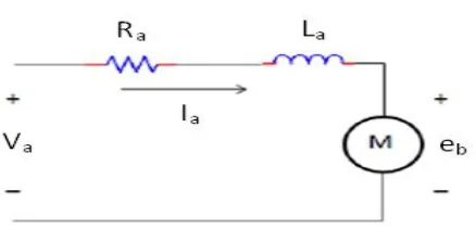
Electric DC Motor converts electrical energy to mechanical energy using the electromagnetic induction principle [9]. Fig. 2 represents the schematic representation of a DC Motor. To achieve velocity control of a DC Motor, the primary requirement is to model the DC Motor system itself [10]. In control systems terminology it is referred to as plant modeling. The major steps in developing a DC Motor model are as follows:
(i)
Represent the system’s schematic of DC Motor.(ii)
Formulate the system equations.(iii)
Generate the transfer function.(iv)
Develop the SIMULINK model.Fig. 2: Schematic Representation of DC Motor
In practice, running a motor at steady speed requires a small amount of current to flow sufficient to just overcome the friction at that speed. The rotor coil will also have some resistance, so any current will cause Ohmic losses and a small voltage drop. The coil also has self inductance if the current in the coil changes then there will be an induced back Electro-Motive Force (EMF) which opposes that change.
A. System Equations:
Considering the above mentioned Fig 4.4, the armature resistance, Inductance and the back EMF of the presented model are Ra, La, eb respectively.The motor torque τ is related to the armature current Ia by torque constant K. The
motor torque τ is the force which is required to provide an angular rotation or a force required to rotate the object about
its axis. The torque force is related to the armature current i , torque constant K represented as:
i
K
…………...(1)
The back EMF voltage or electromagnetic force that acts against the current which is induced by armature is related to angular velocity and is represented as:
dt
d
K
K
e
b
……….(2)
In mechanical domain, if J is the rotational moment of inertia of motor, τ m is the motor angular velocity, τ l is the net torque or the electromagnetic torque and load torque then the torque equation in terms of moment of inertia can be written as:
m i
K
idt
d
j
....………..(3) Combining Newton’s Law and Kirchhoff’s Law we can write:
i
K
dt
d
j
2
2
……….(4).
dt
d
K
V
R
dt
di
L
a a a
...
(5)The s-domain presentation of the system can be presented as:
s
KI
s
js
………. (6)
s
RI
s
V
s
K
(s
)
LsI
...
(7)To find the transfer function we require ( ) ) (
s V
s
10.15662/ijareeie.2014.0308060
)
/
1
(
/
1
1
)
/
1
(
/
1
)
(
)
(
2
a a
a a a
a
R
sL
R
Js
K
R
sL
R
Js
K
s
V
s
……… (8)
Fig. 3: Block Diagram of a DC Motor
IIIGENETICALGORITHM
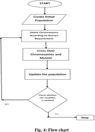
GA is a stochastic global adaptive search optimization technique based on the mechanism of natural selection [11]. It is a heuristic mimicking the natural evolution process and is routinely used to generate useful solutions of an optimization problem. GA has been recognized as an effective and efficient technique to solve optimization problems. Compared with other optimization techniques, such as simulating annealing and random search method techniques, GA is expected to be superior in avoiding local minima, which is a significant issue in case of non-linear systems [12].We know that the performance parameter for any DC Motor can be optimized by employing the PID Controller and then optimizing or lowering the error functions. In the present work, GA is used to derive the PID Controller parameters by optimizing the error in the DC Motor angular velocity.The flow chart presented in Fig. 4 below represents real implementation of GA so as to optimize the relative output of the parameters which are responsible for the motor control and hence the velocity / speed control.
A. Genetic Operators
In each generation, genetic operators are applied to select the individuals from current population to create a new population. Generally, three main genetic operators are employed and they are reproduction, crossover and mutation. Using different probabilities for applying these operators, the speed of convergence can be controlled. Crossover and mutation operators must be carefully designed, since their choice greatly affects the performance of whole GA.
B. Reproductions
A part of new population can be created by simply copying without changing the selected individuals from the present population. Also the new population has the chance of selection by already developed solutions. There are number of other selection methods available and it is left to the user to select an appropriate one for each process. All selection methods are based on the same principle, i.e., provides fitter chromosomes to have a larger probability of selection.
Four common methods for selection are:
(i) Roulette Wheel selection (ii) Stochastic Universal sampling (iii) Normalized geometric selection (iv) Tournament selections
C. Crossover
Crossover operator is one of the main operators that are used to produce offspring that are different from their parents but which have inherited a portion of their parent’s genetic material. From this operator, a selected chromosome is split into two parts and recombines with another selected chromosome which has been split at the same crossover point. Typically this operator is applied at a rate of 60% to 80% of the population, at the crossover point and each pair is randomly selected.
D. Mutations
The mutation operator plays a secondary role in the evolution process. It helps to keep the diversity in population by discovering new or restoring lost genetic materials by searching the neighborhood solution space. Despite the fact that mutation can serve a vital role in a GA, it is noted that it occurs with a small probability rate of 0.1% to 10% of the entire population.
IV MODIFIED INTERACTIVE EVOLUTIONARY COMPUTATION
Interactive Evolutionary Computation (IEC) or aesthetic selection is a general term used for method of Evolutionary Computation (EC) that uses human evaluation. Usually human evaluation is necessary when the form of fitness function is not known. The interactive EC is a technology that optimizes the system based on human subjective evaluation. Simply stated, the EC fitness function is replaced by a human. Interactive EC is the optimization technique based on the subjective scale. Humans evaluate the distance between the goal and a system output in psychological space. On the other hand, EC searches in a parameter space. The interactive EC is a system in which both human and EC cooperatively optimize a target system based on mapping relationship between the two spaces. Interactive evolutionary computing is a technique from the class of evolutionary algorithms (EA) whose fitness function is replaced by a human. A human plays the role of fitness function and selects one or more individual(s) which survive(s) and reproduces to constitute a new generation.
A. Evolution Strategy
Search procedures that mimic with natural evolution of the species IN a natural system are coined as Evolutionary strategies [6]. Like GA, they require data based on objective function and constraints, and not the derivatives or other auxiliary knowledge. Evolution Strategies (ESs) were developed by [7], with selection, mutation and a population of size one.
B. Selection
For a given generation, parents and off springs are generated by recombination and mutation. They are sorted according to user defined criteria and the user selects the best to become parents for the next generation.
C. Reproduction
10.15662/ijareeie.2014.0308060
the previous population. Generally, the average fitness of the population is increased as compared to the previous population.
D. Termination
The process of optimization is stopped once a required criterion is achieved. The termination condition can be based on either the number of generations or the solution satisfying an optimum criterion.
E. Modification to IEC
As in automated Evolutionary optimization algorithms, IEC does not use many individuals and is not required to be iterated over many generations. The limitation arises because the decision maker is human and due to human fatigue, the process cannot be iterated over many generations. Hence, MIEC is developed which efficiently searches with a few individuals and a few generations. Moreover, selection of individuals as done by a human is also incorporated in the software in an automatic way by selecting the best four individuals from the population to participate in next generation. The fitness function results are sorted out from a generation and the four individuals with least value of the fitness function are allowed to participate in the next generation. This overcomes the limitation of the human fatigue and iterations over the concept where a few generations can be performed and much better optimizations can be made.
V.SIMULINK MODEL FOR THE COMPLETE SYSTEM
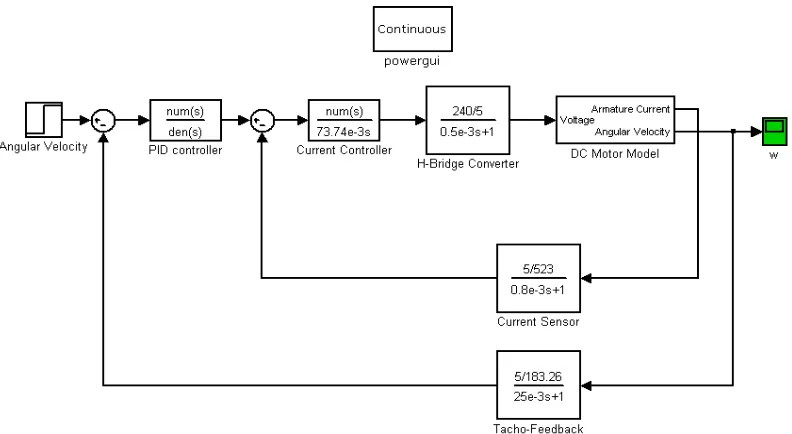
Fig. 5 presents the model developed for control optimization through MIEC or GA. Here, input is the angular output itself which has to be optimized for the predefined parameters. The input is fed to PID Controller which has numerator and denominator. The PID Controller calculates an “error” value based on the difference between a measured process variable and a desired set point and then it attempts to minimize the error by adjusting the process control inputs by choosing one best fitness function among the four best randomly chosen fitness functions.
The output of PID Controller is fed to the current controller which then transfers the output to H-Bridge converter. The H-Bridge converter develops the voltage to be applied across a load in either direction. Enabling of the converter output is forwarded to the DC Motor model which regulates the armature current and its angular velocity. The armature current is then feedback to the current controller through current sensor. And thus the regulated output can be visualized on the output terminal.
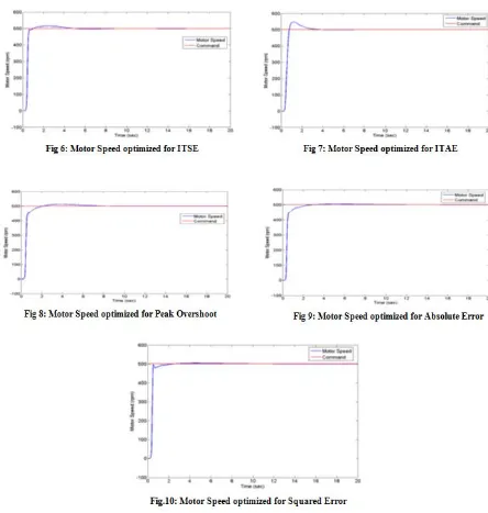
VI.RESULTS OF OPTIMIZATION USING GENETIC ALGORITHM
10.15662/ijareeie.2014.0308060
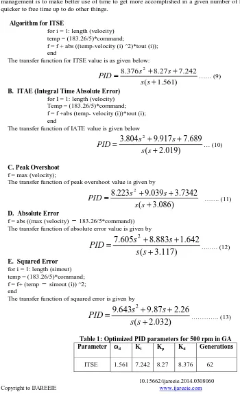
A. ITSE (Integral Time Square Error)
Time Management is the use of a system or method to improve efficiency and effectiveness. This can be accomplished by using the time management system of others or designing their own. The significance of time management is to make better use of time to get more accomplished in a given number of hours or accomplish things quicker to free time up to do other things.
Algorithm for ITSE
for i = 1: length (velocity) temp = (183.26/5)*command;
f = f + abs ((temp-velocity (i) ^2)*tout (i)); end
The transfer function for ITSE value is as given below:
)
561
.
1
(
242
.
7
27
.
8
376
.
8
2
s
s
s
s
PID
…… (9)B. ITAE (Integral Time Absolute Error) for I = 1: length (velocity) Temp = (183.26/5)*command; f = f +abs (temp- velocity (i))*tout (i); end
The transfer function of IATE value is given below
)
019
.
2
(
689
.
7
917
.
9
804
.
3
2
s
s
s
s
PID
… (10)C. Peak Overshoot
f = max (velocity);
The transfer function of peak overshoot value is given by
)
086
.
3
(
7342
.
3
039
.
9
223
.
8
2
s
s
s
s
PID
……. (11)D. Absolute Error
f = abs ((max (velocity)
183.26/5*command)) The transfer function of absolute error value is given by)
117
.
3
(
642
.
1
883
.
8
605
.
7
2
s
s
s
s
PID
…..… (12)E. Squared Error
for i = 1: length (simout) temp = (183.26/5)*command; f = f+ (temp
simout (i)) ^2; endThe transfer function of squared error is given by
)
032
.
2
(
26
.
2
87
.
9
643
.
9
2
s
s
s
s
PID
…………. (13)Table 1: Optimized PID parameters for 500 rpm in GA Parameter ωd Ki Kp Kd Generations
ITAE 2.019 7.689 9.917 3.804 67
Peak
Overshoot 3.086 3.734 9.039 8.223 51 Absolute
Error 3.117 1.642 8.883 7.605 24 Squared
Error 2.032 2.26 9.87 9.643 35
VII.RESULTS OF OPTIMIZATION USING MIEC
10.15662/ijareeie.2014.0308060
The different optimization functions and the resulting PID Controller transfer function are listed below for various types of error models:
1.) ITSE (Integral Time Square Error): It penalizes large errors more than small. This is the cumulative sum of the error which is represented in the form of transfer function as follows:
)
1
(
397
.
0
576
.
4
195
.
4
2
s
s
s
s
PID
………….. (14)2.) ITAE (Integral Time Absolute Error): When there is sum of areas above and below the set-point, this penalizes all errors equally regardless of direction. The ITAE value for the PID can be represented as the following transfer function:
)
1
(
943
.
5
811
.
9
206
.
9
2
s
s
s
s
PID
….…… (15)3.) Absolute Error: It can be represented as the following transfer function:
)
147
.
3
(
823
.
2
s
s
PID
………..…… (16)4.) Squared Error: It can be represented as the following transfer function:
)
1
(
180
.
7
519
.
6
s
s
s
PID
……… (17)5.) Peak Overshoot:
)
905
.
1
(
002
.
1
654
.
2
712
.
1
2
s
s
s
s
PID
Table 2: Optimized PID parameters of MIEC for 500 rpm Parameter ωd Ki Kp Kd Generations
ITSE 1 0.397 4.576 4.195 29
ITAE 1 5.943 9.811 9.206 16
Absolute
Error 3.147 0 2.823 0 10 Squared
Error 1 0 7.180 6.519 3 Peak
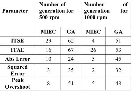
Overshoot 1.905 1.002 2.654 1.712 8 VIII.COMPARATIVE STUDIES BETWEEN MIEC AND GA
Table 3 presented below represents the comparative result analysis between the two evolutionary computational algorithms such as GA and MIEC. The various errors models considered for these purposes are ITSE, ITAE, Peak overshoot, absolute error and squared error. The results presented in the table below are for two different operating conditions i.e., for (i) 500 rpm and (ii) 1000 rpm. The number of generations that are required for convergence for both GA and MIEC are tabulated for different models. For a speed command of 500 rpm, GA requires 62 generations which is reduced to 29 in case of MIEC and for a speed command of 1000 rpm GA requires 51 generations which is reduced to 4 in case of MIEC for ITSE error model. Similarly for other error models also even for the same two different speeds it is observed that lesser number of generations are required in case of MIEC than that of GA.
Table 3: Comparative results for GA and MIEC
Parameter
Number of generation for 500 rpm
Number of generation for 1000 rpm
MIEC GA MIEC GA ITSE 29 62 4 51
ITAE 16 67 26 53
Abs Error 10 24 5 45
Squared
Error 3 35 2 32 Peak
Overshoot 8 51 5 48
From the analysis of above data for the relative error function parameters tabulated confirms that the MIEC based implemented optimization technique likely to provide better performance than the GA implemented control system because it required lesser number generations to converge.
IX. HARMONIC ANALYSIS
The harmonic analyses for various speed profiles have been carried out for both GA and MIEC and the comparative studies are presented for a specific case.
10.15662/ijareeie.2014.0308060
A. Genetic Algorithm results:
B. Modified Interactive Evolutionary Computation Technique results:
The harmonic amplitudes and their order in both voltage and current are estimated using FFT package and are presented in Fig. 21 and 23. Current and voltage both have odd and even harmonics and they are found to having same amplitudes as shown in Figures.
10.15662/ijareeie.2014.0308060
of the harmonics present have almost same amplitude in both cases, but some harmonics amplitudes are slightly reduced or increases as order increases in case of MIEC and GA. But the harmonic content is smaller in MIEC than GA. Therefore we can conclude that performance is better in MIEC than GA.
X.CONCLUSIONS AND FUTURE SCOPE
In the present research work, Evolutionary Computational techniques such as GA and MIEC have been used to realize more effective tuning of a controller so that better optimized condition for the controller has been derived. The results which are obtained shows better optimized values used for the controller tuning and hence the motor performance is enhanced in terms of its stabilization time with reduced oscillations.
The GA based algorithm adopted to tune the controller parameters for various error models mentioned above shows that the optimization of the speed has been achieved with various number of generations required for convergence to obtain the controller parameters. The number of generations required for ITSE model is 62, for ITAE 67, Peak overshoot model requires 51, and absolute error model requires 24 and squared error requires 35 for a command speed of 500 rpm. The respective settling times are found to be 6 seconds, 4 seconds, 8 seconds, 3 seconds and 3 seconds.
The study also has been carried out for another speed command of 1000 rpm. The optimization results derived shows that number of generations required for optimization varies with the type of error model used. But the trend in terms of generation required (higher or lower) remains the same. The respective settling times are found to be 7 seconds, 2 seconds, 13 seconds, 15 seconds and 4 seconds. For higher speed in some cases of error models found to be larger but at the same time in same case it is reduced.
Hence, we can conclude that, since lesser number of generations is required for absolute error model for both speed, it takes less time to establish the steady state rather quickly than any other type of model. But at the time of transition of speed command, the drive had shown smaller percentage of overshoot and undershoots under specified operating conditions when compared to other models. Therefore, based on the results we conclude that the absolute error model is the best model for optimization and can be used for the velocity control of DC Motor.
On the other hand MIEC technique used for tuning the controller. The results obtained for various error model based optimization mentioned above such as integral time squared error (ITSE), Integral time absolute error (ITAE), peak overshoot error, absolute error and squared error had shown that the number of generations required to stabilize the controlled parameters are drastically reduced. For ITSE model it reduces from 62 to 29, 67 to 16 for ITAE error model, 51 to 8 for peak overshoot, for absolute error model from 24 to 10 and for squared error model it reduces from 35 to 3 for a command speed of 500 rpm. The respective settling times are found to be 2 seconds, 5 seconds, 2 seconds, 3 seconds and 2 seconds. This shows that faster stabilization is obtained through MIEC.
The study of optimization for another speed command of 1000 rpm also has been carried out using MIEC. This study reveals that the number of generations required for convergence reduces for MIEC as compared to GA for the same operating conditions. The number of generations is reduced from 51 to 4 for ITSE model, 53 to 26 for ITAE model, 45 to 5 for peak overshoot model, 35 to 2 for absolute error model and 48 to 5 for squared error model. The respective settling times are found to be 12 seconds, 8 seconds, 4 seconds, 3 seconds and 3 seconds.
Hence, the number of generations required in MIEC are very much lesser as compared to GA to stabilize the controller parameters which results in faster response. Also at the transition of speed command the percentage overshoot and undershoots of developed speed found to be smaller as compared to GA. Based on these results, we can conclude that MIEC provides better and faster response than that of GA based PID tuning controller for the same type of model.
Hence, for a comparative study to evaluate the performance of GA and MIEC, velocity control of a DC Motor is performed using absolute Error model optimization. The analysis of velocity control for different speed profiles has been performed for such as trapezoidal, square and multiple transition speed commands. The control established more precisely both in the case of GA and MIEC implementation as compared to other types of generally used optimization techniques. From the results obtained conclusions can be drawn that stabilization obtained from MIEC based control is superior as compared to GA based control even though both can provide better control than other conventional methods. Therefore, the conclusion is that MIEC is capable of better optimizing and provides faster stabilization which can be used to drive control also.
REFERENCES
[1.] Madan Gopal, I. J. Nagrath, “Control Systems Engineering,” 5th
edition, New Age International, 2010.
[2.] Ramesh C. Panda, “Introduction to PID Controllers - Theory, Tuning and Application to Frontier Areas,” Publisher: InTech, Chapters published February 29, 2012.
[3.] Zhang, J. and Morris, A. J. (1995). “Fuzzy neural networks for nonlinear systems modeling,” IEE Proceeding Control Theory and Applications, vol. 142, pp. 551-561.
[4.] Eric Poulin, Andre Pomerleau, Andre Desbienst, Daniel Hodouins, “Development and Evaluation of an Auto-tuning and Adaptive PID
Controller,” Auromatica, Vol. 32, No. 1, pp. 71-82, 1996.
[5.] Pierre-Olivier Malaterre, David C. Rogers, Jan Schuurmans, “Classification of Canal Control Algorithms, Journal of Irrigation and
Drainage Engineering,” Vol. 124, Issue 1 / technical papers.
[6.] Jin Hyun Park, Su Whan Sung, In-Beum Lee, “An Enhanced PIC Control Strategy for unstable Processes,” Auromatica, Vol. 34, No. 6, pp. 751-756, 1998.
[7.] M.M. Hand, M.J. Balas, “Non-Linear and Linear Model Based Controller Design for Variable-Speed Wind Turbines,”Engineering Conference San Francisco, California, July 18-23, 1999.
[8.] Horikawa, S., Furuhashi T. and Uchikawa Y., “On fuzzy modeling using fuzzy neural networks with the back-propagation algorithm,” IEEE Transactions on Neural Networks, vol. 3, pp. 801-806, 1992.
[9.] Chen, Y.C. and Teng C.C., “A model reference control structure using a fuzzy neural network. Fuzzy Sets and Systems,” vol.73, pp. 291-
312, 1995.
[10.] Zhang J. and Morris, A. J., “Fuzzy neural networks for Non-Linear systems modeling,” IEEE Proceeding – Control Theory and Applications, vol. 142, pp. 551-561, 1995.
[11.] Cao, S.G., Rees, N.W., and Feng G., “Analysis and design for a class of complex control systems. Part I:Fuzzy modeling and
identification Automatica,” vol. 33, pp. 1017-1028, 1997.
[12.] Wai, R.J. and Lin, F.J., “A fuzzy neural network controller with adaptive learning rates for Non-Linear slider-crank mechanism.
Neurocomputing,” vol. 20, pp. 295-320, 1998.
[13.] Gao, F., Wang, F., and Li, M., “An analytical predictive control law for a class of Non-Linear processes,” Industrial and Engineering Chemistry Research, vol. 39, pp. 2029-2034, 2000.
[14.] Hsu, C.F., Chen, G.M., and Lee, T.T., “Robust intelligent tracking control with PID-type learning algorithm,”Neurocomputing, In press, 2007.
[15.] Atkeson, C.G., Moore, A.W., and Schaal, S., “Locally weighted learning,” Artificial Intelligence Review, vol.11, pp. 11-73, 1997.Cybenko, G. S. Bittanti and G. Picci, “Identification, adaptation, learning: in the science of learning models from data,” Springer, New York, pp. 423-434, 1996.
[16.] Lu, J., Chen, G., and Ying, H., “Predictive fuzzy PID control: Theory, design, and simulation,” Information Sciences, vol. 137, pp. 157-187, 2001.
[17.] Chen, J.H. and Huang, T.C., “Applying neural networks to on-line update PID Controller s for Non-Linear process control,” Journal of Process Control, vol. 14, pp. 211-230, 2004.
[18.] Sun, L., Mei, T., yao, Y., Cai, L., and Meng, M.Q.H., “PID controller based adaptive GA and neural networks,” Proceedings
of the 6th World Congress on Intelligent Control and Automation, Dalian, China, pp. 6564-6568, 2006.
[19.] Chang, W.D., Hwang, R.C., and Hsieh, J.G., “A self-tuning PID control for a class of Non-Linear systems based on the Lyapunov