Comparative Analysis of Voltage and Reactive
Power Control in Distribution System with
and Without Distributed Generation
Varun Dev Mishra1 Dr. Jyoti Shrivastav2
PG Student, Department of Electrical Engineering, SHIATS-DU Naini, Allahabad, India1
Assistant Professor, Department of Electrical Engineering, SHIATS-Deemed University, Allahabad India.2
ABSTRACT:- Development of any country depends upon the energy resources of that country by which energy can be extracted in the form of electrical power. Various kind of conventional and non conventional energy resources are used on the basis of availability and technical feasibility of system. With increase the demand of an electrical energy create many problems in electrical power quality, like Sag and Swell in the Voltage level, also Swing in the Frequency. In this paper we have discussed about the Distributed Generation (wind power generation), interconnection of wind power system with conventional power station to improve the voltage profile and power factor using HVDC converter stations. HVDC converter station consists of rectifier and inverter station.
KEYWORDS: HVDC( High Voltage Direct Current), Wind Turbine ,Non-conventional energy recourse, Reactive power, Distributed Generation.
I.INTRODUCTION
This Demand of electricity is ever increasing. Over the past decades, the increment in electricity demand has been largely balanced by capacity development of conventional generations. However, further capacity development of these generations to balance demand of electricity is considered unsustainable mainly due to limited resource of their primary energies and due to negative impacts they introduce to the environment. In order to meet the future demand of electricity as well as to replace ageing existing generations, a number of new generation technologies i.e. wind power, solar thermal, solar photovoltaic, biomass, biodiesel, tidal power and wave power, which make use of the renewable energy resources e.g. wind, solar, biomass, biodiesel, tidal and wave energy as their primary energy, have been developed.
Distribution generations (DG) are electric power generators that produce electricity at a site close to customers or that are tied to an electric distribution system. Distributed generators include, but are not limited to synchronous generators, induction generators, reciprocating engines, micro turbines (combustion turbines that run on high-energy fossil fuels such as oil, propane, natural gas, gasoline or diesel), combustion gas turbines, fuel cells, solar photovoltaic, and wind turbines.
Figure 1: Distribution generation technology
Benefits of Distributed Generating Systems
Distributed Generation:
Has a lower capital cost because of the small size of the DG.
May reduce the need for large infrastructure construction because the DG can be constructed at the load location.
If the DG provides power for local use, it may reduce pressure on distribution and transmission lines.
With some technologies, produces zero or near-zero pollutant emissions over its useful life.
With some technologies such as solar or wind, it is a form of renewable energy.
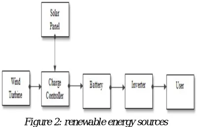
The main advantage of renewable energy systems (RES) is no fossil fuels involved because it is free like sun and wind. This decreases the operational cost of renewable energy systems and reduces operational risks. The major drawback is the initial investment in renewable energy systems, which is often larger than for non-RES. For instance, a gas turbine system may be built for 500 EUR per kW, while for a wind turbine the investment is more than 900 EUR per kW.
Figure 2: renewable energy sources
Wind Power Technology
Wind power technology captures kinetic energy in wind speed for electricity generation by utilizing a number of wind turbines. These wind turbines are installed in a particular area where the potency of wind energy is high and are linked together forming a WPP. The power generated by the wind turbines is aggregated and delivered to the grid. Depending on their location e.g. onshore or offshore, their connection to the grid may directly or through a dedicated transmission. However, variability in wind speed introduces variability in WPP power both over short period e.g. minutes and long period e.g. hours or days. When a number of WPPs are connected to a grid, the variability in their power may complicate dispatch of other types of generation. The variability in WPP power over short period may decrease when the number of utilized wind turbines increases. The variability over long period however, may decrease only when location of the WPPs are dispersed over a wide area.
Figure 3 Global installed capacity of wind power, 2007-2018
Over the past decade, development of wind power in the world is rapidly growing (Figure 1.3). This rapid development is mainly influenced by technological advancement which has made possible to increase its turbine size to produce electricity at cost level approaching present market price. This factor also influences the increased size of WPP from utilizing tents of wind turbines to groups of up to hundreds of wind turbines. Moreover, its possibility to be installed offshore allows for development with capacity comparable to that of the conventional generation with less impact to the local society.
Figure 4 Wind power plants in India
HVDC
an AC transmission line over short distances. For transmitting high power over long distances (several hundred km) HVDC offers the following advantages:
• only two conductors are needed (or even one conductor if the ground is used as return)
• better system stability, i.e. two networks that are not synchronized or do not have the same frequency can be connected.
II.MATHEMATICAL MODELLING
Operating Principle of the Wind Turbine DFIG
The mechanical power and the stator electric power output are computed as follows:
= (3.1) = (3.2)
Pm Mechanical power captured by the wind turbine and transmitted to the rotor Ps Stator electrical power output
Pr Rotor electrical power output Pgc Cgrid electrical power output Qs Stator reactive power output Qr Rotor reactive power output Qgc Cgrid reactive power output Tm Mechanical torque applied to rotor
Tem Electromagnetic torque applied to the rotor by the generator Wr Rotational speed of rotor
Ws Rotational speed of the magnetic flux in the air-gap of the generator, this speed is named synchronous speed. It is proportional to the frequency of the grid voltage and tothe number of generator poles.
J Combined rotor and wind turbine inertia coefficient For a loss less generator the mechanical equation is:
= − (3.3)
In steady-state at fixed speed for a loss less generator
= (3.4) = + (3.5)
It fallows that
= − = − =− − =− =− (3.6)
where s is defined as the slip of the generator:
The schematic diagram and the vector-based equivalent circuit of a HVDC converter station station in the synchronous dq reference frame is shown in Fig.2.
fig.6 Schematic diagram and equivalent circuit of a VSC station
Vc=Vs-RcIc-jωLcIc-Lcdi/dt
I
c=I
s-
jω
sω
fV
s-C
fdV
s/dt
P
s+jQ
s=3/2V
sI
sP
dc=P
s- I
cR
c=V
dcI
dcC
fdV
s/dt
s=I
s-I
c-
jωC
fV
sRc=total loss of vsc, Lc=filter inductor,Cf=filter capacitor III.RESULTANDDISCUSSION
A. Sending end voltage waveform(Vac1)
B. Load end voltage waveform without wind power (Vac2):
C. Load end voltage waveform with wind power (Vac3):
D. DC voltage transmitted between station1 and station 2.
IV.CONCLUSION
REFERENCES
[1] Yuan Fu1,a, Yi Wang1,b, Yingli Luo,c, and Xiangyu Zhang,c, “Operation and Coordinated Control of Multi-terminal VSC-HVDC Transmission System for Wind Power Generation”,in International Conference on Power and Energy Systems Lecture Notes in Information Technology,
[2] N. Ahmed, A. Haider, D. Van Hertem, Z. Lidong, and H. P. Nee, "Prospects and challenges of future HVDC SuperGrids with modular multilevel converters," in Power Electronics and Applications (EPE 2011), 2011, pp. .
[3] D. Van Hertem and M. Ghandhari, "Multi-terminal VSC HVDC for the European supergrid: Obstacles," Renewable and Sustainable Energy Reviews, vol. 14, pp. 3156-3163, 2010.
[4] L. Xu, L.Yao, Bazargan, M., “DC grid management of a multi-terminal HVDC transmission system for large offshore wind farms.” Proc. First SUPERGEN Conf., Nanjing, China, April 2009.
[5] Temesgen M. Haileselassie, Marta Molinas. Tore Undeland, “Multi-Terminal VSC-HVDC System for Integration of Offshore Wind Farms and Green Electrification of Platforms in the North Sea,” Proc. Nordic Workshop on Power and Industrial Electronics, June, 2008.
[6] L. Xu, L.Yao, Bazargan, M., Williams, B.W., “Control and operation of multi-terminal dc systems for integrating large offshore wind farms.” Proc. Seventh Int. Workshop on Large-Scale Integration of Wind Power and Transmission Networks for Offshore Wind Farms, Spain, May 2008.
[7] Chen Z.," Compensation schemes for a SCR converter in variable speed wind power systems", Power Delivery, vol. 19, pp. 813-821,2004. [8] Bozhko S., Asher G., and Risheng L.," Large Offshore DFIG-Based Wind Farm With Line-Commutated HVDC Connection to the Main Grid:
Engineering Studies", Energy Conversion, vol. 23, pp. 119-127,2008.
[9] H. Chong A.Q., Huang and M.E. Baran," STATCOM Impact Study on the Integration of a Large Wind Farm into a Weak Loop Power System", Energy Conversion, vol. 23, pp. 226-233,2008.
[10] Dawei X., Li R., and Bumby J.R.," coordinated control of an HVDC link and doubly fed induction generators in a large offshore wind farm", Power Delivery, vol. 21, pp. 463-471,2006.