International Journal of Research (IJR)
e-ISSN: 2348-6848, p- ISSN: 2348-795X Volume 2, Issue 08, August 2015Available at http://internationaljournalofresearch.org
Available online:http://internationaljournalofresearch.org/ P a g e | 101
Flicker mitigation and Voltage Quality Improvement in WP
using IPC and ESS
Viswanath Reddy.SN; Dr. Samalla Krishna & Ms. Katkuri Laxmi Chaitanya
1Electrical Power Systems in Tudi Narsimha reddy Institute Of Science & Technology, Bibinagar, Nalgonda,
Telangana, INDIA .
2Jawaharlal Nehru Technological University Kakinada.
3
Graduate and Post Graduate engineering courses
Abstract: -
The wind power (WP) penetration with the distributed networks associated with an adverse impact on the voltage quality (VQ) due to the wind shear& tower shadow effects on WP which results in flickers in the WP. This paper proposes a new topology penetration of the WP with the Energy Storage System (ESS) and operating with Individual Pitch Control (IPC) Method for improving the VQ. The installation of an ESS is a possible VQ remedy in WP flicker problems, the proposed ESS control and management are tailored to that purpose such that the ESS offsets the flicker-producing fluctuations in the generated WP. The power sizing of ESS is defined by the estimated turbulence intensity and wind speed average at the installation site. A 2 MW capacity wind generator of a doubly fed induction generator (DFIG) type is employed as the source of WP and simulations are conducted on a simplified test system, as well as a detailed 25 kV distribution network on which results are compared with acknowledged reactive power flicker mitigation approaches and verified by prototyping in Mat-Lab simulink Soft ware and the simulated results are verified.
Index terms – Flickers, Flicker Mitigation, Energy storage system, Wind Power, Voltage Quality, Individual Pitch control
I.INTRODUCTION
The penetration of wind power (WP) in distribution networks is challenged by capacity constraints imposed by power quality (PQ) dictated criteria. More specifically, a major concern in distribution the networks are VQ that experiences deterioration after WP connection due to the fluctuating nature of the generated active power in the WP. From a voltage quality perspective, WP fluctuations occur in two frequency ranges: 1) low-frequency range prompting changes in the steady-state voltage level; and 2) high-frequency range
resulting in a flicker contribution. This body of work deals with the latter. Flicker emission of a wind generator (WG) refers to the dynamic voltage changes occurring in the range of 0.05–42 Hz in 120 V/60 Hz systems as a result of the interconnection of the WG to the grid. The flicker emission stems from sources detailed in [1] and incorporated in the WG model in this paper.
Conventional mitigation of WP flicker severity is achieved by control of the reactive power flow to counteract the active WP fluctuations voltage impacts either through control of the WG converters or the use of a flexible ac transmission system (FACTS) device [2], [3]. Yet, the use of reactive power is limited by its availability [4], [5], the grid codes limitations on WGs reactive power control capability [6] and is highly restrained by the network
reactance-to-resistance (X/R) ratio [1], [7] that are all
decisive factors in determining the feasibility of reactive power control as a flicker mitigation approach.
International Journal of Research (IJR)
e-ISSN: 2348-6848, p- ISSN: 2348-795X Volume 2, Issue 08, August 2015Available at http://internationaljournalofresearch.org
perspective was yet to be posed as no power quality benchmark assessment was in question.
This paper complements the aforementioned studies by the following contributions: 1) proposing a combined control/ management algorithm for a SC-based short-term ESS to allay the WP short-term power quality concern of voltage flicker; and 2) proposing an ESS power sizing methodology as a function of the wind speed average and turbulence intensity at the installation site.
An open-loop pitch control is used in [6] and [8] to investigate the flicker emission in high wind speeds; however, the pitch actuation system (PAS) is not taken into account. Because the pitch rate and the time delay of the PAS make great contributions to the results of the flicker emission of variable-speed wind turbines, it is necessary to take these factors into consideration. In recent years, IPC which is a promising way for loads reduction has been proposed [9]–[11], from which it is notable that the IPC for structural load reduction has little impact on the electrical power
The IEC flicker meter described in [19] is employed for flicker measurement and flicker measurements are conducted in accordance with [20]
with the short-term flicker index ―Pst‖ being the
comparison benchmark.
Fig1. Scheme of the DFIG-based wind turbine system
II. WIND TURBINE CONTROL AND FLICKER EMISSION ANALYSIS
For a DFIG-based variable speed wind turbine, the control objective is different according to different wind speed. In low wind speed, the control goal is to keep the tip speed ratio optimum, so that the maximum power can be captured from the wind. In high wind speed, since the available power is beyond the wind turbine capacity, which could overload the system, the control objective is to keep the extracted power constant at its rated value.
A. Control of Back-to-Back Converter
Vector control techniques are the most commonly used methods for a back-to-back converter in a wind turbine system. Two vector control schemes are illustrated, respectively, for the Rotor side converter (RSC) and Grid side converter
(GSC), as shown in Fig. 1, where Vs , and Is are the
stator voltage and current, ir is the rotor current, vg
is the grid voltage, Ig is the GSC currents, Wg is the
generator speed, E is the dc-link voltage, Ps ref , and
Qs ref are the reference values of the stator active
and reactive power, Qr ref is the reference value of
the reactive power flow between the grid and the
GSC, Eref is the reference value of the dc-link
voltage, C is the dc-link capacitor.
The vector control objective for RSC is to implement maximum power tracking from the wind by controlling the electrical torque of DFIG. The
reference value of the generator speed ω ref is
obtained via a lookup table to enable the optimal tip speed ratio. The objective of GSC is to keep the dc-link voltage constant, while keeping sinusoidal grid currents. It may also be responsible for controlling the reactive power flow between the grid and the
grid-side converter by adjusting Qg ref . Usually, the
values of reactive power of RSC and GSC are set to zero to ensure unity power factor operation and reduce the current of RSC and GSC [1].
B. Pitch Control
Normally, pitch control is used to limit the aerodynamic power captured from the wind. In low wind speeds, the wind turbine should simply try to produce as much power as possible, so there is no need to pitch the blades. For wind speeds above the rated value, the pitch control scheme is responsible for limiting the output power. The PI controller used for adjusting the pitch angles works well in normal operation, however, the performance of the pitch control system will degrade when a rapid change in wind speed from low to high wind speed is applied to the turbine rotor. It takes a long time for a positive power error contribution to cancel the effects of the negative pitch angle contribution that has been built up from integration of these negative power errors.
The integrator anti windup scheme is implemented which the anti windup term with gain
Kaw is fed back to the integrator only. This prevents
the integrated power error from accumulating when the rotor is operating in low wind speeds. The value
for Kaw may be turbine dependent. When the pitch
International Journal of Research (IJR)
e-ISSN: 2348-6848, p- ISSN: 2348-795X Volume 2, Issue 08, August 2015Available at http://internationaljournalofresearch.org
C. Flicker Emission in Normal Operation
As discussed in Section I, flicker emission of a grid-connected wind turbine system is induced by voltage fluctuations which are caused by load flow changes in the network, so it is necessary to analyze the electrical power to the grid. Therefore, a simulation is conducted when the mean wind speed is 13 m/s based on the model as shown in Fig. 1.
The parameters of the wind turbine system are given in the Appendix. In this case, the turbine speed is around 0.345 Hz, which corresponds to the 3p frequency of 1.035 Hz, which is in conformation with the spectrum. It is clearly seen that in addition to the 3p frequency, 6p, 9p, and higher frequencies are also included in the generator output power. These components will induce voltage fluctuations and flicker emission in the power grid.
Further, the flicker emission of a variable-speed wind turbine with DFIG is studied. The level of flicker is quantified by the short-term flicker severity
Pst , which is normally measured over a 10-min
period. According to IEC standard IEC 61000-4-15, a flicker meter model is adopted to calculate the
short-term flicker severity Pst [6], [15], [16].
III. STORAGE SYSTEM CONFIGURATION
A. Centralized Versus Distributed Topology
Contemporary WGs are typically featured either as DFIGs or fully rated converter synchronous generators. In the fully rated converter WGs, the total WP generation traverses the fully rated converter. Conversely, the converter is rated at 20– 30% of the machine rating in DFIGs. Therefore, if storage is to be connected to the machine converter dc link as in [14] and [21], converter imposed size limitations are placed on the storage unit in case of the DFIG (20–30% of machine rating). The grouping effect and consequent reduction in power rating in multi-WG assemblies is also an advantage that centralized storage can capitalize on. Considering the previous factors, a centralized ESS is assumed for generalization purposes and two power electronic converters are employed: an ac/dc converter and a dc/dc converter (see Fig. 2).
Fig.2. Energy storage system
A. AC/DC Voltage-Source Converter (VSC)
The control of the VSC is done in decoupled
two-coordinate dq frame such that active and
reactive powers are controlled independently. The basic equations describing the control action were studied extensively in literature and can be found in [22].
The VSC is controlled such that a constant dc-link voltage is maintained with the dc/dc converter assuming control of the storage unit power flow.
B. DC/DC Converter
A two-quadrant converter controls the flow of power from and to the storage unit. When switch T1 (see Fig. 2) is ON, the dc-link voltage is imposed on the storage unit branch and the flow of power is from the point of common coupling (PCC) to the storage unit, while if T2 is ON, the current reverses direction and the voltage across the storage unit branch is zero. If switch T2 is switched off, the current flowing in the switch is conducted through D2 until it drops to zero transferring power from the storage unit to the PCC. The average voltage across the storage unit branch and the storage unit current is governed by
Where Vsc is the average storage branch
voltage, D is the duty cycle, Vdc is the dc-link
voltage, Isc is the SC current,and Is is the average
input current to the dc/dc converter. Due tothe high
computational burden of the required Pst –
calculation 10-min simulation runs, (1) and (2) are
used to link the dc/dcconverter to the dc link in an
average switching model in a subsetof the presented
results.
International Journal of Research (IJR)
e-ISSN: 2348-6848, p- ISSN: 2348-795X Volume 2, Issue 08, August 2015Available at http://internationaljournalofresearch.org
The proposed control for the dc/dc converter is realized in two levels: 1) a level at which the storage duty cycle is controlled (current control loop); and 2) a level at which the storage unit power consumption is controlled (power control loop).
A. Current Control Loop
A current control loop acts on the dc/dc converter switches to track the SC reference current setting. The SC is represented by a capacitance and a series resistor as done in [3] and [4] and is discharged through an inductor. By considering that representation and the switching states of the dc/dc converter of Fig. 2 the transfer function represents the duty cycle–current relationship or the controlled plant for the current control loop
Where Δisc , Δd are small changes in the
storage branch current and duty cycle, respectively,
C is the SC capacitance,
R is its series resistance, and L is the discharging
inductor inductance. The characteristic design equation in that case for the current control loop is described by
1 + PWMgainP1 (s) = 0
Where PWM gain is the gain introduced by the PWM switching. The current control loop transfer
function including the current controller C1 (s)is of
the form of
The current control loop responds to a current reference set by an outer control loop (power control loop) whose controlled plant and characteristic equation are defined by a simultaneous Flicker mitigation and storage management control scheme.
B. Power Control Loop
The active power command to the storage unit is formulated such that two purposes are fulfilled: 1) offsetting undesired WP fluctuations at the PCC and
is achieved by a flicker power command P flicker;
and 2) maintaining a minimum level of stored energy in the unit to allow the sought offsetting and is achieved by a management charge/discharge
power command P char−disch. 1) Flicker Power
Command: Pflicker is obtained from the
Measured Pw by means of a high-pass filter with
a time constant τ1 (3.18 s) presenting a cut-off
frequency of 0.05 Hz (start of the flickering range)
2) Management Power Command
Pchar−disch is a storage management command
in which changes should occur at a frequency below the start of the flickering range providing control to the storage unit state of charge (SoC) and avoiding
interference with P flicker and presenting no flicker
contribution. In order to generate Pchar− disch, a
threshold SC voltage Vsc threshold serves as a
reference point to the management scheme to constantly maintain a corresponding level of energy
Esc threshold in the storage unit according to (16).
Esc threshold and therefore Vsc threshold can be
defined by the ratio of a likely positive WP change (energy to be charged) to a likely negative WP change (energy to be discharged).
Fig.3. Small-signal block diagram for the super capacitor control loops.
C. Controller Limits and Design Procedure
A commercial SC cell [13] is the basis of the presented data. The rated voltage of the cell is 400 V with a capacitance of 0.58 F and an equivalent series
resistance of 0.6 Ω. The different parameters of the
storage unit and accompanying control limits are specified as follows.
1) Voltage Limits: The maximum voltage is
determined by the dc-link voltage Vdc and the
minimum voltage is controlled by the limits on the duty cycle and the converter and is determined in
this work by limiting the power loss in R occurring
at Imax to 0.1 Pres .
2) Capacitance: The equivalent capacitance of all series and parallel cells is determined by the energy rating of the storage unit and the operating voltage limits
3) Current Limits: The maximum current Imax occurs as the rated power is delivered to the storage
International Journal of Research (IJR)
e-ISSN: 2348-6848, p- ISSN: 2348-795X Volume 2, Issue 08, August 2015Available at http://internationaljournalofresearch.org
V. SIMULATION RESULTS
To thoroughly verify the proposed ESS operation, the following sets of simulations were
conducted: Simulations 1—ESS performance
verification and parameter sensitivity analysis on a single 2 MW DFIG unit connected to a simplified equivalent impedance network as a bases case, Simulations 2—testing of three storage-equipped wind farm integration scenarios to a detailed 25 kV North American network (WP capacities of 6, 8, and
10 MW) and Simulations 3—real-time prototyping
of a sample subset of Simulations 2 in a real-time
simulation platform to validate the real-time performance of the ESS control algorithm. The WG unit parameters are shown in Table I.
Fig.4.Mat lab simulation Circuit
Fig5. Energy storage system
ESS operation (super capacitor side):
The ESS control performance was observed by recording the ESS active power components as well as the tracking error fed to the power controller.
Similarly, the current measurements were performed in the SC branch as well as one phase of the VSC; the results are shown in Fig. 6
The following are the mat lab simulated results as follows
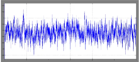
Fig.6.a. Filtered flicker power command
Fig.6.b Super capacitor current
Fig.6.c. Super capacitor voltage
Fig. 6.d. PCC voltage profile.
VI. CONCLUSION
International Journal of Research (IJR)
e-ISSN: 2348-6848, p- ISSN: 2348-795X Volume 2, Issue 08, August 2015Available at http://internationaljournalofresearch.org
flicker problem in the WP. It was shown that a power sizing methodology based on wind speed average and turbulence intensity is appropriate for alleviating the voltage impacts of the flicker-producing changes in the generated WP. A filtering based control algorithm was shown effective in both alleviating the WP flicker severity and properly managing the ESS SoC. The ESS was found to have a superior flicker mitigation capability to that of the reactive power control approaches. Nevertheless, the degree of superiority that the ESS presented was shown to be tied to the connected WP capacity and approximations assumed in the power-factor-based flicker mitigation approaches.
The choice of a flicker mitigation approach should thus be contemplated in light of the planned WP capacity and taking the network impedance and the operative grid code requirements into consideration. And the MAT LAB Simulation results verified.
REFERENCES
[1] M. Ammar and G. Joos, ―The impact of distributed wind generators reactive power behavior
on flicker severity,‖ IEEE Trans. Energy Convers.,
vol. 28, no. 2, pp. 425–433, Jun. 2013.
[2] S. Tao, C. Zhe, and F. Blaabjerg, ―Flicker study on variable speed wind turbines with doubly fed
induction generators,‖ IEEE Trans. Energy
Convers., vol. 20, no. 4, pp. 896–905, Dec. 2005. [3] H. Chong, A. Q. Huang, M. E. Baran, S. Bhattacharya, W. Litzenberger, L. Anderson, A. L. Johnson, and A.-A. Edris, ―STATCOM impact study on the integration of a large wind farm into a weak
loop power system,‖ IEEE Trans. Energy Convers.,
vol. 23, no. 1, pp. 226–233, Mar. 2008.
[4] A. Keane, L. F. Ochoa, E. Vittal, C. J. Dent, and G. P. Harrison, ―Enhanced utilization of voltage
control resources with distributed generation,‖ IEEE
Trans. Power Syst., vol. 26, no. 1, pp. 252–260, Feb. 2011.
[5] M. Z. Sujod, I. Erlich, and S. Engelhardt, ―Improving the reactive power capability of the DFIG-Based wind turbine during operation around
the synchronous speed,‖ IEEE Trans. Energy
Convers., vol. 28, no. 3, pp. 736–745, Sep. 2013. [6] Requirements for the Interconnection of Distributed Generation to the Hydro-Qu´ebec Medium-Voltage Distribution System, 2009.
[7] W. Hu, Z. Chen, Y. Wang, and Z. Wang, ―Flicker mitigation by active power control of variable-speed wind turbines with full-scale
back-toback power converters,‖ IEEE Trans. Energy
Convers., vol. 24, no. 3, pp. 640–649, Sep. 2009. [8] F. Sharkey, J. MacEnri, E. Bannon, M. Conlon, and K. Gaughan, ―Resource-induced voltage flicker
for wave energy converters- assessment tools,‖ IET
Renew. Power Gener., vol. 7, no. 6, pp. 623–630, Nov. 2013.
[9] A. Blavette, D. L. O’Sullivan, R. Alcorn, T. W. Lewis, and M. G. Egan, ―Impact of a medium-size wave farm on grids of different strength levels,‖ IEEE Trans. Power Syst., vol. 29, no. 2, pp. 917– 923, Mar. 2014.
[10] Y. Zhang, Z. Chen,W.Hu, andM.Cheng, ―Flicker mitigation by individual pitch control of
variable speed wind turbines with DFIG,‖ IEEE
Trans. Energy Convers., vol. 29, no. 1, pp. 20–28, Mar. 2014.
[11] H. Emanuel, M. Schellschmidt, S.Wachtel, and S. Adloff, ―Power quality measurements of wind energy converters with full-scale converter
according to IEC 61400–21,‖ in Proc. 10th Int.
Elect. Power Quality UtilizationConf., 2009, pp. 1– 7.
[12] G. O. Cimuca, C. Saudemont, B. Robyns, and M. M. Radulescu, ―Control and performance evaluation of a flywheel energy storage system
associated to a variable speed wind generator,‖ IEEE
Trans. Ind. Electron., vol. 53, no. 4, pp. 1074–1085, Jun. 2006.
[13] L. Wei, G. Joos, and J. Belanger, ―Real-time simulation of a wind turbine generator coupled with a battery supercapacitor energy storage system,‖ IEEE Trans. Ind. Electron., vol. 57, no. 4, pp. 1137– 1145, Apr. 2010.
[14] C. Abbey and G. Joos, ―Supercapacitor energy
storage for wind energy applications,‖ IEEE Trans.
Ind. Appl., vol. 43, no. 3, pp. 769–776, May/Jun. 2007.
[15] A. M. Gee, F. V. P. Robinson, and R. W. Dunn, ―Analysis of battery lifetime extension in a small-scale wind-energy system using supercapacitors,‖ IEEE Trans. Energy Convers., vol. 28, no. 1, pp. 24– 33, Mar. 2013.
[16] P. Thounthong, ―Model based-energy control of a solar power plant with a supercapacitor for
grid-independent applications,‖ IEEE Trans. Energy
Convers., vol. 26, no. 4, pp. 1210–1218, Dec. 2011. [17] C. Abbey, K. Strunz, and G. Joos, ―A knowledge-based approach for control of two-level
energy storage for wind energy systems,‖ IEEE
Trans.Energy Convers., vol. 24, no. 2, pp. 539–547, Jun. 2009.
[18] A. Esmaili, B. Novakovic, A. Nasiri, and O. Abdel-Baqi, ―A hybrid system of Li-Ion capacitors and flow battery for dynamic wind energy support,‖ IEEE Trans. Ind. Appl., vol. 49, no. 13, pp. 1649– 1657, Jul./Aug. 2013.
[19] IEEE Recommended Practice-Adoption of IEC
61000\ 4-15:2010 Electromagnetic Compatibility (EMC)-Testing and Measurement Techniques- Flickermeter-Functional and Design Specifications,
International Journal of Research (IJR)
e-ISSN: 2348-6848, p- ISSN: 2348-795X Volume 2, Issue 08, August 2015Available at http://internationaljournalofresearch.org
[20] Wind Turbine Generator Systems Part 21:
Measurement and Assessment of Power Quality Characteristics of Grid Connected Wind Turbines, IEC
Standard 614000-21, 2001.
S.N.Viswanath Reddy student Graduated in B.Tech EEE in the year 2010 from Narayana Engineering College, Gudur, Nellore, and Andhrapradesh, India. Currently He pursuing M.Tech Graduation in Electrical Power Systems in Tudi Narsimha reddy Institute Of Science & Technology, Bibinagar, Nalgonda, Telangana, INDIA .Research interest in Electrical Power Systems, Power Electronics, Renewable Energy Systems.
Dr.Samalla Krishna working as Professor in Tudi
Narasimha Reddy Institute of Technology & Sciences. He received his Ph.D from Jawaharlal Nehru Technological University Kakinada. He has 12 years of experience in the teaching and research field. He served as an academic supervisor to more than 300 Bachelor Degree dissertations towards the award of Undergraduate Degree and He has published more than 5 research papers in reputed International Journals. He shared his research experience more than many podiums like conferences, workshops, seminars and symposia.