IJISET - International Journal of Innovative Science, Engineering & Technology, Vol. 2 Issue 4, April 2015. www.ijiset.com
ISSN 2348 – 7968
A 4-bit Arithmetic and Logical Unit with fault detection
capability using an informal testing process and tested using
CPLD EPM7128SLC84-15
1
Abhishek Singh, 2Mohd. Arif, 3Kalpita Agrawal, 4Anshita Gupta
1
[email protected], [email protected], [email protected], [email protected]
Abstract: An arithmetic and logical unit is
the most important unit in any processing system. ALU finds its utility in digital system, microprocessor, microcontroller, DSP, and, communication system. In this paper we have implemented an ALU and have made it fault detection capable using a very simple process known as Ad-hoc testing process. Altera Quartus II.0 simulator has been used and implementation has been done using CPLD EPM7128SLC84-15.
Keywords: Ad-hoc, ALU, CPLD
EPM7128SLC84-15, Fault detection,
Verilog.
1.1 Introduction
Even the simplest microprocessors or central processing unit (CPU) of a computer has an arithmetic logic unit (ALU). ALU is a digital circuit that performs many arithmetic and logic operations. The purpose of using ALU for handling short but yet frequent computational operations is to speed up computer processor and increase efficiency. Thus, ALU must be designed to perform micro operations. A micro operation is an elementary operation performed with the data stored in registers. Complex operations can be implemented but will result in an expensive ALU that will dissipate power as well as space of the processor.
Fig.1.1A typical schematic symbol for an ALU: X&Y are the data (registers): R is the output; F is the
operand (instructions) from the central unit; D is an output status.
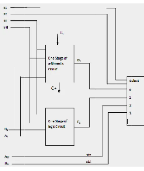
The number of micro operations implemented in an ALU affects the number of selections signals required. If we have 2m micro operations we will need m select inputs from control unit. The word size of the ALU must confirm to the word size of the digital circuit. Block diagram of an ALU is given in figure 1.2.
1.1.1 Ad-hoc Process
Ad hoc testing is a commonly used term for
F 1. The first is execu sequence Verilog ALU. modulealu input [3:0] input cin ; register output [6:0 output carr input [2:0] wire [7:0] assign resu assignalu assign carr function [7
Figure 1.2 One
2 Working
aim is to de uting 5 diffe
e is based o code is sho
(a,b,cin,alu,car a,b; // po ; // carry
0] alu; // th ry; // car ctl ; // fun result; // A
ult = alu_out(a, = result[6:0]; ry = result[7] ;
7:0] alu_out;
stage of 4-bit
and Descrip
esign a 4-bit erent operat on a contro own below
rry,ctl); ort A,B
y input from ca
he result rry output nctionality cont ALU result ,b,cin,ctl); ; ALU ption ALU which tions whose ol signal. A for module
arry flag
trol for ALU h e A e defau end endfu Figu A 3inp 3 bit inpu have II.0 beca 15. ult : begin
alu_ou d
endcase unction
ure 1.3 Verilog Addition with c
puts a, b, cin
t input and o ut and output e been shown
version 5.0. ause it suppor
ut=8'bxxxxxxx
g codes for Incr carry, Greater th
operations
n are 4 bits, c
utput alu is a waveforms fo n below usin Version 5.0 rts the CPLD
xx;
rement, Decrem han and less th
control input
a 7 bit output or these opera ng Altera Qu has been sel EPM7128SL
ment, han
LC84-IJISET - International Journal of Innovative Science, Engineering & Technology, Vol. 2 Issue 4, April 2015. www.ijiset.com
ISSN 2348 – 7968
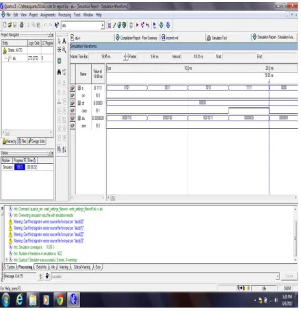
Figure 1.4 I/O waveform of ‘less than’ operation
Figure 1.5 Increment ‘a’ simulation result
Figure 1.6 Greater than operation simulation result
Figure 1.7Decrement ‘a’ simulation result
Figure 1.8 I/O waveform of Add with carry operation
The second step is now to implement a faulty ALU. We are introducing a fault in one function. We are introducing Stuck at Zero fault in Smaller than function. This means that when Smaller Than function is executed, whatever input is less, it will be generated at the output, but, since, we have stuck the output pin to zero, the Smaller Than function will not be executed. The input and output waveforms have been shown along with the faulty function.
Figure 1.10 I/O waveform of a faulty ALU system
Now the Ad-hoc process has to be implemented for making this ALU fault detection enabled, which means that the fault that we have introduced must be detected otherwise a false output will be executed. For this purpose we are
XORingthe ALU and faulty ALU. The
concept being that, the output of XOR is 0 if the inputs are same and 1 if the outputs are different. If ALU and Faulty ALU’s outputs will be same the output will be zero. But since, we have introduced a fault the output has to be 1. This is shown in the figure below. The RTL view for this circuit has been shown below.
Figure 1.11 ALU and Faulty ALU has been XORed to check for faulty output
The input and output waveforms for this circuit has been shown below. The
Figure 1.12 I/O waveforms showing a 1 at the output, which shows that there is a fault in the output.
This shows that our ALU can detect the fault present. The final process is to check the operation using CPLD.
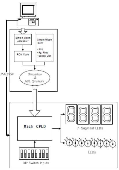
Figure 1.13 Overview of interfacing the Software with Hardware, i.e., downloading the module on
CPLD machine
IJISET - International Journal of Innovative Science, Engineering & Technology, Vol. 2 Issue 4, April 2015. www.ijiset.com
ISSN 2348 – 7968
Figure 1.13 Prototype board of CPLD EPM7128SLC84-15
The operation has been verified using CPLD also.
Figure 1.14Pin planner of CPLD EPM7128SLC84-15
Figure 1.15Daughter board of CPLD EPM7128SLC84-15
Figure 1.16I/P and O/P LEDs response of CPLD to a given ALU operation execution
1.3 Conclusion
testing, Scan methods can also be implemented.
1.5 References
[1] Ateeq A. Khan, “An Improved Design of
ALU Targeted to State-of-the-Art FPGAs”,
European Journal of Scientific Research ISSN 1450-216X Vol.63 No.3 (2011), pp. 456-463 © Euro Journals Publishing, Inc. 2011
[2] Samuel Winchenbach, Department of Electrical and Computer Engineering Mohammed Driss, Department of Electrical and Computer Engineering University of
Maine, Orono, “8-Bit Arithmetic Logic
Unit”, European Journal of Scientific
Research ISSN 1450-216X Vol.47 No.3 (2009), pp. 469-475 © Euro Journals Publishing, Inc. 2009
[3] Synthesis and Simulation Design Guide: A
copyright production of Xilinx, Inc.
[4] Jin-Young Kim, Sehoon Kim, Joonhee
Kang, “Construction of an RSFQ 4-bit ALU
with half adder cells”, Applied
Superconductivity,IEEE Transactions on June 2005,Volume: 15, Issue 2, Pages: 308 – 311, IEEE Spectrum
[5] Samir Palnitkar, “Verilog Hdl: A Guide to Digital Design and Synthesis”
[6]http://en.wikipedia.org/wiki/Ad_hoc_testi
ng
Abhishek Singh is currently working as an asst. professor in GGITS, Jabalpur. He did his B.E in 2009 in Electronics and Communication Engineering and M. Tech in 2012 in Embedded System and VLSI Design from the same institute. He has over 5 years
Communication Engineering and M. Tech in 2010 in Embedded System and VLSI Design from the same institute. He has over 5 years of teaching experience. His area of interest include Electronics, VLSI, Analog and Digital Communication.
Kalpita Agrawal is currently a final year student pursuing her Bachelor of Engineering in Electronics and Communication Engineering. Her area of interest include Electronics, VLSI, Optical Communication and Digital Electronics.