Transactions, SMiRT-25 Charlotte, NC, USA, August 4-9, 2019
Division V
STUDY ON MODELING OUT-OF-PLANE BEHAVIOR OF SC WALLS
USING SHELL ELEMENTS
Kadir C. Sener1, Amit H. Varma2
1 Post-Doctoral Researcher, Purdue University, West Lafayette, IN, USA ([email protected]) 2 Karl H. Kettelhut Professor, Purdue University, West Lafayette, IN, USA
ABSTRACT
The design of nuclear concrete structures for combined loading conditions including seismic event, accident thermal, external hazard etc. is a challenging task. Therefore, elastic finite element analysis of these structures is usually employed by the profession in industry. Though there are advantages and limitations to this approach, the advantages can be further enhanced by calibrating the method to results from nonlinear finite element analysis, which accounts for cracking due to thermal gradient, material nonlinearity, and other damaging phenomenon. However, the nonlinear finite element analysis needs to be verified against experimental data and measurements of the influence of accident thermal loading on the stiffness, strength, and deformation capacity of nuclear structures. The accuracy of finite element models is crucial for reasonably and conservatively calculating the design demand forces of the structure. This paper includes benchmarking of nonlinear finite element models using layered composite shell elements against large-scale steel-plate composite (SC) beam tests based on the observed behavior such as stiffness, strength, and deformation capacity.
INTRODUCTION
Benchmark numerical models of out-of-plane shear SC beam tests using layered composite shell (LCS) element models were performed using available test data found in the literature. LCS models were used in the investigations of SC walls subjected to accident thermal and mechanical loading. LCS models use nonlinear shell elements that are similar to conventional shell elements with the exception that they utilize layers (plies) to model the steel faceplates and the concrete infill sandwiched in between them. Interfacial elements (e.g. studs) or out-of-plane shear reinforcement (e.g. tie bars) cannot be incorporated into LCS elements. Strain compatibility is enforced between the layers of the shell element. Despite its limitations, the LCS elements are computationally efficient and practical for preliminary design and performance evaluation of nuclear structures consisting of SC walls.
are used. This stiffness improvement is expected to be more critical for regions that are shear critical, as the case for SC members having low shear span-to-depth ratio (a/d) or SC walls regions subjected to large out-of-plane shear-to-moment ratio (M/Vd).
MODELING APPROACH
The main objectives of this study are to (i) develop benchmark numerical models for out-of-plane shear tests of SC walls using LCS elements. (ii) evaluate linear analysis methods and validating against the results from nonlinear analysis and experimental data, and iii) provide correction factors to accurately capture the out-of-plane (transverse shear) stiffness for shell elements representing SC walls at ambient and elevated temperature conditions.
The models were developed and analyzed using Abaqus (Dassault, 2013) because of its capabilities with regards to modeling nonlinear behavior of materials (steel and concrete), and robust solution strategies including dynamic explicit analysis for predicting behavior with severe nonlinearities such as concrete cracking and steel yielding. The explicit dynamic analysis approach was used to perform the quasi-static analyses because of extensive concrete cracking. The system kinetic energy in the model was monitored continuously and maintained below 5% of the system internal energy.
Layered composite shell (LCS) elements were used to develop models to investigate SC walls subjected to: (i) accident thermal loading, followed by (ii) mechanical loading. LCS elements utilize layers to model the steel faceplates and the concrete infill regions. Strain compatibility enforced between shell layers prevent any slip to be defined between layers. Steel web (inner) plates, shear studs and tie bars cannot be modeled using LCS elements. Thus, steel plate local buckling, interfacial slip between the steel faceplates and concrete infill, and out-of-plane (transverse) shear failure are not possible when using LCS elements. Regardless of these limitations the LCS elements are computationally very economical when compared against models developed using solid element for each structural member in the SC wall system. LCS models are particularly useful to account for the influence of concrete cracking on lateral stiffness, and provide conservative estimations for the lateral load capacity of structures.
The nonlinear shell elements used in the models were the 4-node (S4R) shell elements with reduced integration. The thickness of each layer or ply in the shell element is specified in the section properties based the particular geometry of each layer of the particualr SC wall. The S4R element has only one-integration point across its length and width, but it can have several one-integration points through the thickness in each layer. In this study, three layers (steel-concrete-steel) and a total of 23 integration points through the SC wall thickness were used, which included three integration points in each faceplate layers and 17 integration points for the concrete layer. A uniform finite element mesh size was used in all the models by setting the typical size equal to 2 inches.
Concrete Material Model
Concrete damaged plasticity (CDP) model available in Abaqus/Explicit were used for the analysis. These models explicitly account for concrete tension behavior using smeared cracking combined with fracture energy principles. Concrete damaged plasticity (CDP) material model incorporates assumes isotropic damage behavior in tension. This feature results in material point to degrade isotropically in all three orthogonal directions after cracking in any one direction.
Steel Material Model
(S4R). This S4R element is a linear, finite-membrane-strain, quadrilateral shell element that is suitable for both thick and thin plate type problems. The formulation is based on thick shell theory, but it converges to Kirchoff’s thin plate bending theory with reducing thickness. The steel material is modeled using multiaxial plasticity theory with von-Mises yield surface, associated flow rule, and isotropic hardening.
Thermal Material Properties of Steel and Concrete
Nonlinear heat transfer analysis was conducted to simulate the effects of accident thermal loading, and to calculate the nodal temperature histories and temperature profiles through the thickness of the composite SC walls in the idealized modular structure. The thermal material properties (conductivity and specific heat) used in the heat transfer analyses were taken from the publication by Hong and Varma (2009).
FINITE ELEMENT ANALYSES OF SC BEAM TESTS USING SHELL ELEMENTS
Analysis of SC shear wall and wall panel tests using finite element method were conducted previously by the authors and were presented in detail Sener et al. (2019). Benchmark analysis of unreinforced SC beam specimens using solid elements were performed and presented in Sener et al. (2016). Implementation of these solid models for practical purposes would not possible as they are computationally very expensive due to the need for detailed modeling of each structural member (studs, tie bars, inner-diaphragm plates) individually. Therefore, modeling of large structures are typically performed using linear or nonlinear shell elements. The usage of nonlinear shell elements have been demonstrated by modeling several large scale SC structures by the authors (Sener et al. 2014 and Booth et al. 2015). These studies have demonstrated that nonlinear composite shell models can predict the lateral load capacity, stiffness and deformation capacity with a reasonable accuracy. The lateral load capacity and behavior of these modelled structures were typically governed by in-plane shear behavior since the lateral load was mainly resisted by walls parallel to the loading direction and located near the core (central) region of the structure. Out-of-plane shear failure is not expected to occur in these structures when subjected to lateral loading. However, accurate modeling of out-of-plane shear stiffness is important for obtaining reasonable global structural stiffness estimates. Out-of-plane shear demands become critical for designing safety-related nuclear structures for load cases including; (i) internal pressure due to accident conditions, (ii) external pressure due to wind or external hazards, (iii) temperature differences between interior and exterior of structural walls due to accident conditions. Out-of-plane shear and moments are maximized near the discontinuity regions such as large openings or connection regions near the basemat.
Accurate prediction of out-of-plane shear stiffness is also important when performing linear elastic shell analysis of large structures. These analyses are performed to obtain force and moment demands to design the structure against. Inaccurate estimation of the structure stiffness may result in structure designs either overly conservative or unsafe structures. Minimizing the stiffness inaccuracy that would stem from out-of-plane shear stiffness estimations becomes critical for analysis and design of structures. Thus, this study investigates the transverse shear stiffness parameter that would reasonably capture the stiffness of experimental data from beam tests.
This study focuses on the analysis of shear-reinforced beam specimens tested by the authors using FE method to investigate the applicability of the LCS elements on the out-of-plane shear and flexural behavior. The authors conducted eight large-scale beam tests of specimens having shear reinforcement. These specimens also had shear studs to anchor the steel faceplates to the concrete infill. The shear reinforced specimens were named as SP2 specimens, and three different shear reinforcement types were used for the specimens. The shear critical specimens were the; (i) three Series 2a specimens (1, SP2a-2, and SP2a-3) having deformed rebars for shear reinforcement., (ii) one Series 2b specimen (SP2b-1) having channel sections for shear reinforcement, and (iii) four Series 2c specimens (1 through SP2c-4) having rectangular steel plates for shear reinforcement. All the specimens were tested in four-point bending loading configuration with shear span-to-depth ratios ranging from 2.5 to 5.5. Additional geometric and material property details of the tested specimens are provided in the reference papers.
The models developed using LCS elements based on the measured geometric and material properties of infill concrete and steel faceplates. Shell elements in Abaqus are based on first-order transverse shear flexible theory; therefore, the transverse shear strain is assumed to be constant through the thickness of the shell and requires the usage of shear correction factors for accurate estimation. The default transverse shear stiffness is calculated only once using a parabolic variation of transverse shear stress in each layer. FE software packages calculate the transverse shear stress are based on initial elastic material definitions using the input material properties data. Thus, the transverse shear stress calculations are performed only once and in the beginning of the analysis without any updating during the analysis. Any change in the transverse shear stiffness that may occur due to changes in the material stiffness, such as cracking in concrete or steel yielding are not accounted during the progression of the analysis. This results in the default transverse shear stiffness calculation for shell elements to overestimate the transverse shear stiffness of concrete members since reduction in the transverse stiffness is ignored. Abaqus allows direct specification of transverse shear stiffness (Kts
11, Kts22, Kts12) terms to partially rectify this issue.
Since SC walls are comprised of thin steel faceplates on the exterior surfaces, the thick infill concrete in the middle portion resists the majority of the out-of-plane shear demand. Therefore, it is plausible to specify the member transverse shear stiffness based only on the concrete infill contribution. The shear stiffness calculations include a correction coefficient (shear factor) to account for the fact that the shear stress and shear strain are not uniformly distributed over the cross section. The shear factor is used to correct the ratio of the average shear strain of a section to the shear strain at the centroid, as the transverse shear strain is assumed uniform. This factor is shown to be equal to 5/6 for rectangular sections as shown by Cowper (1966).
The first approach proposed for calculating transverse shear stiffness is shown in Equation 1. This approach assumes that the out-of-plane shear response is governed by the un-cracked concrete section remaining after initial flexural cracking. Therefore, G13 is taken as the concrete shear moduli. The reduction
in the SC section shear stiffness due to concrete cracking is accounted in the calculations with a similar approach as the flexural stiffness calculations. Cracked-transformed flexural stiffness is calculated according to Equation 2. The equation accounts for concrete flexural stiffness reduction from the un-cracked case (EcIc) with a coefficient c2. This coefficient is used for determining the uncracked portion of
SC section to be accounted in the effective transverse shear stiffness of SC sections. The neutral axis location or depth of concrete in compression (c) is calculated from the effective reduction factor (c2EcIc).
Out-of-plane (transverse) shear stiffness is then computed by using the calculated depth of concrete in compression (c) to be resisting the shear demands in the cross-section. Concrete shear modulus is taken approximately as 40% of Young’s modulus of concrete (Ec) in the calculations.
𝐾
11𝑡𝑠= 𝐾
22𝑡𝑠=
56
(𝐺
13𝑐), 𝐾
12𝑡𝑠
= 0, 𝑤
ℎ
𝑒𝑟𝑒𝐺
𝑐
2= 0.48𝜌
′+ 0.10, 𝑤
ℎ
𝑒𝑟𝑒 𝜌
′=
2𝑡𝑝𝑇 𝐸𝑠
𝐸𝑐 (2)
A second approach is proposed as a lower-bound estimation of the transverse shear stiffness for members. This approach is developed for cases where neutral axis location is very small or lies outside the cross-section; for example, members subjected to concurrent axial tension or accident thermal loading cases which cause thru-depth concrete cracks. The lower-bound transverse shear stiffness is developed using the truss analogy for the transfer of internal force distribution of a concrete member. The truss mechanism forms by the equilibrium at nodal zones that compression struts and tension ties join. The vertical displacement (δ) of the idealized truss beam is calculated using the stiffness of the compression struts and assuming infinite stiffness for the ties. This calculated vertical displacement is approximated to shear strain by dividing by the shear span (θ=δ/a). The simplified numerical formula for the minimum transverse shear stiffness is obtained as shown in Equation 3.
𝐺𝐴
𝑚𝑖𝑛= 0.10𝐸
𝑐𝑡
𝑠𝑐 (3)FE Analysis of SP2a Specimens
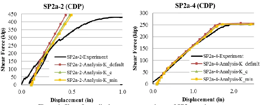
SP2a series specimens had round deformed bars for shear reinforcement. The specimens had identical cross sections with section depth (TSC) of 36 in, bw/d ratio of 0.94, tp of 0.75 in, ρ of 4.2%, and s/tp ratio of 11.3. The shear span-to-depth (aspect) ratios of Specimens SP2a were; 3.5 for SP2a-1, 2.5 for SP2a-2, and 5.5 for SP2a-4. Figure 1 presents representative comparisons of numerically predicted and experimentally measured shear force versus mid-span displacement responses for select SP2a series specimens. The figures indicate that the prediction from the LCS model for the specimen having large aspect ratio is improved compared to the specimen with short aspect ratio. The utilization of reduced transverse shear stiffness approaches resulted in improved comparisons with the experimental responses and this contribution was more significant for the smaller aspect ratio case. The LCS analysis results overestimated the strength of the shear controlled specimens (SP2a-1 and SP2a-2), due to the limitation of capturing transverse shear failure. However, the LCS models accurately captured the flexural response for the specimen which the strength was controlled by flexural yielding of the steel faceplates (SP2a-4).
Figure 1. Shear force-displacement comparisons of SP2a specimens
FE Analysis of SP2b Specimens
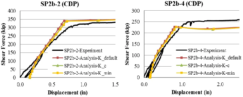
representative comparisons of numerically predicted and experimentally measured shear force versus mid-span displacement curves for the SP2b series specimens. The figures indicate that the analysis results reasonably predict the load-displacement response of the specimens. The utilization of reduced transverse shear stiffness resulted in improved comparisons with the experimental responses. Analysis performed using the LCS models captured the governing failure mode for most of these specimens due to the observed flexural yielding of the steel faceplates. These specimens experienced additional deflection due to partial composite action, which can be captured only by solid element models incorporating connector elements to model the interfacial slip between the faceplates and concrete infill. The LCS elements overestimate the beam stiffness, since these elements cannot incorporate slip between layers which would further reduce the global beam stiffness.
Figure 2. Shear force-displacement comparisons of SP2b specimens
FE Analysis of SP2c Specimens
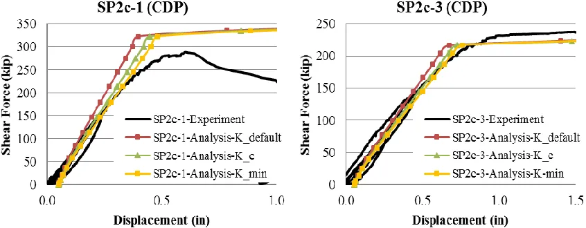
SP2c series beam specimens with rectangular plates for shear reinforcement had the following geometries. Specimens SP2c-1 and SP2c-3 had identical cross sections with section depth (d) of 30 in, bw/d ratio of 0.5, tp of 0.75 in, ρ of 5.0%, and s/tp ratio of 6.7, but had different shear span-to-depth ratios of 2.0 and 3.0, respectively.
Figure 3. Shear force-displacement comparisons of SP2c specimens
FE Analysis of SP3c Specimens
This study also included analysis of specimens tested by the authors that were subjected to combined thermal and mechanical loading. The objective of these tests was to investigate the influence of thermal loading on the out-of-plane shear and flexural response of SC walls (Sener et al. 2014, derek). The experimental program included beam tests similar to the previously tested specimens with the addition of thermal loading in one of the shear or mid-span of the specimens. The experimental study indicated that thermal loads reduce the out-of-plane shear strength and flexural stiffness of SC walls. Two beam tests of SC walls subjected to combinations of mechanical and thermal loads were modeled using nonlinear shell elements and the effects on the transverse shear stiffness parameter were studied.
The tested specimens, SP3c-1 and SP3c-2, had similar design as the SP2c series beam specimens with rectangular plates for shear reinforcement. Specimen SP3c-1 was a larger specimen with section depth (d) of 48 in, bw/d ratio of 0.5, tp of 0. 5 in, ρ of 2.08%, and s/tp ratio of 16.0. Specimen SP3c2 had a cross section with section depth (d) of 30 in, bw/d ratio of 0.5, tp of 0.75 in, ρ of 5.0%, and s/tp ratio of 6.7, and had shear span-to-depth ratio of 2.0. SP3c-1 was heated in the uniform moment region (mid-span) to confirm the effects of accident thermal loading on flexural capacity. Specimen SP3c-2 was heated in one of the uniform shear regions to confirm the effects of accident thermal loading on out-of-plane shear strength.
Figure 4. Shear force-displacement comparisons of SP3c specimens
Summary of Analysis of SC Beam Specimens
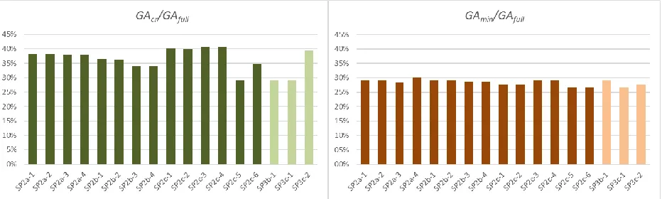
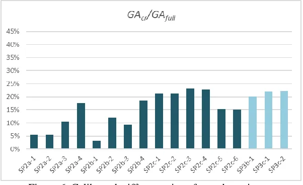
The two approaches used to calculate transverse shear stiffness are normalized with shear stiffness contribution of uncracked SC section in Figure 5. A final calibration approach has been implemented to evaluate the effective transverse shear stiffness of the tested specimens based on the test data. The last approach calibrated the transverse shear stiffness parameter of the LCS model based on the load-displacement responses obtained at 60% of corresponding specimen’s load capacity. The ratio of the calibrated stiffness values to the corresponding specimen’s full (un-cracked) SC section shear stiffness is shown in Figure 6.
Figure 5. Stiffness ratios of tested specimens using the first and second approach
Figure 6. Calibrated stiffness ratios of tested specimens
NUMERICAL PARAMETRIC STUDY
A parametric study of an idealized SC beam was conducted to investigate the sensitivity of transverse shear stiffness on different shear span-to-depth ratios. The parametric study was performed on a SC beam with varying shear span-to-depth ratio (a/d) in the range of 1.5 to 10.5. The beam section was selected to be identical to Sp2a specimens with 36-in. section depth and 0.75 in thick steel faceplates. Nominal material properties were used for steel and concrete. The steel faceplate yield strength was 50 ksi, used with an idealized steel stress-strain relationship. The compression strength of concrete infill was 4 ksi with an idealized concrete stress-strain relationship. The parametric study included four different transverse shear stiffness levels by having 100%, 50%, 25% and 10% of the un-cracked shear stiffness of concrete and measuring the displacement under the load point. The transverse shear stiffness for the case of un-cracked (100%) transverse shear stiffness is illustrated in Equation 4, per unit width. The stiffness cases were calculated by taking ratios of the calculated un-cracked transverse shear stiffness calculated shown below.
𝐾
100%𝑡𝑠=
56
(0.4𝐸
𝑐𝑡
𝑐) =
56
(0.4 ⋅ 3605𝑘𝑠𝑖 ⋅ 34.5𝑖𝑛) = 41457
𝑘𝑖𝑝𝑖𝑛 (4)
Figure 7. Shear force-displacement comparisons of SP2b specimens
load-point displacement is observed for the case of 10% stiffness case. This load-load-point displacement is mitigated with increasing stiffness levels, but still considerably large to be accounted in the analysis. This study has shown the significance of accounting for transverse shear stiffness in the models, considering that the transverse shear stiffness obtained from the LCS model using the experimental database is about 20%. The parametric study verified that the influence of transverse shear stiffness is not negligible and should be accounted in shell models to obtain accurate results.
CONCLUSION
This paper presented the benchmarking analysis of out-of-plane shear SC beam tests that are found in the literature that are subjected to mechanical and thermal loading. The experimental results and behavioral observations were overestimated when default transverse shear properties were used in the models. The analysis results were significantly improved when reduced transverse shear stiffness was used due to concrete cracking. Two approaches were proposed to estimate transverse shear stiffness of SC walls. The proposed methods were compared well with the calibrated values for wide range of specimens that were in the database. The paper also presented a parametric study using an idealized SC beam to study the additional shear deformation that stem from reduced transverse shear stiffness. The study indicated that the shear deformation is maximized for low shear span-to-depth ratio levels and low transverse shear stiffness contributions. This additional deformation diminished with for larger transverse shear stiffness levels, however it is recommended to take account of the transverse shear stiffness parameter for shell elements based on the two approaches presented in this study.
REFERENCES
Booth, P.N., Varma, A.H., Sener, K.C., and Malushte, S.R., (2015). Flexural Behavior and Design of Steel-Plate Composite (SC) Walls for Accident Thermal Loading. Nuclear Engineering and Design, Special Issue on SMiRT-22 Conference, Vol. 295, pp. 817-828, Elsevier Science. http://dx.doi.org/ 10.1016/j.nucengdes.2015.07.036
Cowper GR., (1966). “The shear coefficient in Timoshenko’s beam theory”, Journal of Applied Mechanics 33(2), 335-340
Hong, S., Varma, A.H., (2009). Analytical modeling of the standard fire behavior of loaded CFT
columns. Journal of Constructional Steel Research, Vol. 65, Elsevier. pp 54-69.
Sener KC, Varma AH., (2014). “Steel-plate composite walls: Experimental database and design for out-of-plane shear.” Journal of Constructional Steel Research; Volume 100, pp. 197–210