Transformer Fault Detection Using
Frequency Response Analysis
Seema Arora
1, Bhavna Srivastava
2, Priyanka
3, Raghav Parashar
4, Shivangi Gaur
51Faculty of Electrical and Electronics Engineering Department, Galgotias College of Engineering and
Technology, Greater Noida
2,3,4,5 Students of VII Sem, B.Tech, Electrical And Electronics Engineering Department, Galgotias College of
Engineering and Technology, Greater Noida
ABSTRACT: Power transformers prove to be a vital element or tool in electrical power supply and transmission system. They are capital intensive units and need to be monitored for faults. Faults in transformers leading to their failure are repugnant. Thus, there is a need to detect such faults at an initial level. This paper aims to detect, diagnose the nature and cause of mechanical faults, their identity, type and their locale using frequency response analysis.
KEYWORDS: Mechanical faults, transfer function, frequency signatures, frequency response analysis, mechanical deformations, inter turn short circuits.
I. INTRODUCTION
M
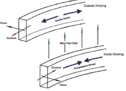
ECHANICAL faults in transformers can pose a great threat to electric power system. There are many conditions when transformers can fail mechanically. Inter-turn short circuit, axial displacement of windings, forced buckling, disk to ground faults, leakage faults, axial bending are some of such catastrophic events. Short circuit events [Fig.1] in transformer windings generate strong electromagnetic forces, namely, radial and axial forces [Fig. 2]. These forces may cause buckling of conductors, winding displacements, stretching of conductors, which further lead to failure of transformers. Hence, monitoring health of transformers regularly becomes indispensable for uninterrupted and cost effective operation of power systems.Frequency Response Analysis (FRA) is a trenchant tool for monitoring transformers. Frequency response analysis is a potent method to diagnose mechanical faults at an initial level, thereby, preventing transformer from complete breakdown. This technique uses the frequency range of 20 Hz – 2 MHz for analyzing the response curve of transformers for detail inspection of faults.
However, a main disadvantage of frequency response analysis technique is that deduction of transient response from knowledge of frequency response is not always easy. FRA is an omnipotent technique that visualizes the transfer function of transformers to inspect their mechanical health by analyzing their cores and windings. The whole technique of FRA is based on comparisons which are typically taken in three manners:
1. Time based comparison: Current condition is compared with previous condition of same transformer. 2. Type based comparison: Conditions of two equal transformers are compared.
Fig. 1: Typical short circuit fault characteristics
This paper presents a novel approach to quantify certain signature parameters. Study of incipient transformer faults and mechanical deformation on the basis of simulation of continuous parameter model of transformer is being done. The authors are to present and quantify Faults in their future work.
In section II, literature review has been discussed and section III, deals with transfer function approach on the basis of continuous parameter model of the transformer. In section IV, numerical simulation of transfer function has been covered with the results. Section V presents the conclusion of our work.
Fig. 2. Electromechanical stresses developed in transformer windings
II. LITERATURE REVIEW
Simulation model of a 132/11 KV, 30 MVA transformer was developed to generate frequency response signature and then its sensitivity towards axial displacement, axial bending and forced buckling was analyzed [3]. In work carried by P.M. Joshi and S.V. Kulkarni [4], deformations in transformer windings were premeditated on the basis of terminal capacitance measurement. A term called “Deformation Coefficient” was coined here which is defined as the function of ratio of change in capacitance at one end to the other. This technique even facilitated the determination of the extent and location of deformation.
Another approach delineated by Mrs Pradnya R Jadhav and Dr. P.M.Joshi [1] considered the equivalent circuit of transformer winding using state space model. It assisted in studying the mechanical probity of a transformer after short circuit fault, transportation, etc. M.R.Barzegaran and M.Mirzaie focused on the inspection of position of internal short circuit in transformers utilizing the high frequency model of transformer winding [5].
different transfer functions, the resonant frequencies differ and were highly dependent on mechanical displacements.
III.TRANSFER FUNCTION APPROACH
Transfer function is defined as the ratio of output function to input function. In transformer, transfer function signifies ratio of current and voltage on transformer terminals.
Let Iin, input current and
Uin,supply voltage be the input quantities of the transformer unit which are functions of frequency. Let Ion, output current and
Uon, output voltage be the output quantities of the transformer unit which are functions of frequency. Now, transfer function of transformer as per above given definition can be expressed as:
1. Current transfer function :
TF1(f) = Ion(f) / Iin(f) (1) 2. Voltage transfer function :
TF2(f)= Uon(f) / Uin(f) (2)
3. With current and voltage of input terminals referred : TF3(f) = Iin(f) / Uin(f) (3)
These equations illustrate the dependency of transfer function over frequency domain. Mechanical faults in transformer windings bring a change either in their shape or in the dielectric properties of insulation system. These changes further lead to changes in internal capacitance, conductance and resistance of windings, thus, causing a change in impedance or admittance of windings.
The impedance or admittance is functions of frequency and any change in these parameters signify a variation in frequency of system. Transfer function of a system (in this case transformer) being dependent on frequency varies from its healthy signature and this variation detects occurrence of faults in transformers.
Transfer functions of healthy and faulty situations of transformer are compared to detect faults. The alikeness between the two decides about occurrence of faults and their intensity. There are different ways to explore this alikeness. Some of them are:
1. Coherence/difference function:
Y2AB(f) = |GAB(f)|2 / GAA(f).GBB(f) (4)
The analogy of two functions at a given frequency f is provided by this function.
For a healthy transformer, Y2AB(f) = 1
1. But, the coherence function deviates from its signature value when fault arises.
2. Total deviation of transfer function is given by:
S(fx)= ∑(1- Y2AB(k)) (5)
For k=f0...fx
This relation is obtained by scaling coherence function from 0 to full scale and then adding them.
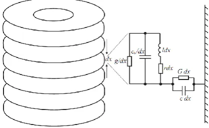
Consider the continuous parameter model of a transformer [Fig.3].
Fig. 3 Continuous parameter model of transformer
For dx length of winding if,
g/dx = inter turn conductance per unit length, cs/dx = inter turn capacitance per unit length, l dx = self inductance of given length, r dx = resistance of given length,
G dx = ground conductance of given length, C dx = ground capacitance of given length, Un = voltage of n
th
winding. Now, current in nth winding is,
icn = c∆x ∂un / ∂t + un ∆x. G (6) Current in nth winding is also coming from (n-1) th winding,
i`sn = cs∆x ∂(un-un-1) / ∂t + (un-un-1) ∆x.g
= cs∆x ∂∆`un / ∂t + ∆`un∆x.g (7) Current going to (n+1)th winding
i``sn = cs∆x∂(un-un+1) / ∂t + (un-un+1) ∆x.g
= -cs∆x ∂ ∆``un / ∂t - ∆``un∆x.g (8) Since,
isn = i`sn + i``sn Hence,
isn=-cs∆x ∂∆2u / ∂t - ∆2u. ∆x.g (9) Taking assumption that ∆x=a and then calculating current from the equation:
-∆in = icn + isn
Solving equations we get,
∂i/∂x= -c ∂u/∂t– uG +csa2 ∂3a /∂t. ∂x2+ga2 ∂2u / ∂x2 (10) We know,
Z = sl+r Y = sC+G Ys = scs+g
where, Z,Y,YS are in laplace form. Now,
L[∂u/∂x] = ∂U(s,x) / ∂x = -Z.I(s,x) (11) L[∂i/∂x] = ∂I(s,x) / ∂x = -Y.U(s,x) + Ysa2 ∂2U(s,x) / ∂x2 (12)
On working further, we get, ∂2U(s,x) / ∂x2 –( Z.Y / (1+Z.Y
sa2)). U(s,x) = 0 (13) ∂2I(s,x) / ∂x2 –( Z.Y / (1+Z.Y
sa2)). I(s,x) = 0 (14)
U(s,x) = A1e-αx + A2e αx (15) I(s,x) = (A1e- αx – A2e αx) / Z0 (16) where,
α = (ZY/(1+ZYS.a2))1/2 Z0 = ((1+ZYS.a2)Z /Y)1/2
We know, transfer function is,
H(s) = Uout(ω) / Uinp(ω) = U(s,d) / Uinp(s)
where, d: total length of winding.
Hence,
H(s) = Zout / [Zinp.{(1+ Zout.Yinp).cosh(αd) + (Yinp.Z0 + Zout / Z0).sinh(αd)}] (17)
When the above parameter model is simulated through MATLAB, voltage signature of healthy transformer was observed as shown in Fig. 4.
Fig. 4: Voltage signature of healthy transformer
V. CONCLUSION
Each electrical network has its exclusive frequency response, called „fingerprint‟. Faults and mechanical deformations cause variation in this fingerprint. Comparison of original fingerprint of transformer with previous measurements done on the same transformer gives count of the positional/electrical deviations in them. Visual examination of curves or processed FRA data gives required results.
This paper discusses the method of numerical simulation of a continuous parameter model of transformer with the frequency signature of healthy transformer. This frequency signature is obtained by formulating Matlab code for the described numerical simulations, given in the paper. We intend to compare this signature of a transformer with signature obtained during fault condition and compare the results.
REFERENCES
[1]. Pradnya R.Jadhav and P.M. Joshi: Study of Transformer Winding Parameters as Deformation Diagnostics Techniques Using FRA Measurement
[2]. Ebrahim Rahimpour, Jochen Christian, Kurt Feser, Fellow, IEEE, and Hossein Mohseni: Displacement and Radial Deformation of Transformer Windings (IEEE TRANSACTIONS ON POWER DELIVERY, VOL. 18, NO. 2, APRIL 2003)
[3]. J.A.S.B. Jayasinghe, Z.D. Wang, P.N. Jarman and A.W. Darwin: Winding Movement in Power Transformers: A Comparison of FRA Measurement Connection Methods (2006 IEEE)
[4]. P. M. Joshi and S. V. Kulkarni, Member, IEEE: Transformer Winding Diagnostics Using Deformation Coefficient (2008 IEEE)
[5]. M.R.Barzegaran and M.Mirzaie: Detecting the Position of Winding Short Circuit Faults in Transformer Using High Frequency Analysis (European Journal of Scientific Research; 2008)
[6]. J. Chong and A. Abu-Siada, Member, IEEE: A Novel Algorithm to detect Internal Transformer Faults (2011 IEEE)
ACKNOWLEDGEMENT