A Study on the Local Impact Behavior of SC Walls
Using Actual Test and Simulation
Kapsun Kim1, Yongpyo Suh2, Ilhwan Moon3, and Hyungjin Choi4
1
Senior Researcher, Korea Hydro & Nuclear Power Co., LTD Central Research Institute, South Korea 2
Project Manager, Korea Hydro & Nuclear Power Co., LTD Central Research Institute, South Korea 3
General Manager, KEPCO Engineering & Construction Company, Inc., South Korea 4
Executive Director, Karagozian & Case, USA
ABSTRACT
International regulations for nuclear power plants strictly prescribe the design requirements for local impact loads, such as aircraft engine impact, and internal and external missile impact. However, the local impact characteristics of Steel-Plate Concrete (SC) walls are not easy to evaluate precisely because the dynamic impact behavior of SC walls which include external steel plate, internal concrete, tie-bars, and studs, is so complex.
In this study, dynamic impact characteristics of SC walls subjected to local missile impact load are investigated via actual high-speed impact test and numerical simulation. Three velocity checkout tests and four SC wall tests were performed at the Energetic Materials Research and Testing Center (EMRTC) site in the USA. Initial and residual velocity of the missile, strain and acceleration of the back plate, local failure mode (penetration, bulging, splitting and perforation) and deformation size, etc. were measured to study the local behaviour of the specimen using high speed cameras and various other instrumentation devices. In addition, a more advanced and applicable numerical simulation method using the finite element (FE) method is proposed and verified by the experimental results.
Finally, the experimental results are compared with the local failure evaluation formula for SC walls recently proposed, and future research directions for the development of a refined design method for SC walls were reviewed.
INTRODUCTION
According to the International and Korean regulations for nuclear power plants, a nuclear power plant must be able to withstand local impact loads, such as aircraft engine impact, and internal and external missile impact.
These days, SC structure is widely used internationally for nuclear power plant design because of its efficiency of fabrication, erection, and construction. Although extensive studies on the local impact behavior of the conventional RC (reinforced concrete) wall have been performed, and the design methodologies to prevent local failure are already established and included in NEI 07-13 (NEI, 2011) and DOE-STD-3014 (DOE, 2006), there is no such design methodology available for SC walls except for the one recently suggested by J.C. Bruhl et al. (Bruhl, J. C., 2015).
often very expensive. Therefore, they can be performed only in limited cases and only as a supplementary method.
In this study, a series of actual high-speed impact tests are performed to confirm the local impact behavior of SC walls and verify the proposed numerical simulation method. In addition, an improved numerical simulation technique using the FE method via the commercial FE code LS-DYNA is introduced, and the detailed local impact characteristics of SC walls subjected to local missile impact load are investigated using the suggested numerical simulation method. Finally, the results are compared with the design methodology for SC walls recently proposed, and future research directions for the development of a refined design method for SC walls were reviewed.
ACTUAL IMPACT TEST
Test Aim
The objectives of the actual impact test are to confirm the dynamic impact characteristics of SC wall models and to verify the proposed numerical simulation method used in the analyses. These objectives are achieved by comparing the numerical and physical test results. Total four SC wall models with four sets of projectile are used in impact tests. The initial impact velocity is designed as 150m/s for all cases.
Projectile Design
The selection of a suitable scale for the testing program is critically important and must consider both the relevance and validity of the test results as well as practicability and cost-effectiveness. The existing testing facilities (gas-gun) in the EMRTC cater for projectiles of up to approx. 6” diameter, with reference to Table 1, this result in a test scale of around 1/10.
Table 1. Scaling of the Engine Simulant
Test Scale Engine Simulant Dimensions
Diameter(mm) Length(mm)
Full Scale 1400 2130
Tenth Scale 140 213
The proposed solution is to consider the effectiveness of the penetrator in terms of Kinetic Areal Density (the magnitude of kinetic energy imparted by the projectile, per unit area). This approach will consider the engine simulant as a comparable penetrator and model its penetration capacity or effectiveness. A comparison of Kinetic Areal Density for the full-scale engine impact and the test article is shown in the Figure 1, and the projectile design is shown in the Figure 2. Projectile diameter will be 150mm with an overall length of 300mm. The front end of the projectile will have a slight ogive, but will be aerodynamically unstable. The weight of the projectile and sabot parts will be approximately 40kgf.
Specimen Design
A several preliminary analyses are carried out using commercial FE program LS-DYNA in order to determine the design data for test panel. The SC panels which consist of the concrete having 150 ~ 250 mm thickness and steel plate having 4 mm and 6 mm thickness are considered. In addition, the projectiles having 150 m/s and 180 m/s velocity are used in the preliminary analysis. Based on the results of preliminary analysis, the four types SC panels are set to the final test panels. Table 2 shows test conditions and the design parameters of the final test panel. The expected failure modes corresponding to the design parameters are also described in the table. The detailed designs of the final test panel are shown in Figure 3. The SC panel specimens consist of external steel plate, internal concrete, and studs. Basically, this SC panel model has the same design as a real SC wall of the nuclear power plant, except for the absence of tie-bars and H-beam ribs. The overall size of the SC wall model is 2,000 mm x 2,000mm, and the thickness of the wall is 175mm and 250 mm, and the thickness of the steel plate is 4mm and 6mm.
Table 2. Specimen Design and Test Condition
Figure 3. Configuration of the SC Panel Specimen
No Specimen
Name
Wall Size (mm)
Wall thickness (mm)
PL. thickness (mm)
Design Velocity (m/s)
Expected Failure mode
1 SC175-4T 2000X2000 175 4 150 Perforation
2 SC250-4T 2000X2000 250 4 150 Penetration
3 SC175-6T 2000X2000 175 6 180 Perforation
4 SC250-6T 2000X2000 250 6 180 Bulging
Test Facility and Instrumentation
All tests were conducted using the EMRTC custom 6.4 inch smooth bore gas-gun. The gun tube was mounted on an M174 sled mount. M30 propellant with a 073 web size was used as the main charge. The charge weight was need to be dialed in to achieve a projectile velocity of 150 m/s. Velocity checkout tests were conducted prior to testing of customers penetrators in order to ensure a velocity of 150 m/s.
Figure 4 illustrates the location of the instrumentation and the overall views of the test setup. Five Strain gauges and two accelerometers were applied to the back of all SC panel targets before testing starts, and two high speed cameras were used to record the penetrator both before and after entering the concrete target. In addition, 8 foot long zebra boards were positioned behind the target to record velocity.
Figure 4. Instrumentation and Test Setup
OUTLINE OF NUMERICAL ANALYSIS
Numerical Analysis Method
Numerous alternative methods are available for the SC panel’s local impact analysis, ranging from the quasi-static methods that use a static implicit FE code to the detailed dynamic analyses that use a nonlinear explicit FE code. In this study, the dynamic impact characteristics of the model are investigated using an explicit nonlinear dynamic FE simulation with a three-dimensional detailed model of the complete SC panel via the commercial FE code LS-DYNA.
Modeling Detail
The analysis model represents the complete SC-panel and support structure, and all of the components are explicitly modeled in three dimensions. For computational efficiency, all of the FE models were modeled
(a) Strain gauge (c) High-speed camera
as a half symmetric model with symmetric boundary condition. A basic half-model consists of 393,569 nodes and 406,771 elements. 3D solid elements were used to model the concrete and projectile, and shell elements were used steel plate and support structure, and the shear studs were modeled with beam elements. Regardless of weld type, all welded connections are modeled using a continuous mesh across the weld, that is, as continuous full penetration butt welds. Figure 2 provides an overview of the FE model and mesh details. The mesh size is chosen to be appropriate for simulating the expected behavior of the SC panel based on comprehensive sensitivity analysis using various different mesh sizes.
Fixed boundary conditions were used for the support structure. At the start of each analysis, the projectile is located close to the SC panel target and given an initial impact velocity perpendicular to the target. All the interactions among the contact components are also modeled carefully using appropriate contact algorithms. The nodes of the shear studs are coupled to the nodes of the concrete through using *CONSTRAINED_ LAGRANGE_IN_SOLID in LS-DYNA.
Figure 5. Overview of the FE Model: (a) Projectile, (b) Specimen, (c) Whole model (half model x 2)
Material Model
The constitutive model used to model the concrete is Winfrith concrete model (MAT_084/085) which has been developed over the last two decades and validated against various impact and blast tests. This is premised upon a smeared crack, with a constitutive model capable of cracking and crushing and shear retention depending on crack width and aggregate size. The constitutive material model used to model the all of the steel component is *MAT_PIECEWISE_ LINEAR_PLASTICITY in LS-DYNA. This is a bi-linear elastic-plastic model that contains formulations of combining isotropic and kinematic hardening plasticity behavior with option of including strain rate effects and erosion criteria. In this model, strain rate effect is accounted for using the Cowper and Symonds model which scales the yield stress by the strain rate dependent factor. The mechanical properties of the SC panel used in manufacturing the test model are used in the FE model so that the FE analysis results can be compared on an equal footing with the test results.
(a)
ACTUAL TEST AND SIMULATION RESULTS
SC175-4T
Figure 6 shows the actual impact test situation of the test site. The impact test for SC175-4T (Type 1) is the test for the SC panel which has SC wall thickness of 175 mm and steel plate thickness of 4 mm. The designed missile speed for this SC panel is 150 m/sec and the anticipated failure mode is perforation.
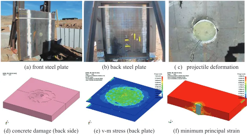
Figure 7 shows the actual test and numerical simulation results of the SC panel (Type 1). The measured impact velocity of the projectile was 147.5 m/s and the failure mode was perforation just like the expectation. The steel plate of the front side was clearly cut and the back plate was also torn completely as shown in Figure 7. Damaged area of the back plate was bigger than the front plate because of the conical plug occurrence of the concrete in the SC panel. In addition, most of the studs near the impact area were failed and the concrete of the impact area was crushed completely. The measured residual velocity of the projectile after perforation was 85 m/s which was rather different to analysis results.
Figure 7. Local Impact Behavior (SC175-4T) Figure 6. Impact Test Situation
(a) front steel plate (b) back steel plate ( c) projectile deformation
G
SC250-6T
The impact test for SC250-6T (Type 4) is the test for the SC panel which has SC wall thickness of 250 mm and steel plate thickness of 6 mm. The design impact velocity of the projectile for this test was changed from 180m/s to 150m/s considering previous test results. The expected failure mode is Bulging.
Figure 8 shows the local impact behavior of the SC panel (Type 4) from the actual test and numerical simulation results. As was expected, the failure mode of the SC panel was Bulging and the measured impact velocity of the projectile was 147.7 m/s. The steel plate of the front side was clearly cut but the back plate was not torn out as shown in Figure 8. The projectile was completely inserted into the SC panel and the SC panel was bulged significantly at the center.
Figure 8. Local Impact Behavior (SC250-6T)
Table 3. Summary of Test and Simulation Results
Name Measured Velocity
(m/s)
Failure Mode Residual Velocity (m/s)
Simulation Test Simulation Test
SC175-4T 147.5 Perforation Perforation 58.3 85.0
SC250-4T 95.6 Penetration Penetration 0.0 0.0
SC175-6T 152.4 Perforation Perforation 29.0 33.9
SC250-6T 147.7 Bulging Bulging 0.0 0.0
Table 3 shows the summary of test and simulation results. Actual impact velocity of some cases was somewhat different with initial design velocity due to the readjustment considering previous test results. For all of the cases, the failure mode of the SC panel agrees with the initial expectation. In addition, the failure mode and residual velocity simulated by the analysis correspond well with those from the test, except that the residual velocity of SC175-4T case was somewhat lower than test result.
(a) front steel plate (b) back steel plate ( c) projectile deformation
G
Figure 9. Comparison of Deformed Shapes (Analysis vs. Test)
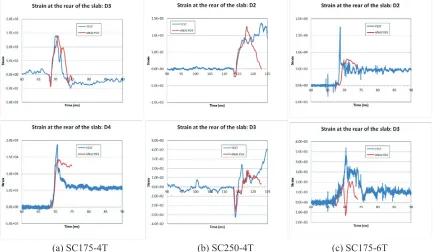
Figure 10. Comparison of Strain Traces (Analysis vs. Test)
G
(a) SC250-4T (b) SC175-6T (c) SC250-6T
G
VALIDATION OF NUMERICAL METHOD
The numerical results were compared with the physical test results to verify the numerical tools and the methodology used in the analyses. The strain and acceleration measurements provide the essential components for the validation of the numerical methods. Acceleration time histories were extracted from the FE model at the nodes nearest the accelerometers in the test, and strain time histories were calculated from the relative distance between the nodes nearest the strain gauges in the test.
The deformed shapes of the SC panels for the representative cases from the tests and analyses are compared in Figure 9. In general, the deformed shapes simulated by the analysis correspond very well with those from the test as shown in Figure 9. The strain time-histories obtained from the tests and analyses are compared in Figure 10. Generally, the strain traces from the analysis compare very well with those from the test in terms of shape, magnitude, and time scale as shown in Figure 10.
From the above, the modeling methodology and the analysis assumptions used in the numerical analysis are verified to be sufficient for predicting the dynamic impact response of a SC panel.
REVIEW OF THE PROPOSED DESIGN METHOD FOR SC WALLS
Recently Bruhl et al. proposed a three step design method which can be applied to the design of SC walls to resist perforation from missile impacts (Bruhl, J. C., 2015). This method will be very useful and practical for designing SC wall because that there was no standardized methods for designing SC wall to resist missile impact.
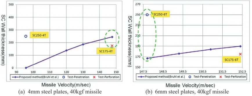
The test results, which were carried out in this study, are compared with the calculation results using the proposed design method in order to identify failure trends of SC walls. The test results show the similar failure trends with calculations as shown in Figure 11. However, a few discrepancies occur between the calculated results and the test results regarding the required concrete thickness for the prevention of perforation. In case of specimen #SC175-4T, actual residual velocity of a missile after perforation of a wall was 85 m/s and this means that the thickness exceeding the calculated wall thickness may be required to resist perforation. In addition, test results of specimen #SC250-6T showed the penetration with the failure depth of nearly panel thickness, but the thickness calculated in order to prevent a perforation is too small as shown in Figure 11(b). Of course, this assessment is based on the limited test results but the above discrepancies may need to be reviewed by a detailed study.
(a) 4mm steel plates, 40kgf missile (b) 6mm steel plates, 40kgf missile
SUMMARY AND CONCLUSIONS
The conclusions of this study drawn from the combined experimental and numerical studies are given below.
1. A series of experimental studies on the local impact behavior of a SC panel were performed using a scale model, and the actual dynamic impact characteristics of SC walls subjected to missile impact load have been confirmed.
2. High Fidelity Physics Based Finite Element analyses for all test conditions using an improved numerical simulation technique have been performed, and the dynamic impact characteristics of SC walls under local impact conditions have been investigated in detail.
3. The numerical simulation tool and the methodology used in the analyses have been validated through a comparison of the actual test and the simulation results. In general, the numerical results are in good agreement with the test results in terms of the failure mode, deformed shapes, and strain traces. In addition, the dynamic impact behavior of the SC panel simulated by the analysis was also consistent with the behavior observed in the tests. These good correlations with the impact test results demonstrate that the numerical simulation method used in this study is robust and reliable in simulating and predicting the local impact behavior of SC walls subjected to missile impact.
From this study, although the local impact behavior of SC walls subjected to missile impact load can be examined via actual impact test and FE analysis, in order to set up a standardized and verified international design method for SC walls subjected to missile impact load, additional research will be needed through various High Fidelity Physics Based Finite Element analyses and actual impact tests for the extended range of missile threats.
REFERENCES
NEI 07-13. (2011). “Methodology for Performing Aircraft Impact Assessments for New Plant Designs, Rev. 8P,” April, 2011.
U.S. Department of Energy. (2006). “Accident analysis for aircraft crash into hazardous facilities (DOE-STD-3014),” Washington, D.C., U.S. Department of Energy.
LSTC. (2013). “LS-DYNA keyword user’s manual v971, R7.0,” Livemore, CA: Livermore Technology Software Corporation.
Bruhl, J. C., Varma, A. H., and Johnson, W. H. (2015). “Design of composite SC walls to prevent
perforation from missile impact,” International Journal of Impact Engineering 75
Bruhl, J. C., Varma, A. H., and Johnson, W. H. (2013). “Design of SC composite walls for projectile
impact: local failure,” SMiRT-22, August 18-23.
K&C. (2015). “Missile Impact Test – SC-Panel Penetration Plan: Basis of Design,” Technical Report. KHNP Central Research Institute. (2015). “Post Test Analysis Report - Missile Impact Simulation