University of Windsor University of Windsor
Scholarship at UWindsor
Scholarship at UWindsor
Electronic Theses and Dissertations Theses, Dissertations, and Major Papers
1-1-2006
A systematic design recovery framework for mechanical
A systematic design recovery framework for mechanical
components.
components.
R. Jill Urbanic
University of Windsor
Follow this and additional works at: https://scholar.uwindsor.ca/etd
Recommended Citation Recommended Citation
Urbanic, R. Jill, "A systematic design recovery framework for mechanical components." (2006). Electronic Theses and Dissertations. 7224.
https://scholar.uwindsor.ca/etd/7224
A SYSTEMATIC DESIGN
RECOVERY FRAMEWORK FOR
MECHANICAL COMPONENTS
by
R. Jill U rbanic
A D issertation
Subm itted to the Faculty o f G raduate Studies and Research
through Mechanical, A utom otive and Materials Engineering
in Partial Fulfillm ent o f the Requirem ents for
the Degree o f D o c to r o f Philosophy at the
University o f W indsor
W indsor, O ntario, Canada
2006
1*1
Library and
Archives Canada
Published Heritage
Branch
3 9 5 W ellington S tre et O tta w a O N K 1 A 0 N 4 C a n a d a
Bibliotheque et
Archives Canada
Direction du
Patrimoine de I'edition
3 9 5 , rue W ellington O tta w a O N K 1 A 0 N 4 C a n a d a
Your file Votre reference ISBN: 978-0-494-42385-1 Our file Notre reference ISBN: 978-0-494-42385-1
NOTICE:
The author has granted a non
exclusive license allowing Library
and Archives Canada to reproduce,
publish, archive, preserve, conserve,
communicate to the public by
telecommunication or on the Internet,
loan, distribute and sell theses
worldwide, for commercial or non
commercial purposes, in microform,
paper, electronic and/or any other
formats.
AVIS:
L'auteur a accorde une licence non exclusive
permettant a la Bibliotheque et Archives
Canada de reproduire, publier, archiver,
sauvegarder, conserver, transmettre au public
par telecommunication ou par Nntemet, preter,
distribuer et vendre des theses partout dans
le monde, a des fins commerciales ou autres,
sur support microforme, papier, electronique
et/ou autres formats.
The author retains copyright
ownership and moral rights in
this thesis. Neither the thesis
nor substantial extracts from it
may be printed or otherwise
reproduced without the author's
permission.
L'auteur conserve la propriete du droit d'auteur
et des droits moraux qui protege cette these.
Ni la these ni des extraits substantiels de
celle-ci ne doivent etre imprimes ou autrement
reproduits sans son autorisation.
In compliance with the Canadian
Privacy Act some supporting
forms may have been removed
from this thesis.
While these forms may be included
in the document page count,
their removal does not represent
any loss of content from the
Conformement a la loi canadienne
sur la protection de la vie privee,
quelques formulaires secondaires
ont ete enleves de cette these.
ABSTRACT
Reverse engineering aims at reproducing an existing object by analysing its dim ensions, features, form , and properties. T he collected data and inform ation m ust be transform ed into pertinent product knowledge at various levels o f detail. In reverse engineering research, em phasis has been placed on recovering the general form o r the p ro d u ct functions. F o r the form recovery tasks, existing techniques focus o n creating com puter aided design (CAD) surface m odels from point cloud data collected from scanning systems. This m odel is m athematically ‘exact’, b u t may be inaccurate due to noise contained in the m odel. As well, the surfaces and edges in the resulting CA D m odel have no functional m eaning, w hich is inappropriate for m echanical com ponents. T he functional related tasks focus o n establishing the com p o n en t’s functional requirem ents and its relationship w ithin the product. F o r effective design recovery, these aspects m ust be com bined and expanded u p o n at various levels o f granularity. T o m eet these challenges, a systematic approach is adopted in a com prehensive m anner to extract the relevant inform ation and transform it into pertinent design knowledge. A m odular design recovery fram ew ork is presented that captures the com p o n en t’s structure, function and feature inform ation at varying perspectives. A n integrated approach that assesses the co m ponent from different perspectives in an innovative m anner leads to a m ore com plete m odel, as no one perspective or set o f tools can provide a com plete, com prehensive engineering representation. T he design recovery fram ew ork can be leveraged to assess or im prove the product design using other design m ethodologies and tools.
ACKNOWLEDGMENTS
Funny things happen in life — sometimes you have to be at the right place at the right tim e for opportunities to occur. Years ago I was in an accident, and doubted my abilities, endurance, and capacity to think. D uring the rehabilitation period, I decided to pursue m y M asters at the University o f W indsor. T he research endeavours pursued by D r. W aguih and D r. H o d a ElM araghy are very similar to the project challenges I pursued in industry, and I w anted to expand my horizons in the realm o f m anufacturing systems. It was a perfect m atch. It had been years since I have had so m uch fun. Obviously the w ork was challenging, b u t I have been exposed to so m any new ideas, intelligent people, and interesting research. T here is so m uch to learn, and so m uch to do. My industrial experience gave m e a solid appreciation for the research being conducted at the IMS Centre, and for D r. W aguih’s m anagem ent style. His knowledge, his sense o f hum our, and his respect and support o f his research students is truly special. I enjoyed working on my Masters research so m uch, I decided to pursue m y P h.D . I sincerely thank my supervisors, D r. W aguih ElM araghy and D r. R obert G aspar, for the opportunity to do so. W ithout the support and encouragem ent presented by these two gendem en, this research w ould have never been conducted. I also w ish to thank D r. Zam ani, D r. M inaker and D r. W u, my com m ittee m em bers, for their guidance and encouragem ent.
T hanks are also due to the staff o f the Mechanical, A utom otive, and Materials Engineering and the Industrial and M anufacturing Systems Engineering D epartm ents for their friendly assistance and support, and to the IMS Centre group, especially D r. H o d a ElM araghy and Ms. Zaina Batal.
TABLE OF CONTENTS
ABSTRACT... iii
ACKNOWLEDGMENTS... iv
LIST OF TABLES...viii
LIST OF FIGURES... xi
GLOSSARY...
xvi
1
INTRODUCTION...1
1.1 Re v e r se En g in e er in g Ba c k g r o u n d... 4
1.2 Pro b lem St a t e m e n t... 13
1.3 Resea r c h Ap p r o a c h... 15
2
REVERSE GEOMETRIC MODELLING... 18
2.1 Sc a n n in g Sy s t e m s...19
2.1.1 Sum m ary...24
2.2 Fil t er in ga n d Po in t Th in n in g...25
2.3 Re g is t r a t io n...26
2.4 Po ly g o n a l Me s h...27
2.5 Su r fa c e Re c o n s t r u c t io n...28
2.6 So urceso f Er r o r...28
2.6.1 C alibration...29
2.6.2 A ccuracy...29
2.6.3 Shadows and Occlusions...29
2.6.4 Surface Reflectivity, and other M aterial P roperties...30
2.6.5 Accessibility...31
2.6.6 M issed Measurements and M is-M easurem ents...31
2.6.7 Mode 11 ing Errors...32
2.1 S u m m a r y ... 33
3
THE SYSTEMATIC DESIGN RECOVERY FRAMEWORK...34
3.1 Ba c k g r o u n d... 34
3.2 Ap pl y in g t h e Za c h m a n Fr a m e w o r kfo r Re v e r s e En g in e e r in g... 38
3.3 Co m po n e n t Le v e l An a l y s is... 40
3.4 Fe a t u r e Lev e l An a l y s i s... 48
3.5 Co n n ec t iv it y Dia g r a ma nd th e De sig n St r u c tu r e Ma t r i x... 53
3.6 Hea lin g Pr o c e s s e s...55
3.7 Testinga n d Va l id a t io n... 58
3.7.1 Sum m ary...64
3.8 Ca se St u d y 1: Cy l in d e r Va lv e Co v e r...65
3.9 Ca se St u d y 2: Po w er St ee r in g Pu m p Pu l l e y... 76
4
SHAPE AND GEOMETRY RECONSTRUCTION...86
4.1 In t r o d u c t io n...86
4.2 Po in t Se le c t io na n d Pr e-pr o c e ssin gt h e Da ta Po i n t s...88
4.3 Po in t Mo d if ic a t io n s... 91
4.4 Ca ptu r in gt h e Cu r v e De sig n In t e n t... 97
4.4.1 Design Intent fo r Linear Segments and Standard Line to Arc Blending 98 4.4.2 Design Intent fo r Circles/Ellipses...99
4.4.3 Design Intent fo r Arc - Arc Combinations...100
4.4.4 Design Intent fo r General Line-Arc Combinations...101
4.4.5 Test fo r Symmetry...102
4.4.6 Capturing Curve Design Intent Summary...103
4.5 Ge o m et r y Co n st r u c t io n Va l id a t io n... 104
4.5.1 Case Study 3: Regulator Gear...108
4.5.2 Discussion...113
4.6 Fe a t u r ea n d Pa tt e r n De t e c t io n... 114
4.6.1 Triangle...115
4.6.2 Square, and Rectangle...116
4.6.3 N -gon...118
4.6.4 Obround and Single D...119
4.6.5 Irregular Shape...120
4.7 Sy ste mo f Fe a t u r e s...120
4.7.1 Linear Pattern...121
4.7.2 Circular Pattern...122
4.7.3 Grid....123
4.7.4 Grid Like...126
4.7.5 Polar...127
4.8 Su m m a r y...130
5 DESIGN IMPROVEMENT METHODOLOGIES...
132
5.1 In t r o d u c t io nto Ax io m a t ic De s i g n...132
5.2 In t r o d u c t io ntoth e Ma n u fa c t u r in g Co m pl ex it y Mo d e l... 134
5.3 Co m po n e n ta n d Fe a t u r e Co d e s...137
5.4 Ca se Stu d y 4: Co n n ec t in g Ro d... 143
5.4.1 Connecting Rod Description...143
5.4.2 Axiomatic Design Approach...149
5.4.3 Incorporating Potential Design Improvements fo r the Connecting R o d 157 5.4.4 Complexity Analysis fo r the Connecting Rod....159
5.5 Ca se Stu d y 5: Tim ing Sc r e w s...163
5.5.1 Introduction...163
5.5.2 Design Recovery Assessment fo r a Velocity Control Timing S crew...164
5.5.3 Reverse Engineering o f Rotary Components...167
5.5.4 Timing Screw Design Functional Requirements...171
5.5.5 Standard Cam Profiles...174
5.5.6 Timing Screw Pocket Design...176
5.6 Su m m a r y... 178
7
FUTURE WORK
188
BIBLIOGRAPHY... 191
APPENDIX A: IDEFO MODELLING OF FORWARD AND REVERSE
ENGINEERING... 210
A .l Ba c k g r o u n d...210
A .2 Fo r w a r d En g in e e r in g IDEFO Mo d e l... 211
A .3 Re v e r s e En g in e e r in g IDEFO Mo d e l...217
APPENDIX B: DESIGN FOR X TABLES... 224
APPENDIX C: SUPPLEMENTARY DESIGN INFORMATION...227
C .l On t o l o g y... 227
C.2 s u pple m e n ta r y d esig nin fo r m a t io nfo rt h e Po w e r St e e r in g Pu m p Pu l l e y... 231
C.3 R E T O O L So ftw a r e Ap pl ic a t io n Pr o t o t y p e...241
APPENDIX D: COMPLEXITY INDEX... 256
D. 1 Pr o d u c t Co m pl ex it y Ex a m pl e [El m a r a g h ya n d Ur b a n ic, 2 0 0 3 ] ... 257
D .2 Co m pl ex it y An a l y sis Fo rth e Re g u l a t o r Ge a r...261
APPENDIX E: FEATURE AND COMPONENT CODE STRUCTURE...266
APPENDIX F...
268
F .l Co n n ec t in g Ro d Su pple m e n ta r y In f o r m a t io n... 268
F.2 Th e Tim in g Sc r e w De sig na n d In s p e c t io n Me t h o d o l o g y... 273
F .2 .1 Design Process...273
F .2 .2 Inspection Process...2 7 8
APPENDIX G: INVESTIGATION OF NON-ITERATIVE CURVE PRIMITIVE
GENERATION TECHNIQUES TO CREATE THE CURVE PRIMITIVES
284
G .l In t r o d u c t io n... 284G .2 Ar c Cr e a t io n... 285
G.3 Er r o r An a l y s i s...290
G .4 El l iptic a l Ar c s...292
G.5 Su m m a r y... 297
LIST OF TABLES
Table 1-1: Feature Type Exam ples for a Single Cylinder Engine C onnecting R o d ...7
Table 1-2: A C om parison betw een Forw ard and Reverse E ngineering... 9
Table 1-3: Zachm an Fram ew ork Representation for Reverse Engineering Present State o f the A rt... 10
Table 1-4: P roposed Zachm an Fram ew ork for Reverse E ngineering... 12
Table 1-5: T est C om ponents Sum mary... 16
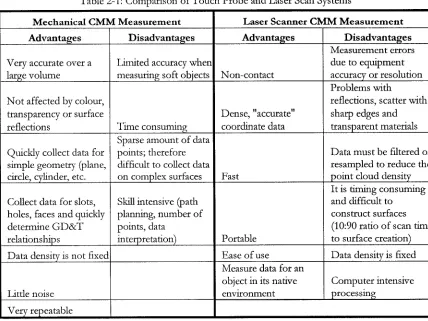
Table 2-1: Com parison o f T ouch Probe and Laser Scan System s...25
Table 3-1: Overview o f the Reverse Engineering Process, adapted from [Tilley, 1998]... 36
Table 3-2: General ‘Physical Level’ Material Characteristics...42
Table 3-3: G eneral ‘D etail Level’ Material Characteristics...43
Table 3-4: F orm Related ‘Physical: W hat’ Cell A ttrib u te s ...44
Table 3-5: Detail: W hat Cell for the C om ponent Analysis... 46
Table 3-6: Feature Sum m ary...48
Table 3-7: G eom etric D im ensioning and Tolerance Relationships...51
Table 3-8: Ancillary Location and Fit Relationships...52
Table 3-9: Feature Summary for Connectivity D iagram s... 53
Table 3-10: Tolerance Grades for M anufacturing P rocesses...58
Table 3-11: Standard FM EA T a b le ... 59
Table 3-12: Generic Failure M odes, Effects and C auses...60
Table 3-13: Failure M odes Analysis T a b le ...62
Table 3-14: Standardized Failure M ode W eights... 62
Table 3-15: C hart R e g io n s... 63
Table 3-16 (a): Low Resolution Analysis for the Cylinder Valve C over using the D esign Recovery Fram ew ork...67
Table 3-16 (b): M edium and H igh Resolution Analysis for the Cylinder Valve C over using the D esign Recovery F ram ew ork... 68
Table 3-17: Design Structure M atrix for the Cylinder Valve C o v e r... 69
Table 3-18: Valve Enclosure Sum m ary...70
Table 3-19: Sealing Surface Sum m ary... 70
Table 3-20: Positional Analysis for the Fastener F eatures...71
Table 3-21: M ounting Flole Sum m ary... 72
Table 3-22: Lip Sum m ary...72
Table 3-23: G D and T Feature R elationships...74
Table 3-24: Auxiliary Feature R elationships...74
Table 3-25 (a): Valve Cover FM EA (partial)...75
Table 3-25 (b): Failure Analysis for the Valve C over...75
Table 3-26: Pow er Steering Pum p Pulley Low Resolution Analysis S u m m ary ...78
Table 3-27: Pow er Steering Pum p Pulley H igh Resolution Analysis S u m m ary ...79
Table 3-28: Pulley System H igh Resolution Analysis Sum m ary...81
Table 3-29: Pulley G D and T D a ta ... 82
Table 3-30: Pulley Ancillary G eom etric D a ta ... 82
Table 4-1: P oint to Angle Relationships...95
Table 4-2: Linear D esign Intent T e s ts ... 98
Table 4-3: Line -A rc —Line R elationships...99
Table 4-5: G eom etry D ifference Analysis...112
Table 4-6: Summary o f the C om m on Shape C haracteristics...115
Table 4-7: Patterns and their Associated ID C o d es...129
Table 5-1: Feature Complexity C o d e ...139
Table 5-2: D efault Factors used to Calculate H for the D ifferent Feature T y p e s ...141
Table 5-3: C om ponent Code for the F o rm ...142
Table 5-4: C om ponent C ode for the Material, Function and E xternal C o n d itio n s ... 142
Table 5-5: T h e C onnecting R od DSM Representation for P roduct and Assembly Related Features...146
Table 5-6: T he Features, Feature Type, Functions, FRs and D P s ...148
Table 5-7: Layer 1 FRs and D P s ...150
Table 5-8: FRs and D P for FR1, Layer 2 ...151
Table 5-9: FRs and D P for FR2, Layer 2 (-ve sign used to indicate a c o n trad ictio n )... 152
Table 5-10: FRs and D P for FR3, Layer 2 ...152
Table 5-11: FRs and D P for FR4, Layer 2 ...153
Table 5-12: FRs and D P for FR1, Layer 3 ...153
Table 5-13: T he Final D ecom position for F R 1 ... 154
Table 5-14: D ecom position o f FR4.3 (FR and D P Prefix ‘4.3.’ eliminated for clarity)... 156
Table 5-15: M apping the Design Recovery Feature to the Axiom atic D esign D e c o m p o sitio n ...157
Table 5-16 (a): Individual Feature Codes and Complexity Aspects for the Connecting R o d ...160
Table 5-16 (b): Feature and C om ponent Complexity Analysis for the C onnecting R o d ...160
Table 5-17 (a): Individual Feature Codes and Complexity Aspects for the M odified Connecting R o d ...162
Table 5-17 (b): Feature and C om ponent Complexity Analysis for the M odified Connecting R o d ...162
Table 5-18: Fligh R esolution Tim ing Screw Sum m ary...166
Table 5-19: Low Resolution Tim ing Screw Sum m ary... 167
Table 5-20: D ecom position o f First Level F R s ...172
Table 5-21: D ecom position o f F R 2 ...173
Table B -l: Process C om parison Overview: Material, V olum e and Size...224
Table B-2: Process Com parison Overview: Characteristics, Costs and D esign C onsiderations...225
Table B-3: Process D esign C onsiderations...226
Table C -l: Summary for the Clearance Floles...233
Table C-2: Locating H ole Pattern D S um m ary...234
Table C-3: Blending Fillet Sum m ary...235
Table C-4: V G roove Sum m ary...236
Table C-5: Redesign Pulley M ounting H ole Sum m ary...237
Table C-6: Locating FIolc A1 Summary for the W ater P u m p /A k -C o n d itio n in g Pulley... 238
Table C-7: Summary for the V G roove G eom etry w hen Analysing the Pulley System... 239
Table C-8 (a): G D and T Inform ation for the Pulley...239
Table C-8 (b): Ancillary G eom etry Inform ation for the Pulley...240
Table C-9: G eom etry Failure M odel Analysis for F M E A ...240
Table D -3 (a): ‘Feature Type’ Analysis for the Mass Air Flow B ody...260
Table D -3 (b): ‘Feature T ype’ Analysis for the Mass Air Flow B o d y ... 260
Table D -3 (c): ‘Feature T ype’ Analysis for the Mass A ir Flow B o d y ... 260
Table D-4: Positional N om inal Values and T olerances...262
Table D-5: Individual Feature Complexity Aspects Analysis for the Regulator G e a r ... 263
Table D -6 (a): Feature Type Analysis for the Regulator G e a r...264
Table D -6 (b): Feature T ype Analysis for the Regulator G ear...264
Table D -6 (c): Feature Type Analysis for the Regulator G e a r...264
Table E -l: F orm Related Fields for the C om ponent C ode...266
Table E-2: Material Related Fields for the C om ponent C o d e ...267
Table E-3: Envelope Related Fields for the C om ponent C ode...267
Table E-4: O perating C onditions Related Fields for the C om ponent C o d e ... 267
Table F -l: Contextual, C onceptual and Logical Layers for the C onnecting R o d ... 268
Table F-2: Physical and D etail Layers for the C onnecting R o d ...269
Table F-3: Small E n d Bore Sum m ary...270
Table F-4: Big E n d Bore Sum m ary...270
Table F-5: W eight Saver Sum m ary... 271
Table F-6: Connecting R od and M ating C om ponent M easurem ents...272
Table F-7: Input Param eters for a Tim ing Screw ...276
Table G -l: Summary o f Circles Created Using 3 P oints...286
Table G-2: Radius and Centre Points Using Chordal Analysis...288
Table G-3: Radius and Centre Points Using the Least Squares C hordal A nalysis... 289
Table G-4: Radius and Centre Points Using the Algebraic Fit M eth o d ... 290
Table G-5: Summary o f Circle Analysis R esults... 291
Table G-6: Summary o f Ellipse A nalysis...293
LIST OF FIGURES
Figure 1-1: Elem ents th at Influence the Final D esign... 2
Figure 1-2: G eneral IDEFO Activity B lo c k ... 5
Figure 1-3: Reverse Engineering... 6
Figure 1-4: Connecting R od and P isto n ... 7
Figure 1-5: Traditional Point Cloud to CA D M odel T ransform ation Steps (created using Paraform ® ) [Metris, 2 0 0 6 ]... 14
Figure 1-6: Valve Cover, Pow er Steering Pum p Pulley, C onnecting Rod, Tim ing Screws, and Regulator G e a r... 16
Figure 2-1: Reverse G eom etric M odelling... 18
Figure 2-2: Zeiss CM M and Probe A and B Travel L im its... 19
Figure 2-3: Laser Triangulation for M easuring D im ension D [Feng, 2002]...21
Figure 2-4: Images Seen by the Laser and Camera for Active Triangulation [Teutsch, 2003]...22
Figure 2-5: M oire Fringe [Ypsilos, 2004] and Image D istorting the Fringe [Bujakiewicz et al, 2004]...22
Figure 2-6: Tim e o f Flight System [Ypsilos, 2004]...23
Figure 2-7: Grey Scale for CT Scanning System [StrokeStop, 2000]...23
Figure 2-8: Single Slice T om ogram o f a Cylinder Flead [Flisch et al, 1999]...24
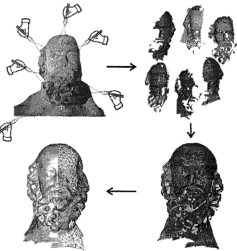
Figure 2-9: M ultiple Scans, Point Clouds D ata, Registration and Surface G eneration for a Sculpture [Karbacher et al, 2001]... 27
Figure 2-10: Shadow and O cclusion...30
Figure 2-11: Partial O cclusion and D iscontinuities... 30
Figure 2-12: Variable P oint Cloud D ata Set due to M easurem ent V elocity...31
Figure 2-13: Am biguous 2D Reconstruction from Points [Bernardini et al, 1999]... 32
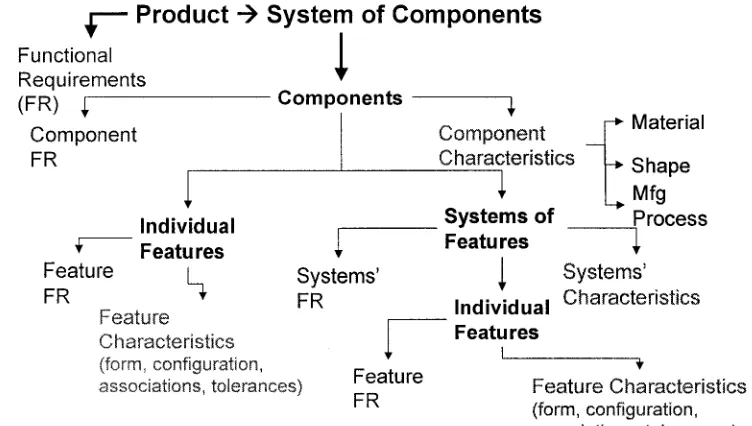
Figure 3-1: P roduct T axonom y...35
Figure 3-2: Resolution Levels for the D esign Recovery Process...38
Figure 3-3: D esign Recovery Fram ew ork (C om ponent and Feature Levels), adapted from Z achm an [2002]...40
Figure 3-4: T h e Coupling o f the C om ponent A ttributes...41
Figure 3-5: C om ponent Level Analysis Sum m ary...47
Figure 3-6: G eneral C om ponent A ttribute T ax o n o m y ... 47
Figure 3-7: Design Param eters for D ifferent Feature Types... 50
Figure 3-8: General Feature A ttribute T axonom y... 52
Figure 3-9: Connectivity D iagram for a Single Cylinder Engine Valve C over...54
Figure 3-10: Connectivity D iagram for a Single Cylinder Engine Valve C over Including Transition G e o m e try ... 54
Figure 3-11: D SM Configurations [G uenov and Barker, 2004]...55
Figure 3-12: D raft for a D ie Cast C onnecting R o d ... 56
Figure 3-14: Charting the FM EA R esults...63
Figure 3-15: (a) T he Valve Cover, (b) the Rocker A rm Assembly, (c) the Engine A ssem bly... 65
Figure 3-16: D atum Features and D ata V alues...71
Figure 3-17: G asket Sealing Surface C reatio n ...73
Figure 3-18: Final CA D M o d el... 73
Figure 3-20: Pow er Steering Pum p P ulley...77
Figure 3-21: CA D M odel o f Reconstructed Pulley...80
Figure 3-22: N ew Pulley to Drive the W ater Pum p and Pow er Steering Pum p — C A D m odel and m achined part, and Interfacing D a m p e n e r...83
Figure 4-1: P oint D istribution Types on the L ayers...88
Figure 4-2: Boundary Edge D etection w ith Sorted P o in ts...89
Figure 4-3: Identifying Features from N oise C hallenges...89
Figure 4-4: Boundary Labels...91
Figure 4-5: Adjsuting N oisy P o in ts ...92
Figure 4-6: Parse Polyline E x a m p le ...93
Figure 4-7: Circle R elationships... 94
Figure 4-8: Dynamic ‘Filtering’ Algorithm U sed to G enerate P o in ts...95
Figure 4-9: Feature T ransition G eom etry E xam p les...96
Figure 4-10: Original Points, M odified Points and C onstructed Arcs for a French Curve T e m p la te ...97
Figure 4-11: G enerated Curve Primitives and D esired Curve Prim itives...98
Figure 4-12: N orm al Fillet E x am p le... 99
Figure 4-13: T est for Concentricity and C orrected G eom etry...100
Figure 4-14: A rc to A rc C om binations...100
Figure 4-15: A rc Fillets to Ensure Tangency...100
Figure 4-16: Arc-Arc-Arc Fillet E x a m p le ...101
Figure 4-17: R andom Line - Arc C om binations...102
Figure 4-18: Setup for Symmetry A ssessm en t...103
Figure 4-19: G eom etric Tolerancing and D im ensioning Symbols...104
Figure 4-20: Circle T e s t... 105
Figure 4-21: French Curve Analysis Results (not to scale)... 106
Figure 4-22: Cylinder Valve Cover: B o tto m ...107
Figure 4-23: Variations from the Surface... 108
Figure 4-24: Regulator G ear System and D am aged P a r t ...109
Figure 4-25: Pow er W indow Regulator G e a r... 109
Figure 4-26: Positional M easurem ents...I l l Figure 4-27: G eom etric Healing (Modifying) Edge E 2 ...112
Figure 4-28: Final P art G eom etry...113
Figure 4-29: Square and Rectangle Feature in R andom O rientation in Space...117
Figure 4-30: Inscribe Circle for an N -gon w ithout and w ith Fillets...118
Figure 4-31: O b ro u n d Shape...119
Figure 4-32: Single D S h a p e ...119
Figure 4-33: Irregular Shape Critical F eatures...120
Figure 4-34: C om m on Planar P a tte rn s... 121
Figure 4-35: Linear A rrangem ent o f Features... 122
Figure 4-36: Circular P attern o f F eatures...123
Figure 4-37: Radial and Axial Circular G rids...123
Figure 4-38: Case 1 - Standard G rid...124
Figure 4-39: Case 2 — Rectangular P a tte rn ...125
Figure 4-40: Case 3 - C orner P a tte rn ...125
Figure 4-41: Partial G rid and M ethod o f D etecting an E m bedded Rectangle P a tte rn ... 126
Figure 4-42: Staggered G rid Case 1 and Case 2 ...127
Figure 4-44: Polar G rid P a tte rn ...129
Figure 4-45: Algorithm Sum m ary...131
Figure 5-1: Design Coupling...133
Figure 5-2: Transform ing the Design Recovery Fram ew ork Inform ation into the A D Matrix F o rm a t...134
Figure 5-3: Elem ents o f C om plexity...135
Figure 5-4: M anufacturing Complexity Cascade...136
Figure 5-5: Feature C o d e s...138
Figure 5-6: Functioning Connecting R o d ... 144
Figure 5-7: Connecting R od Features...145
Figure 5-8: Connecting R od Connectivity D ia g ra m ...147
Figure 5-9: C om ponent Level D e sig n ...149
Figure 5-10: D ecom posing the Design Problem and Zigzagging betw een D o m a in s ... 150
Figure 5-11: C onnecting R od FR D eco m p o sitio n ...151
Figure 5-12: A Com parison o f the Relative E ffo rt for each A ttribute for the Base C onnecting R o d ...161
Figure 5-13: A C om parison o f the Relative E ffo rt for each A ttribute for the M odified C onnecting R od D esign...163
Figure 5-14: Variable Pitch Screw T erm inology...164
Figure 5-15: Rotary C om ponent A lignm ent... 168
Figure 5-16: Relationship betw een Rolled to Unrolled P oints...168
Figure 5-17: A Com parison o f the Unrolled to an U nw ound Helix C urve... 169
Figure 5-18: Variable Pitch Displacem ent D iagram ...170
Figure 5-19: Calculated Linear Velocity...171
Figure 5-20: Acceleration Curves U sed in Cam D esign...175
Figure 5-21: Variable Frequency and T ransition Zones (Top V iew )...176
Figure 5-22: Variable Pocket G eom etry... 177
Figure 5-23: Incom ing Taper Design and Tim ing Screw w ith Lead in T a p e r...177
Figure 5-24: Design Flow using the D esign Recovery F ram ew ork ...180
Figure 6-1: Design Recovery Process Flow Sum mary... 183
Figure A -l: Engineering D e sig n ...210
Figure A-2: Reverse Engineering D esign...211
Figure A-3 (a): A0 N o d e for P roduct D evelopm ent, Elem ents A l — A 3 ... 211
Figure A-3 (b): A0 N o d e for P roduct D evelopm ent, Elem ents A 4 — A 7 ... 212
Figure A-4: A l N o d e - D efine N e e d ...213
Figure A-5: A2 N o d e — Design the Product, Elem ents A2.1 — A 2 .3 ...214
Figure A-6: A 2 N o d e - Design the Product, Elem ents A2.4 - A 2 .6 ... 215
Figure A-7: A3 N ode — Plan the M anufacturing Process, Elem ents A3.1 — A 3 .3 ... 216
Figure A-8: A3 N ode — Plan the M anufacturing Process, Elem ents A 3.4 — A 3 .6 ... 217
Figure A-9: A0 N ode — Reverse E ngineering...218
Figure A-10: A l N ode — Hypothesize N e e d ...219
Figure A -l 1: A2 N ode — G ather D a ta ...220
Figure A-12: A3 N o d e — D educe “D etailed” Functional M o d e l...221
Figure A-13: A2.2 N o d e — D ocum ent Product, Elem ents A2.2.1 — A 2 .2 .3 ... 222
Figure A - l 4: A2.2 N o d e — D ocum ent Product, Elem ents A2.2.4 — A 2 .2 .6 ... 223
Figure C -l: Function T axonom y...228
Figure C-2: F orm T a x o n o m y ...230
Figure C-4: SAE Standard G roove D a t a ... 236
Figure C-5: Pulley System Fleight M easurem ents...238
Figure C-6: FM EA Results C h a rt...240
Figure C-7: Set up Sheet Inform ation...244
Figure C-8: Form al System Related In fo rm a tio n ...245
Figure C-9: Form al Physical Inform ation (part 1)...246
Figure C-9: Form al Physical Inform ation (part 2)...247
Figure C-10: Peripheral C om ponent Inform ation and D a ta ...248
Figure C - ll: Form al Feature Inform ation for the C o m p o n e n t...249
Figure C-12: Form al D etail C om ponent Inform ation...250
Figure C - l 3: Form al Specific Feature Related Inform ation for the Crankshaft M ounting Bolt Clearance H ole (part 1)...251
Figure C-14: Form al Specific Feature Related Inform ation for the Crankshaft M ounting Bolt Clearance H ole (part 2)...252
Figure C -l 5: D om ain M o d e l... 253
Figure C -l 6: Design Recovery Fram ew ork F low ...253
Figure C-17: D om ain Interactions (part 1 )...254
Figure C -l 8: D om ain Interactions (part 2 )... 255
Figure D - l: Mass A ir Flow Body Features...258
Figure D-2: Complexity Analysis for the M A F B ...261
Figure D-3: Regulator G ear with D am aged and W orn T e e th ...262
Figure D-4: Scanned D ata and Feature Labels for the Pow er W indow Regulator G ear... 262
Figure D-5: Final P art G eom etry...263
Figure D-6: A C om parison o f the Complexity Index Values for the M AFB and the Regulator G e a r...265
Figure F -l: Tim ing Screw Design Process F lo w ...273
Figure F-2: Cycloidal and Third H arm onic Accelration C urves...276
Figure F-3: Final T rim m ed M odel (Lead o ut E n d Partially H idden to Show P ocket G eom etry)...277
Figure F-4: T ool P ath Verification M o d e l...278
Figure F-5: Inspection Process F lo w ...279
Figure F-6: P oint cloud D ata (without O utside D iam eter Points)...279
Figure F-7: Critical Points (Diam eter less than 40 m m )...280
Figure F-8: U nw ound Critical P o in ts...280
Figure F-9: U nrolled and U nw ound Edge P o in ts ...280
Figure F-10: Velocity Profile for the Sample P a r t...281
Figure F - l l : Velocity Profile for Sample P art Using Selected P o in ts... 282
Figure F-12: Acceleration Profile...283
Figure G -l: Basic 2-D Primitive Curves and D ata R ecords...284
Figure G-2: F ro n t and Side View o f H ole Tem plate, and Points on A rc used for D ata Analysis...285
Figure G-3: T hree Points Circles from First 10 D ata P o in ts ...286
Figure G-4: Circle C entre by Intersecting T w o Lines Perpendicular to Tw o Non-Parallel C h o rd s ...287
Figure G-5: Chords used for Circle Analysis...288
Figure G-6: Points Representing an E llip se ...292
Figure G-7: Estim ates o f the Arc R adius...292
GLOSSARY
2D.
Tw o D im ensional3D.
Three D im ensional3D-2D parts.
Stamped com ponents consisting o f a thin sheet w ith a free form shap<3D-3D parts.
Castings or weldm ents consisting o f engineered and free form shapesAD.
Axiomatic DesignAF.
Algebraic FitCAD.
C om puter Aided D esignCAM.
C om puter A ided M anufacturingCAPP.
C om puter A ided Process PlanningCCD.
Charge Couple DeviceCMM.
Coordinate M easuring M achineCNC.
C om puter Numerically ControlledCT.
C om puter Tom ographyCircumcircle.
Circle created from three pointsDFX.
Design for X (Machining, Casting, Assembly, and so forth)DoDAF.
U.S. D epartm ent o f D efense A rchitecture Fram ew orkDP.
Design Param eterDSM.
Design Structure M atrixE2AF.
E xtended E nterprise A rchitecture Fram ew orkFE.
Forw ard EngineeringFEA.
Federal E nterprise A rchitectureFR.
Functional Requirem entsICP.
Iterative Closest P ointIDEF.
Integrated D E FinitionIGES.
Initial G raphic Exchange StandardGD&T.
Geom etric D im ensioning and TolerancingGO continuity.
E n d point continuityG1 continuity.
Tangency continuityMA.
M orphological AnalysisMRI.
Magnetic Resonance ImagingNIST.
N ational Institute o f Standards and TechnologyPoint cloud data.
Spatial coordinates representing the surfacePolyline.
Point-to-point line segmentsPY.
Process VariableQFD.
Quality Function D eploym entRE.
Reverse EngineeringSAE.
Society o f A utom otive EngineersSTEP.
STandard Exchange o f P roduct dataSTL.
Standard Triangulation LanguageTRIZ.
Theory o f Inventive P roblem SolvingC h a p t e r 1
IN T R O D U C T IO N
1
INTRODUCTION
Reverse engineering techniques are applied to generate a part m odel w here there is no existing docum entation or it is no longer up to date. Form al reverse engineering (RE) generally refers to the process o f reproducing an existing object (com ponent or product), w ithout the aid o f fom ial specifications such as drawings or a com puter m odel by analysing the object’s physical dim ensions, features, and material properties. In the general sense, ground-up reverse engineering is challenging as it may require engineers in different disciplines to capture all o f the ideas related to the com ponents and their interrelationships w ithin a given system. T h e goal o f reverse engineering is to construct a characterization o f the p ro d u ct by accum ulating all o f the technical data and knowledge o f how a product works.
Specifications
& S tandards
NEED
R esources: Time and Materia
Econom ics Environm er
Tradeoffs Constrai:
Design
O ptions
Final D e s ig n
Health & Safety T ech n olo gy
W o rkfo rce
Figure 1-1: Elem ents that Influence the Final Design
Consequently, w hen reverse engineering an engineered co m ponent there m u st be a m ethodology for recognizing the design intent o f the features, and systems o f features in b o th the physical (form) and logical (FR) domains.
T h e classical definition o f reverse engineering has negative connotations. Reverse engineering m eant m aking a copy o f an existing com petitors product. H ow ever, reverse engineering is useful as a benchm arking tool for design recovery, product redesign or for a new pro d u ct introduction [Otto and W ood, 1996]. Presently, reverse engineering refers to the process o f creating a three dim ensional (3D) geom etric m odel from a physical object. This in essence is n o t reverse engineering, b u t reverse surface modelling, w hich is a fundam ental building block o f the reverse engineering process. D evelopm ents in data collection devices (3D scanning and digitizing instrum ents) and processing techniques (converting the acquired data to a surface m odel) have lead to efficient part - to - CA D m odel processes [Langbein, 2003], [Krause et al, 2003], [Fischer and Park, 1998], [Fischer and Smolin, 1997], [Limaien and ElM araghy, 1999],
[Fisher, 2004], [Thom pson et al, 1999]. T he need for reverse engineering typically arises when:
• D raw ings/m odels have been created, b u t the com ponents have been m odified during iterative prototyping/design, testing and use; hence, the existing docum entation is no longer relevant.
• C om paring a fabricated part to its CA D description or to a standard item for inspection a n d /o r quality assurance purposes [Yuan et al, 2001].
• D ocum enting a n d /o r m easuring cultural objects (sculpture or other artwork) or artefacts in archaeology, palaeontology and other scientific fields [Tsakiri et al, 2003],
• G enerating data to create dental or surgical prosthetics, or fitting clothing or footw ear to individuals [Au and Yuen, 1999], Kolm anic and Guid, 2003].
T h e reverse engineering (reverse surface modelling) tools focus on efficient and ro b u st autom atic generation o f free form shapes from point cloud data [Attene and Spagnuolo, 2000], [Azem ikov and Fischer, 2003], [Bernardini et al, 1999], [Krause et al, 2003], [K ruth and K erstens, 1998], [Limaiem et al, 1996], [Motavelli, 1998], [Zhang et al, 2002], [Zhongwei and Shouwei, 2003]. Researchers are concerned about m esh construction, [Chappuis et al, 2004], [Li et al, 2003], [Fischer, 2002], [Botsch and K obbelt, 2001], [Karbacher et al, 2001, 1999], [Dey et al, 2001], [Liu and Ma, 2001], [Sun et al, 2001], [Attene and Spagnuolo, 2000], [Bradley et al, 1999], [Turk and Levoy, 1994], surface continuity [Chappuis et al, 2004], [K nopf and Sangole, 2004], [Krause et al, 2003], [Huang and Meng, 2001], sharp edge detection [Vanco and B runnett, 2004] and reducing m easurem ent and registration noise [Vadde et al, 2004], [Page et al, 2003], [Kverh and Leonardis, 2002], [ElMaraghy and Rolls, 2001], [Luck et al, 2000], [Yau, et al, 2000], [Chalermwat, 1999], [Gagnon et al, 1998], [Eggert et al, 1994]. T here are several state o f the art comm ercial reverse engineering software packages, such as Paraform ® , w hich are very powerful. How ever, the reconstructed surfaces and edges have no functional meaning, m ay have self -intersections, and may n o t be continuous. T hese issues m ake it difficult to edit the base geom etry for subsequent design m odifications and m anufacturing tool path creation.
cannot effectively deal w ith this type o f geometry, as the reverse engineering m odelling tools capture a precise best-fit polynomial representation o f the data, b u t do n o t generate a functional engineering representation. T he data will contain noise due to m easurem ent errors, m anufacturing variations, and wear and damage on the part. This noise is n o t G aussian (i.e. it does n o t have a zero m ean value and a normally distributed variation). T h e resulting best-fit geom etry will n o t reflect the designer’s intent. N o t only m ust the individual features within the co m ponent be reconstructed accurately, there are structural relationships. T here are aggregates o f features; therefore, there should be a m ethodology to recognize this. W ith engineered com ponents, the feature shapes are neither arbitrary, no r is their pattern o f arrangem ent. T here are identifiable characteristics at the feature level and the system level. Several researchers recognize that ‘designed in’ geometric relationships exist, and that exploiting these geom etric constraints (e.g. prim itive shapes and symmetry) im proves the reconstruction process for the design features [Benko and Varady, 2004], [Benko et al, 2002], [Benko et al 2001], [Gao et al, 2004], [Langbein et al, 2004], [Langbein, 2003], [Langbein et al, 2001], [Fisher, 2004], [Tangelder et al, 2003], [Thom pson et al, 1999], [Werghi et al, 2002], [Werghi et al, 1999]. G eneral shape knowledge can allow recovery even w hen data is very noisy, sparse or incom plete [Werghi et al, 2002], [Fisher, 2004]. T he geom etry should be com pared based on similarity m easures for bo th the individual elements and their arrangem ent. M ost o f the existing research focus has been on reconstructing the general form or individual features using data from scanning systems. A t the system level, neither a pattern m atching m ethodology has been perform ed, no r have the functional requirem ents been taken into consideration w hen recovering the feature’s form. T o reconstruct the p ro d u ct architecture, inform ation and data m ust be collected from several sources. This cannot be autom ated, b u t multi-level, intelligent, interactive tools can be developed to assist in transform ing the collected data into relevant design knowledge that can b e then edited for dow nstream applications.
1.1
REVERSE ENGINEERING BACKGROUND
The conditions or constraints required for the function to p ro d u c e th e C O R R E C T
outputs Control
Input
---Transform ed by the function to p ro d u ce the outputs
•r.. -« & i i f R ;
■W i H A«Mte
— ► Output
D ata or objects to p ro d u ced by the function
Mechanism
The m eans that s u p p o r t the execution o f the function
Figure 1-2: General IDEFO Activity Block
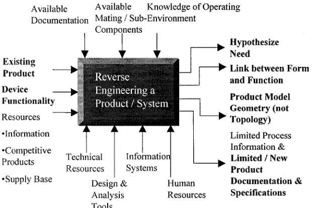
A sample o f the reverse engineering IDEFO m odel is presented here. W hen reverse engineering, a deductive process is com bined with data gathering techniques to m igrate from a physical ‘W H A T ’ to the hypothetical W H Y ’ and a conjectured final model. T he existing product, related docum entation, and the functions the pro d u ct perform s are inputs in to the reverse engineering system. T he device functional requirem ents, the link betw een the form and function, the product m odel and the docum entation are the desired outputs. T h e m echanism s to generate the desired output from the input are the technical resources, the design and analysis tools, the inform ation systems and the hum an resources. T h e controlling aspects o f the reverse engineering process consist o f the available pro d u ct docum entation, available inform ation with regard to the m ating com ponents and the knowledge o f the operating environm ent. This is illustrated in Figure 1-3. T he fabrication techniques are essentially o u t o f the reverse engineering design loop, although the fabrication techniques influence the final model.
inform ation gathered by studying the product into knowledge that can be cascaded to the fabrication, in sp ectio n an d testing processes.
A vailable A vailable K now ledge o f O perating
D ocum entation M ating / Sub-E nvironm ent Com ponents
Existing Product Device Functionality R esources •Inform ation •C om petitive Products •Supply B ase
Inform ation System s Technical
R esources D esign & A nalysis Tools
H um an R esources
Hypothesize Need
► Link between Form and Function Product Model Geometry (not Topology) L im ited P rocess Inform ation & Limited / New Product
Documentation & Specifications
Figure 1-3: Reverse Engineering
This goes beyond capturing the general shapes o f the product. T h e factors th at need to be considered are the:
• Functional, form and fabrication features,
• Interface, and assembly features, and the
• M aterial and tolerance characteristics.
Functional Features
Feature A: Oil Splasher (lubricates engine case interior) Feature B: Lubrication Hole (1 per side)
Feature C: Oil Grooves (3 per side) Assembly Features:
Feature E: Horizontal Split Feature F: Mounting holes (2)
Figure 1-4: Connecting R od and Piston
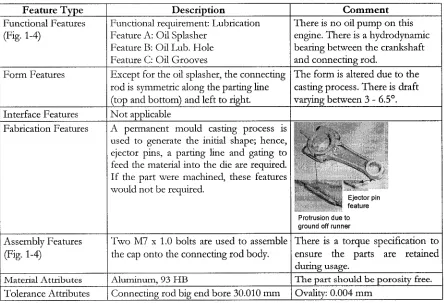
Table 1-1: Feature Type Examples for a Single Cylinder Engine C onnecting R od
Feature Type Description C om m ent
Functional Features (Fig. 1-4)
Functional requirement: Lubrication Feature A: Oil Splasher
Feature B: Oil Lub. Hole Feature C: Oil Grooves
There is no oil pum p on this engine. There is a hydrodynamic bearing between the crankshaft and connecting rod.
Form Features Except for the oil splasher, the connecting
rod is symmetric along the parting line (top and bottom) and left to right.
The form is altered due to the casting process. There is draft varying between 3 - 6.5°.
Interface Features N o t applicable
Fabrication Features A permanent m ould casting process is
used to generate the initial shape; hence, ejector pins, a parting line and gating to feed the material into the die are required. I f the part were machined, these features would not be required.
■ M
E je c to r pin ^ “* 4 fe a tu re P ro tru sio n d u e to g ro u n d off ru n n e r
Assembly Features (Fig. 1-4)
Two M7 x 1.0 bolts are used to assemble the cap onto the connecting rod body.
There is a torque specification to ensure the parts are retained during usage.
M a te ria l A ttr ib u te s A lu m in u m , 93 FIB T h e p a r t s h o u l d b e p o r o s ity free.
Tolerance Attributes Connecting rod big end bore 30.010 m m Ovality: 0.004 m m
Table 1-2: A Comparison between Forw ard and Reverse Engineering
D escription Forward E ngineering Reverse E ngin eering
Functional Features
Designed elements are defined explicitly to satisfy the need. The designs are optimized based on the problem ’s constraints [Pahl and Beitz, 1988], [Suh, 2001], [Dixon and Poli, 1995], [ElMaraghy and ElMaraghy, 1994].
Features are implicidy defined or deduced.
Form features Geometry, Topology and Structure are explicitly
defined and optimized.
Process considerations influence the shape.
Geom etry and Structure are
deduced. D istortion due to wear,
corrosion, and other causes
introduce noise into the model.
A geometric healing process m ust be applied to address these issues.
Interface features (places at which independent and unrelated systems meet)
An interface may consist o f a modular or customized structure. A modular com ponent has
standardized features and dimensions (i.e.,
modular fixture components used for a variety of parts). A customized structure utilizes an unique design specific to its purpose (i.e. custom work holding devices).
Implicidy defined and depends on the availability o f super structure, sub com ponents and commercial product information.
Nom inal values The designer explicidy defines nominal values for ease o f understanding and cost minimization throughout the design, manufacture, and usage phases.
The values can be distorted due to the quality o f the part(s) being
analysed. A dimensional healing
process must be applied to address these issues.
Tolerances The designer explicitly defines tolerances to
balance manufacturing feasibility with overall product quality.
Dimensional and geometric
tolerances are implicidy defined due to assumed functionality and process capabilities.
Manufacturing process
The manufacturing processes are explicidy
(a nd/or implicidy) defined. They are an im portant aspect in design and detailing the final product
(concurrent engineering and DFX), and
determining the product testing, verification and process capability requirements [Benko et al, 2002], [Tichkiewitch and Veron, 1998], [Van Vliet et al, 1999], [Dixon and Poli, 1995], [Wiendahl, and Scholtissek, 1994].
Some original processes may be
inferred by characteristic tool
marks, and analysis o f physical
properties; however, this
information may be changed if the
remanufacturing volumes and
other constraints are different.
Process capability
The process capability requirements are explicidy (and/or implicidy) defined.
Process capability = conformance to specification (or product quality and reliability aspects)
Process capability and other
quality related inform ation cannot be deduced.
Overall Shape, dimensions, tolerances and specifications
defined by design.
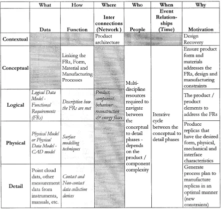
T h e state o f th e a rt fo r reverse engineering o f physical c o m p o n e n ts is re p re se n te d u sin g a m o d ificatio n o f th e Z a c h m a n F ram ew o rk [Z achm an, 2002] in T a b le 1-3. T h e Z a c h m a n fram ew o rk w as originally created fo r developing a n d /o r d o c u m e n tin g en terp rise w ide in fo rm a tio n system s architecture. T h e fram ew o rk m atrix consists o f co lu m n s th a t p ro v id e
various focii o f th e overall architecture a n d row s, w h ich p ro v id e th e vario u s p erspectives
w ith in th e architecture. T h e detail layer has b e e n a d d e d fo r this depiction.
Table 1-3: Zachman Framework Representation for Reverse Engineering Present State of the Art
What H ow Where Who W hen Why
Data Function
Inter connections
(N etw ork ) People
E vent Relation
ships
(T im e) M otivation
Contextual Product architecture Design Recovery C onceptual Linking the FRs, Form, Material and Manufacturing Processes Multi discipline resources required to navigate between the conceptual to detail phases - depends on the product / component complexity Iterative cycle between the conceptual to detail phases Ensure product form and materials addresses the FRs, design and manufacturing constraints L ogical Fogical Data Model -Functional Requirements (FRs) Description how the F R s are met
Product, component behaviour reconstruction <& energy flows
The product / product elements to address the FRs
Physical
Physical Model or Physical Data Model -C A D model
Surface modelling techniques
Produce replicas that have the desired form, physical, mechanical and interface characteristics D etail Point cloud data, other measurement data from instruments, manuals, etc. Contact and Non-contact data collection devices Generate process plan to manufacture replicas in an optimal manner (new
constraints)
a straightforw ard m anner to accom m odate changes. T he part design and the m anufacturing processes are highly coupled. U nderstanding the interconnections betw een the dom ains is necessary for effective design recovery, design m odifications and m anufacturing process planning. T he proposed Zachm an fram ew ork for the reverse engineering o f engineered com ponents is presented in Table 1-4.
Table 1-4: Proposed Zachm an Fram ew ork for Reverse Engineering
What H o w Where Who W hen Why
Data Function
Inter connections
(N etw ork )
People
E vent Relation
ships (T im e)
M otivation
Contextual Product
architccmre •fiillsif.. wmmw0Mm
Design Recovery
Conceptual
Linking the II P . la inn. Material and Manufacturing Processes Product Functional Requirement'- anti Interface link Multi discipline between the conceptual to detail phases - depends on the product or com ponent complexity Iterative cycle between the conceptual to detail phases Ensure product form and materials addresses the FRs, design and manufacturing constraints Logical Logical Data Model - Functional Requirements (FRs) use Product Design Functional vocabulary (NIST) [Hirtz et al, 2002]
Description how ilie 1 ID are met
I’n nil id / Element
Finn uon.il Requirements link
T he product / product elements to address the FRs
Physical
Physical D ata Model - CAD model Functional modelling technique-;, consider Design and
s
. techniquesI’n >dud Form and Material - Process link
Produce replicas that have the desired form, physical, mechanical and interface characteristics D etail Point cloud data, other measurement data from instruments, manuals, etc. Contact and non-contact data collection devi cv- Process con siderations
Tolerances, Feature
V'sociations
Generate process plan to manufacture replicas in an optimal m anner (new
1.2 PROBLEM STATEMENT
M echanical com ponents are designed to satisfy a specific need for a given set o f constraints: the form , functions, material and the m anufacturing processes are all interrelated. T he com p o n en t interfaces w ith other com ponents. T he features, nom inal values o f the dim ensions, and the tolerances are selected for functionality, assemblability, ease o f understanding, and cost m inim ization throughout the design, m anufacture, and usage phases.
N o com prehensive reverse engineering m ethodology exists th at assesses an engineered com p o n en t at various levels o f granularity, linking the form and functional aspects in a systematic m anner. T he functional requirem ents m ust be taken into consideration w hen recovering the design param eters for a feature’s form and its structural relationships. T he m odel should be extensible, i.e. it should integrate sm oothly into o th er design and m anufacturing tools. It should be easy to analyse the reconstructed design and incorporate subsequent design modifications. A n innovative, holistic approach needs to be taken in order to com prehensively capture the designer’s intent and m odel the p ro d u c t/c o m p o n e n t/fe a tu re w hen perform ing reverse engineering tasks.
T he goals o f this research are to develop a framework, a set o f m ethodologies, and reverse engineering design tools to assist an engineer to:
(i) C onstruct an ideal geom etric m odel that captures the intended geom etric regularities,
(ii) Identify, extract and ignore (if necessary) process related irregularities and geom etry,
(iii) Capture the relevant engineering specifications by linking m ultiple perspectives in a structured, organized m anner, and
(iv) Provide a foundation to enable the designer to assess and m ake m odifications to the original design in a straightforward m anner.
required in order to generate a fram ew ork to capture the key elem ents that reflect the design intent and m eet die functional requirem ents.
T h e existing reverse engineering software tools focus on reverse surface modelling. T h e final m odel consists o f a set o f precise surfaces and curves that will n o t represent the desired ideal model. A ny distortion, wear or other flaws are captured in the m odel, as show n in Figure 1-7. F o r organic shapes, accuracy, precision, functional, and structural relationships do n o t have the same im portance as w ith engineered shapes. A lthough engineered shapes have free form com ponents, they typically have features w ith com m on primitive shapes and theoretical sharp edges. T he reverse engineering software tools: (i) have problem s w ith sharp edge definitions, (ii) capture noise within the m odel (due to distortion, wear, m anufacturing variations, m easurem ent and registration errors), (iii) create a CA D m odel th at does n o t reflect the intended ‘designed-in’ relationships, and (iv) generate CA D geom etry th at is difficult to modify.
Points are used to define the actual surface of the part
Point Cloud Data
1 Pre-processing
i Surface Construction
I C reate a CA D Model
%
D isto rtio n c o n ta in e d w ithin p o in t clo u d
t
D isto rtio n c o n ta in e d w ithin t h e s u r f a c e ^ m o d e lFigure 1-5: Traditional P oint Cloud to CAD M odel Transform ation Steps (created using Paraform®)
[Metris, 2006]
1.3 RESEARCH APPROACH
T o com pare and contrast a reverse engineered part w ith the original and to highligh t the design recovery issues, first a literature review was perform ed w hich covered the forw ard and reverse engineering design processes. A n IDEFO m odel was then created to capture the factors that contribute to the differences betw een forw ard and reverse engineering. T h e forw ard and reverse IDEFO m odels are presented in A ppendix A. A b rief review o f the contem porary reverse engineering techniques, w hich focus on general form recovery, is presented in C hapter 2.
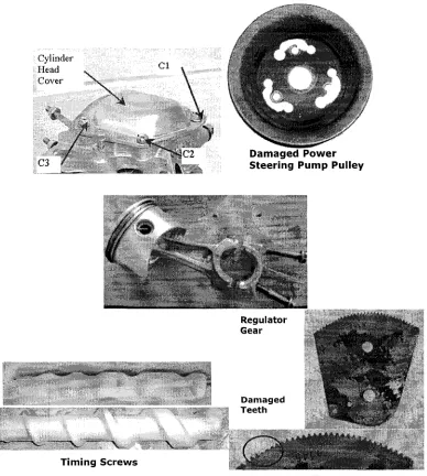
Using the IDEFO m odels as a platform and the sample com ponents show n in Figure 1-6 and Table 1-5 as test pieces, a reverse engineering fram ew ork that integrates reverse and forw ard engineering techniques was developed. T he fram ew ork consists o f structured guidelines to obtain the relevant design inform ation at different perspectives. This includes providing specific inform ation o f the context o f the com ponent’s application, its operating environm ent, the com p o n en t and feature functions, inform ation on feature patterns and relationships, and instructions for geom etry reconstruction. T he design recovery fram ew ork is presented in C hapter 3, using a cylinder valve cover and a pow er steering pum p pulley to illustrate the m ethodology.
1?}C2 D am aged Pow er S teerin g Pump Pulley
Regulator Gear
D am aged T e e th
T im ing S c r e w s
Figure 1-6: Valve Cover, Pow er Steering Pum p Pulley, Connecting Rod, Timing Screws, and Regulator G ear
Table 1-5: Test C om ponents Summary
C o m p o n en t M anufacturing P rocess C o m m en ts
Cylinder Valve Cover Stamped
3D thin walled part, bent and distorted gasket sealing face
Power Steering Pump
Pulley Rolled, Drawn, Punched Rotary part with damage on the flange face
Connecting Rod Die Cast and Machined
3D axially symmetric part with draft and ejector pin bosses, ground o ff runners, gates and trimmed flash
Timing Screws Machined
3D part with variable pitch screw used to control motion
In C hapter 5, it is show n how the fram ew ork can be directly associated w ith form al engineering design tools in order to assess the design and provide a foundation for design im provem ents. T he design recovery fram ew ork is linked to the Axiom atic D esign m ethodology [Suh, 2001] and the product complexity assessm ent m etrics developed by ElM araghy and U rbanic [2004, 2003]. T he connecting ro d and tim ing screws are used as case studies to illustrate this.
C h a p t e r 2
R E L A T E D R E V E R S E E N G I N E E R IN G R E S E A R C H
2 REVERSE GEOMETRIC MODELLING
This chapter focuses o n point cloud data collection techniques and surface reconstruction, w hich in essence is n o t reverse engineering, b u t reverse geom etric modelling. Significant research has been perform ed on scanning systems that quickly collect p o in t cloud data corresponding to the surface o f the part. W hen creating a C A D m odel from these techniques, there are four m ajor steps: data acquisition, pre-processing, surface construction and creating the final CA D m odel (Figure 2-1).
Data Capture
Pre-Processing
i t • Filtering • Mesh Creation • Mesh
Manipulation
Patches: • type • Resolution • C on tin u ity,...
Figure 2-1: Reverse Geometric Modelling
Scanned data m ust be filtered to reduce noise and the decrease the num ber o f data points to im prove processing times. Sophisticated algorithms are utilized to generate a surface m odel from the filtered data directly from the points [Fischer and Park, 1998], |Lim aiem and ElM araghy, H ., 1999], [Krause, 2003], [Phillipe et al, 1998] or an interm ediary m esh is constructed and the surface is constructed from the m esh [Attene and Spagnuolo, 2000], [Azernikov and Fischer, 2003], [Azemikov and Fischer, 2004], [Barhak and Fischer, 2001], [Barhak and Fischer, 2002], [Benko et al, 2002], [Benko et al, 2001], [Bernardini et al, 1999],
[Fischer and Park, 1998], [Gao et al, 2004], [Huang et al, 2003], [Karbacher, and Hausler, 1998], [Page, 2003], [Steiner and Fischer, 2001], [Volodine et al, 2003], [Zhang et al, 2002]. A brief description o f data collection techniques, filtering, m eshing, surface reconstruction and m easurem ent related sources o f error follow.
2.1 SCANNING SYSTEMS
T h e geom etry acquisition is a digitization process whereby a scanning system is used to produce a set o f unsorted 3D data points, called a po in t cloud. T here are several data acquisition scanners, w hich can be categorized as tactile or rem ote (Figure 2-2). T h e scanners are m o u n ted on a coordinate m easuring m achine (CMM), a ro b o t or o n a special purpose m achine. A CMM is a 5-axis robot, consisting o f three translational axes for X , Y and Z m otions, and two rotary motions: around thejy-axis ( A ) and around the y-axis (B) on the wrist u p o n w hich the m easuring devices (physical contact probes, scanners) are m ounted.
CT or MRI Optical Based
CMM Volume
Surface Robotic
Arm Remote
Techniques
Tactile Techniques Reverse Geometric
Modelling
Systems Laser Based Systems Acoustic Based Systems
Systems Touch
trigger probe
Drag probe Hard Probe
I 1
y
XA x is
m o t i o n
-180 ° i 180
105 °
A rotation B rotation
T here are three m ain types o f tactile sensors:
(i) to u ch trigger probes m ounted on a CMM, w hich tem porarily contact w ith the m easured surface at a specified point,
(ii) hard probes m ounted on a ro b o t or C N C machine, w hich also tem porarily contact w ith the m easured surface at a specified point; and
(iii) analogue probes, w hich are dragged along the surface o f the artefact along a specified line.
T he geom etry and m aterial o f the com ponent to be m easured influences the stylus geom etry and material. T he probe m ust have the reach and shape to be able to access the features that are to be m easured w ithout com prom ising the process (i.e. shank interfering w ith an obstacle, accessing deep features, or determ ining tapped hole positions).
T h e stylus ball material influences the long-term accuracy o f scanning results. T h e ball m aterial can wear, or pick up material (adhesion wear) from the com ponents being m easured, w hich may be an issue w ith analogue probe scanning. B oth wear types result in perm anentiy changing the shape o f the stylus ball, w hich in turn com prom ises the accuracy o f the data. Ruby styli are good for general purpose applications, b u t silicon nitride is the best choice for alum inum , whereas zirconia is ideal for cast iron [Renishaw, 2004]
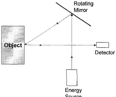
W ith rem ote non-contact sensing devices, light, sound or m agnetic devices are used to capture inform ation about the surface or volum e o f the artefact. Typically w ith rem ote sensors, large am ounts o f point data are collected quickly. T here are several m ethods w hich are briefly discussed here: stereovision using existing illumination (passive triangulation), active triangulation (light is projected onto the artefact), ranging, structured light (Moire fringe), image analysis, com puter tom ography (CT scan), echography (sonar), and m agnetic resonance imaging (MRI).
Triangulation techniques allow the depth to be inferred (Figure 2-3). G iven I I , L , and A , the height o f the object D is determ ined by:
L
Position-sensiiivi
phofodetector /
- Laser
Light sp o t
Figure 2-3: Laser Triangulation for Measuring D im ension D [Feng, 2002]
W ith stereovision techniques, a camera w ith two lenses or m ultiple cameras are used to obtain inform ation necessary to infer depth by corresponding the features in b o th stereo images. Passive triangulation may lead to ambiguous results. T he correspondence problem is ill-posed, and therefore, leads to either sparse distance m easurem ents or erroneous results b ased o n m ism atches. Additionally, the stereovision techniques are susceptible to spectral highlights, harsh shadows, and surface inter-reflections [Page et al, 2003].
W ith active triangulation, a light source such as a laser (for a “sheet o f light” the beam is expanded by a special lens) and a charge couple device (CCD) cam era are used to collect the p o in t cloud data. T he laser beam is projected onto a surface, w hich is observed by the cam era at a different angle (Figure 2-4). By analysing the distortions created by the target’s topology using simple trigonom etric rules, the 3D position o f the points on the surface can be determined.
4 taser Ccwitva A .
W) O verview ■ i i u p . (b« Laser line a s’‘seen" by the laser, tu 1 1 * 0 1 linear w-en l*\ the camera.
Figure 2-4: Images Seen by the Laser and Camera for Active Triangulation [Teutsch, 2003]
Structured light techniques involve projecting patterns o f light (grid, stripes, ellipses) o n to the surface o f the artefact. A n interference pattern such as a M oire fringe is projected on to the surface producing distorted contour lines (Figure 2-5), w hich are captured by a C C D camera and subsequently analysed. W ith a M oire fringe, a grating is projected onto an object and an image is form ed w ith respect to a reference grating. K now ledge o f the reference grating, m aster grating, the position o f the camera and projector in space is required so th at the depth can be calculated by triangulation [Clarke et al, 1993]. T h e distance betw een the lines is proportional to the height o f the points o f interest on the surface.
Figure 2-5: Moire Fringe [Ypsilos, 2004] and Image
D istorting the Fringe [Bujakiewicz e t al, 2004]

![Figure 2-8: Single Slice Tomogram of a Cylinder Head [Flisch et al, 1999]](https://thumb-us.123doks.com/thumbv2/123dok_us/1482432.1181391/42.614.184.470.67.277/figure-single-slice-tomogram-cylinder-head-flisch-et.webp)