IJEDR1602313
International Journal of Engineering Development and Research (www.ijedr.org)1
Damage Detection of Simply Supported Beam by
Residual Force Method
B.Malar Nivetha1, Dr. S.Parivallal2, Dr.D.Suji3 1P.G Student, Adithya Institute of technology, Coimbatore.
2Senior Principal Scientist, CSIR-Structural Engineering Research Centre, Chennai 3HOD and Professor, Adithya Institute of Technology, Coimbatore
Abstract - Structural health monitoring (SHM) involves the observation of a structure or mechanical system over time using periodical measurements, the extraction of damage-sensitive features from these measurements and the statistical analysis of these features to determine the current state of system health. Modal frequencies and mode shapes are the most popular parameters used in damage identification. The basic idea of these techniques is that modal parameters are functions of physical properties of structure (mass, damping and stiffness). Therefore, changes in physical properties will cause changes in modal properties. Structural damage identification based on residual force method is studied in this paper. Residual modal force is used as an indicator of structural damage. This residual modal force is caused by changes in structural parameters due to the occurrence of damage. A simulated simply supported beam with assumed damage scenario is used to demonstrate the approach. Numerical study has been carried out on a beam of size 230mmx300mm and of length 3000mm. The beam is subjected to different simulated damage scenarios i.e., single damage, double damage and multi damage and degree of damage. If a structural member is cracked, the crack will decrease the stiffness and thereby decrease the eigen frequencies of the structure hence here, damage is introduced as the reduction in stiffness by altering the young’s modulus. The beam is modelled and dynamic characteristics such as frequency and mode shapes are calculated through finite element software ABAQUS. By using residual force vector the damage is identified.
Keywords - structural health monitoring, residual force method, Eigen frequencies, dynamic characteristics.
1. Introduction:
Occurrence of damage in existing civil structures causes reduction in their load carrying capacity and might end-up with catastrophic failure if not maintained at early stages. Inaccessibility of portions of structures, presence of unseen cracks, as well as material deterioration of some parts of the structure can lead to whole structure failure or some of its elements. Early prediction of this damage could help in increasing their life time and prevent unexpected modes of failure. Therefore, health monitoring of vital structures by means of reliable non-destructive damage detection tools is crucial to maintain safety and integrity of these structures.
The fundamental idea for the vibration-based damage identification is that the damage-induced changes in the physical properties such as mass, damping, and stiffness will cause detectable changes in modal properties (e.g., natural frequencies, modal damping, and mode shapes). For instance, reductions in stiffness result from the onset of the cracks. Therefore, it is intuitive that damage can be identified by analyzing the changes in vibration features of the structure. Residual modal force is used as an indicator of structural damage. This residual modal force is caused by changes in structural parameters due to the occurrence of damage.
IJEDR1602313
International Journal of Engineering Development and Research (www.ijedr.org)1785
purpose of this work is to use the residual force method to detect structural damages successfully in beam. Also, to verify t he efficiency of the developed technique on different structures with different damage ratios.2.0. Residual modal force:
Assuming that the mass matrix is unchanged before and after damage occurs and damage causes only a reduction in the stiffness of the elements. Without considering the influence of damping, under free vibration a characteristic equation can be written as
( K d − λdi M ) φdi = 0 (1) Kd = K u − ∆K (2)
Where, M is the mass matrix, Ku and Kd are the n-n stiffness matrices associated with the undamaged and damaged states, ∆K is the change in the stiffness matrix as a result of damage, λdi and φdi are the ith eigenvalue (the square of the damaged natural frequency) and the corresponding eigenvector (mode shape) for the damaged structure, respectively. Especially, all matrices mentioned above are real symmetric matrices.
Substituting Eqn (2) into Eqn (1), yields
( Ku − λdi M ) φdi = ∆Kφdi (3)
Because the left-hand side of Eqn (3) is known, we define a residual force vector for the ith mode as ri = ∆Kφdi (4)
Then, Eqn (3) can be rewritten as
( Ku − λdi M )φdi = ri (5)
From the right-hand side of Eqn (4), we know that ri will be zero when structure is undamaged. In other words, there is no change in structural stiffness and K equals to zero in this case. Conversely, the elements in ri with nonzero values are associated with damage locations. Therefore, by identifying nonzero values in residual force vectors, one can detect the damage sites in the structure
The residual modal forces are basically caused by changes in structural parameters due to the occurrence of damage. If the relationship between the residual modal force and the change in structural parameters can be found, the information provided by the residual modal force can then be used to determine the physical parameters at the damaged site.
2.1. Element damage index and damage equation:
If the changes of the dynamic system characteristics are used for structural damage identification, it is necessary to have the disposal of an adequate numerical model that is able to predict the observed changes. The relation between the reshaped residual force and the reshaped damaged modal stiffness matrix is:
S R* (6)
S = [
𝐾1𝜑𝑑1 𝐾2𝜑𝑑1 𝐾N𝜑𝑑1
𝐾1𝜑 𝑑2 𝐾2𝜑𝑑2 𝐾𝑁𝜑𝑑2
𝐾1𝜑 𝑑𝑚 𝐾2𝜑𝑑m 𝐾𝑁𝜑𝑑𝑚
] (7)
Where α is the damage ratios vector which contains the damage ratio in each element of the structure (αi) as follows:
α = α1 α2 α3 αne
Where R is the jth residual force vector. A residual force square matrix R is constructed with size (nxn) as n is the number of degrees of freedom, where each column in this matrix represents the vector (rj) as follows:
R r1 r2 rn (9)
The residual force matrix R is reshaped to be a single vector which is called the reshaped residual force R*.
IJEDR1602313
International Journal of Engineering Development and Research (www.ijedr.org)1786
Where, subscript m indicates the number of measured mode shapes. Eqn (8) indicates the relationship between the damage coefficient and the residual force vector at the elemental level.The element damage ratios can be obtained from the previous equation as follows:
α = S+ R* (11) Where S+ is the pseudo-inverse of the matrix S. 2.2. Element Stiffness Matrix:
Figure1. Eight node brick element
Stiffness matrix of 3-D solid isoparametric elements is formulated by the following relations.
∭+1+1+1[𝐵]𝑇
−1−1−1 [𝐷][𝐵] dξdηdζ |J|
The size of the constitutive matrix [D] for solid element will be 6 × 6 .For eight node brick element, the size of stiffness matrix will become 24 × 24 as number of nodes in one element is 8 and the degrees of freedom at each node is 3.
3. Numerical study:
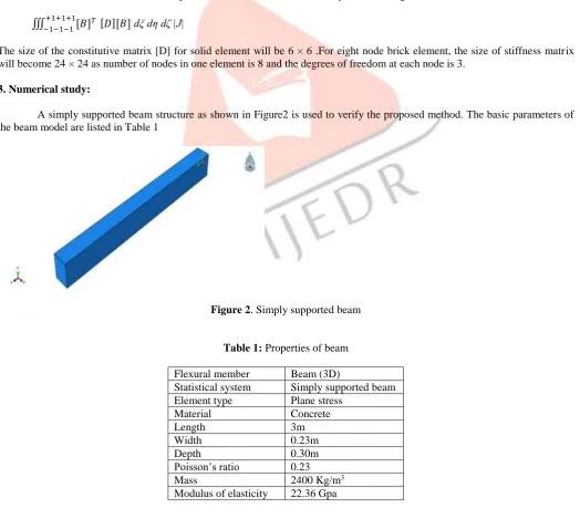
A simply supported beam structure as shown in Figure2 is used to verify the proposed method. The basic parameters of the beam model are listed in Table 1
Figure 2. Simply supported beam
Table 1: Properties of beam Flexural member Beam (3D)
Statistical system Simply supported beam Element type Plane stress
Material Concrete
Length 3m
Width 0.23m
Depth 0.30m
Poisson’s ratio 0.23
Mass 2400 Kg/m3
IJEDR1602313
International Journal of Engineering Development and Research (www.ijedr.org)1787
The finite element model of the beam is modelled in ABAQUS software. The beam is equally divided into 40 elements with the size of each element as 75mm. The element type used for the analysis is C3D8R an eight noded brick element.In order to study the damage detection by residual force method three damage scenarios are considered. Damage is introduced as the reduction in stiffness by altering the young’s modulus. The damage cases are as follows
Case 1: single damage Damage location-21st element Damage magnitude: 50% Case 2: Double damage
Damage location-13th and 21st element
Damage magnitude: 50% and 25% in the element 13 and 21 respectively. Case 3: Multi damage
Damage location-6, 18 and 29th element
Damage magnitude: 50%, 25% and 75% in the element 6, 18 and 29 respectively 3.1 Natural frequency and Mode shapes calculation
Free vibration analysis is carried out for the undamaged and the damage model. From the analysis, the natural frequencies of the undamaged beam and damage cases obtained using ABAQUS FEA Software and is listed in Table.2.
Table 2: Frequency variation Mode
Frequencies (Hz)
Undamaged Case 1 Case 2 Case 3
1 58.818 55.881 57.304 55.589
2 135.35 135.16 119.72 111.03
3 344.71 299.84 335.15 306.76
4 529.35 521.45 472.84 449.84
4. Result and discussion:
4.1 Single damaged element:
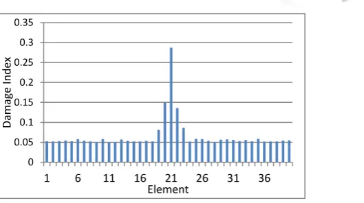
For Single damage case, damage is created in element 21 with 50% reduction in Young’s modulus. Free vibration analysis was carried out. From the analysis, mode shape and corresponding frequency of vibration are obtained. Residual force vector is calculated for each element from the stiffness matrix, mass matrix, frequency of vibration and eigen vector with the Eqn.5. Damage index is calculated from the Eqn.11. The calculations are carried out in the MATLAB. By singular value decomposition (SVD) method the damage index is identified for each element. Damage index is calculated for each mode to examine the accuracy of damage detection and the results are found satisfactory in mode 3 because it undergoes a significant change in frequency and Eigen vector. Figure 4 shows the damage index for each element for mode 3. From the figure the damaged element is identified as 21st element. The damage created in the modal is at element 21. Hence the residual force vector method identifies the damage element created.
Figure 4 Damage index of single damage element 4.2 Double damage case
For double damage case, damage is created in element 13 and 32 with 50% and 25% reduction in Young’s modulus respectively. Free vibration analysis was carried out. From the analysis, mode shape and corresponding frequency of vibration are obtained. Residual force vector is calculated for each element. Damage index is calculated for each mode to examine the accuracy of damage detection. Figure 5 shows the damage index for each element for mode 4. From the figure the damaged
0 0.05 0.1 0.15 0.2 0.25 0.3 0.35
1 6 11 16 21 26 31 36
Damag
e In
d
ex
IJEDR1602313
International Journal of Engineering Development and Research (www.ijedr.org)1788
element is identified as 13th and 32nd element. The damage created in the modal is at element 13 and 32. The residual force vector method identified the damage element created.Figure 5 Damage index of double damage element 4.3 Multi damaged element:
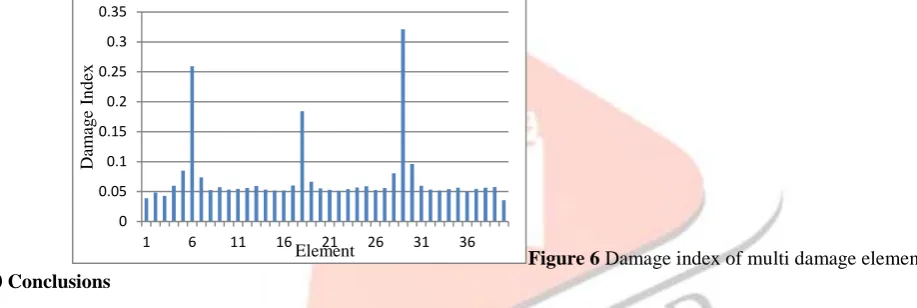
Damage is created in element 6, 18 and 29 with 50%, 25% and 75% reduction in Young’s modulus respectively for multi damage case. Free vibration analysis was carried out. From the analysis mode shape and corresponding frequency of vibration are obtained. Residual force vector is calculated for each element. Figure 6 shows the damage index for each element for mode 4. From the figure the damaged element is identified as 6th, 18th and 29th element. The damage created in the modal is at element 6, 18 and 29. The damage identified from residual force method matches with the damaged created in the model.
Figure 6 Damage index of multi damage element 5.0 Conclusions
A residual modal force based damage detection method is used to locate damage is presented. The residual modal forces are basically caused by changes in structural parameters due to the occurrence of damage. If the relationship between the residual modal force and the change in structural parameters can be found, the information provided by the residual modal force can then be used to determine the physical parameters at the damaged site. The residual force method is used to locate the suspected damaged elements in a simply supported beam model.
A simply supported beam is discretized into 40 equal elements with each element size as 75mm. Damages were introduced as the reduction in stiffness by altering the young’s modulus. The beam is subjected to different simulated damage scenarios i.e., single damage, double damage and multi damage and different degree of damage. From the free vibration analysis in ABAQUS software mode shapes and corresponding frequency are calculated. Residual force vector is calculated for each element from the stiffness matrix, mass matrix, frequency of vibration and eigen vector. By singular value decomposition (SVD) method the damage index of each element is identified.
Based on the study the following conclusions are arrived
There is change in natural frequency and mode shape of the beam structure due to the presence of damage.
The change in frequency is less in first mode for the damaged and undamaged beam and as the number of mode increase there are more frequency changes.
The damage identified from residual force method matches with the damaged created in the model.
6. Acknowledgements:
This paper is published with the permission of the Director, CSIR-Structural Engineering Research Centre. The first Author is thankful to the Management of Adithya Institute of technology for permitting her to carry out the M.E project work reported in this paper at CSIR-SERC, Chennai.
7. References:
0 0.05 0.1 0.15 0.2 0.25 0.3
1 6 11 16 21 26 31 36
Da
m
ag
e
In
d
ex
Element
0 0.05 0.1 0.15 0.2 0.25 0.3 0.35
1 6 11 16 21 26 31 36
Da
m
ag
e
In
d
ex
IJEDR1602313
International Journal of Engineering Development and Research (www.ijedr.org)1789
[1].Atef Eraky, Alaa Saad , Ahmed M. Anwar, Ayman Abdo, ”Damage detection of plate-like structures based on residual force vector” Housing and Building National Research Center HBRC Journal(2015)[2].Jianhua Zhao and Ling Zhang,” A Method for Structural Damage Identification Using Residual Force Vector and Mode Shape Expansion” IEEE, pp. 945-949(2015).
[3].Kaushar H. Barad, D. S. Sharma, Vishal Vyas, ”Crack detection in cantilever beam by frequency based method”, Nirma University International Conference on Engineering (NUiCONE), pp.770-775, (2013).
[4].Z. Ismail, H. Abdul Razak, A.G. Abdul Rahman, Determination of damage location in RC beams using mode shape derivatives, Eng. Struct. 28 (11)pp.1566–1573 (2016).
[5]Q.W. Yang, J.K. Liu,” Structural damage identification based on residual force vector” Journal of Sound and Vibration 305, pp.298–307(2007)
[6]Baruh H., Rattan S., “Damage Detection in Flexible Structures.” Journal of Sound and Vibration, 166(1), pp.21-30, (1993). [7]D.C. Zimmerman, M. Kaouk, Structural damage detection using a minimum rank update theory, Journal of Vibration and Acoustics 116(2) pp.222–231 (2005).
[8]Q.W. Yang, J.K Liu (2007) “Structural damage identification based on residual force vector” Journal of Sound and Vibration 305 (2007) PP.298-307
[8] Ramanamurthy E.V.V. , Chandrasekaran K. (2008) “Damage detection in composite beam using numerical modal analysis”