Free-space optics mode-wavelength division multiplexing
system using LG modes based on decision feedback
equalization
Angela Amphawan1,2*, Alaan Ghazi1,3 and Aras Al-dawoodi,3 1
Optical Computing and Research Laboratory, School of Computing, Universiti Utara Malaysia, 06010 Sintok, Kedah, Malaysia 2
Research Laboratory of Electronics, Massachusetts Institute of Technology, 02139 Cambridge, Massachusetts, USA ³Computer Science Department, College of Science, Kirkuk University, 00964 Kirkuk, Iraq
Abstract. A free-space optics mode-wavelength division multiplexing (MWDM) system using Laguerre-Gaussian (LG) modes is designed using decision feedback equalization for controlling mode coupling and combating inter symbol interference so as to increase channel diversity. In this paper, a data rate of 24 Gbps is achieved for a FSO MWDM channel of 2.6 km in length using feedback equalization. Simulation results show significant improvement in eye diagrams and bit-error rates before and after decision feedback equalization.
1 Landscape
Free Space Optics (FSO), a license-free technology which offers higher bandwidth than conventional radio communications. It can be installed quickly at a lower cost compared to laying fiber optic cables [1]. Based on these advantages, FSO has emerged as a promising solution for the last mile bottleneck considering the scarcity of radio bandwidth despite various approaches for optimization of the radio spectrum [2, 3]. FSO also offers an alternative transmission medium to fiber optics for rural and geographically-challenged locations where cabling may be an issue [4].
With the tremendous growth in the Internet technology, the demand for higher bandwidth to support more applications and a larger number of subscribers is expected to continue escalating in the near future [5, 6]. Therefore, enhancing the capacity of FSO is necessary for high-speed transfer of a large amount of data. Currently, numerous techniques such as wavelength division multiplexing (WDM) [7], time division multiplexing (TDM) [8], and orthogonal frequency division multiplexing (OFDM) [9] have been employed in enhancing data transmission capacity in FSO systems.
Nevertheless, as a result of the exponential growth in data bandwidth, existing multiplexing strategies may not be sufficient to accommodate future traffic growth. An emerging multiplexing scheme, known as mode division multiplexing (MDM), has been used to transport independent channels simultaneously using eigenmodes [10]. In MDM, eigenmodes are used in MDM to drive the propagation of a number of channels on different modes generated by various mechanisms such as photonic crystal fibers [11], optical signal processing [12, 13], few mode fiber [9, 14], modal decomposition methods [15, 16], laser designs [17, 18] and spatial light modulators [19, 20]. MDM has been used for switching [21] and for multiplexing [10] in FSO systems.
Furthermore, in order to make FSO more feasible in respect to high capacity performance, photonic and electronic equalization schemes need to be integrated and explored, which will scale FSO better than through being duplicated using simple hardware [25]. In this paper, we explicate an initiative that uses decision feedback equalization (DFE) for MWDM using LG modes from a vertical cavity surface-emitting laser (VCSEL) as data carriers over FSO. The analyses of the MWDM system performance before and after the DFE will be analyzed.
In the remaining part of this paper, Section 2 reports on the MWDM modelling using LG modes over FSO. Section 3 discusses the simulation results of the MWDM system and the discussion is concluded in Section 4.
2 Simulation of FSO MWDM System
A FSO MWDM system of seven Laguerre-Gaussian (LG) modes based on DFE has been simulated in OptSim [26] and exhibited illustratively in Fig. 1. The FSO MWDM system consists of three parts; transmitter, FSO channel, and receiver. The input signal is generated using a pseudo-random binary sequence (PRBS) from the data generator at 3 Gbps. which is modulated to non-return-to-zero (NRZ) sequence, and is connected to a seven-segmented spatial vertical cavity surface emitting laser array with each segment represented as SpVCSELs. The SpVCSELs operate on two wavelengths; 1550.12 nm and 1551.92 nm and seven LG modes; LG 0 0, LG 0
1, LG 0 2, LG 1 1, LG 1 2, LG 2 0 and LG 2 1. Each SpVCSELs has an array emitting one LG mode on two wavelengths. Given 3 Gbps is transmitted by each mode and each wavelength. Thus, with 7 modes and 2 wavelengths per mode, the total data rate is 7 x 2 x 3Gbps = 42 Gbps. The FSO channel is 2.6 km long.
The FSO transmitter and receiver aperture is set to 20 cm, beam divergence is 1 µrad, and laser power is 0 dBm and based on clear weather conditions. After FSO, the seven receivers were used to retrieve the signals from FSO.
The main objective of decision feedback equalization is to compensate the ISI. The DFE comprises of feed-forward filter and feedback filter as seen in Fig. 2. The first part of DFE is a linear filter (feed-forward filter). A Linear filter was set as the parameter using tap number 9. The other part of DFE is a nonlinear filter (feedback filter) using tap 12 with MMSE-optimization. The optimization of MMSE is operated between the actual data and the target data, based on the error of MMSE will update the weight of tap filter to get a better result. Moreover, the performance of eye diagram and BER were analyzed for the LG modes before and after feedback filter. The main objective of decision feedback equalization is to enhance the signal received from the transmitted signals and reduce ISI. The results will be discussed in the next section.
Fig. 1. FSO MWDM system in conjunction with decision feedback equalization (DFE).
Fig. 2. Feed forward and feedback taps in DFE at the receiver
3 Simulation Results
Significant results were discovered from the BER and eye diagram upon application of DFE to improve the bandwidth of the FSO system.
Fig. 3 represent the eye diagrams of the first four channels using LG 0 0, LG 0 1, LG 0 2 and LG 1 0 modes before and after DFE. Fig. 4 represent the eye diagrams of the first four channels using LG 1 1, LG 2
0 and
LG 2 1 modes before and after DFE. Fig. 3 and Fig. 4 illustrate that the eye openings for all channels on the seven LG modes have been widened and jitter is reduced.
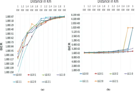
Another performance metric is the BER. The average values for BER prior to DFE and with DFE for distances between 1 km and 3 km are represented in Fig, 5(a, b). Meanwhile, the BER values for LG mode (0 0) at 1 km is 1.71 x 10⁻² before DFE (as seen in Figure 5(a) and Figure 5(b)). After DFE, it reaches up to
9.28 x 10⁻¹¹. Meanwhile, at 2 km, the BER is 1.63 x 10⁻² before DFE and after DFE, the BER is reduced to 1.10 x 10⁻¹². Further, LG (0 0) at 2.6 km is 1.84 x 10⁻² before DFE and after DFE it yields to 3.92 x 10⁻¹⁰ Also, LG (2 0) mode in Figure 5(a, b) show the BER values at 1 km is 1.71 x 10⁻² before DFE and after DFE, the BER improves to 2.87 x 10-103. At 2 2 km, the BER is x 10-2 before DFE and after DFE, it decreases to 9.03 x 10⁻²⁵. Meanwhile, the BER at 2.6 km is 2.31 x 10⁻² without DFE and with DFE, it is enhanced to 5.43 x 10⁻¹².
Additionally, Fig. 5(a, b) shows the BER for LG 2 1. At 1 km, it is 1.79 x 10⁻² before DFE and after DFE, the BER improves significantly to 8.44 x 10-135. At 2.6 km, it is 2.04 x 10⁻² before DFE and after DFE it becomes 3.84 x 10⁻¹⁷. For LG (2 1), at 2.6 km it is 4.62 x 10⁻¹² before feedback equalization and after feedback equalization it becomes 3.92 x 10⁻¹⁰. The results of the BER values have been enhanced after using DFE and after increasing the distance, the BER increases as seen in Figure (a, b). The maximum distance attainable with DFE is 2.6 km with acceptable BER.
Fig. 4. Effect of DFE on eye diagrams for last three channels on LG 1 1, LG 2 0 and LG 2 1 modes over 2.6 km FSO: (a) LG 1 1 without DFE (b) LG 1 1 with DFE (c) LG 2 0 without DFE (d) LG 2 0 with DFE (e) LG 2 1 without DFE (f) LG 2 1 with DFE
(a) (b)
Fig. 4. Effect of DFE on eye diagrams for last three channels on LG 1 1, LG 2 0 and LG 2 1 modes over 2.6 km FSO: (a) LG 1 1 without DFE (b) LG 1 1 with DFE (c) LG 2 0 without DFE (d) LG 2 0 with DFE (e) LG 2 1 without DFE (f) LG 2 1 with DFE
(a) (b)
Fig. 5. BER of seven LG modes (a) without DFE (b) after DFE
4 Conclusion
Simulation results demonstrate that with employment of DFE, eye diagrams and BERs for a FSO MWDM system over varying distances using LG modes have been improved. LG modes are successfully recovered at the receiver and 24 Gbps data transmission over 2.6 km has been attained.
References
1 Zabidi, S.A., et al., Int. Conf. on Comp. and Comm. Eng. (ICCCE) , Kuala Lumpur, Malaysia, pp. 1-5, (2010). 2 Liu, Z.Li, C.: Wireless Networks, , 23, 2, pp. 453-466.
(2017).
3 Amphawan, A., Omar, M.N. & Din, R. J Wireless Com Network 2012, 356, (2012)
.4 Enayati, S.Saeedi, H., IEEE Comm. Let., 20, (9), pp. 1824-1827.(2016).
5 Cisco, Cisco Visual Networking Index: Forecast and Methodology, 2016-2021 (2017).
6 Nisar, K., et al.: Journal of Network and Computer Applications, 36, 2, pp. 933-948, (2013).
7 Shahidinejad, A., et al.: Reviews in Theoretical Science, 2, 3, pp. 201-210, (2014).
8 Wang, D., et al., Int. Soc. for Optics and Photonics, 2016, edn.), pp. 100201F-100201F-100209, (2016). 9 Amphawan, A., et al., J. of the Eur. Opt. Soc. Europe,
9, (2014).
10 Amphawan, A., et al., IEEE Int. Coll. on Signal Proc. and its Applications (CSPA), pp. 145 - 149,( 2015). 11 Amphawan, A., et al.: J. Mod. Opt., 2013, 60, 20, pp.
1675-1683, (2013).
12 Arik, S.O., et al., IEEE Signal Processing Magazine, 2014, 31, 2, pp. 25-34, (2014).
13 Amphawan, A., et al., Journal of Modern Optics, 2012, 59, 20, pp. 1745-1752, (2012).
14 Tsekrekos, C.P.Syvridis, D., IEEE Photonics Technology Letters, , 24, 18, pp. 1638-1641, (2012). 15 Martin, L., et al., 7, pp. 44995, (2017).
16 Amphawan, A.O'Brien, D.,Proceed. IEEE International Conf. on Photonics (ICP2010), pp. 1-5. (2010). 17 Amphawan, A.Fazea, Y.: J. of the Eur. Opt. Soc.-Rapid
Publ., 12, 1, pp. 12, (2016).
18 Xueyuan, D., et al., Laser Physics, 25, 9, pp. 095102, (2015).
19 Carpenter, J.Wilkinson, T.D., J. of Lightw. Tech., 30, 12, pp. 1978-1984, (2012).
20 Amphawan, A., Optics express, , 19, 23, pp. 23085-23096, (2011).
21 Amphawan, A.Chaudhary, S.Int. Conf. on Optical and
Photonic Eng. (icOPEN 2015), Proc. of SPIE, 9524, (2015).
22 Wang, Z., et al., IEEE Photonics J., 1, 6, pp. 277-285, (2009).
23 Borah, D.K.Voelz, D.G., J of Lightw. Tech., 27, 18, pp. 3965-3973, (2009).
24 Chaudhary, S., et al.: Int. J. of Comp. App. , 93, 1, (2014).
25 Fazea, Y.Amphawan, J. of Opt. Comm, 37 ,4, pp.331-413. (2016).