Harmonic Interaction of Grid connected Renewable Energy System
with Fuzzy Logic controller
M . Sindhu & M . Shankar
M-Tech Student Scholar Department of Electrical & Electronics Engineering, KITS Engineering College, Ponnekal; Khammam (Dt), Telangana, India.
Assistant Professor Department of Electrical & Electronics Engineering, KITS Engineering College, Ponnekal; Khammam (Dt), Telangana, India
.
Abstract-In this paper FFT analysis of Grid connected Renewable system is presented. The increased power demand, the depletion of the fossil fuel resources and the growth of the environmental pollution has led the world to think seriously of other alternative sources of energy. So renewable energy resources (RES) are being connected to the distribution systems, mostly done by using power electronic converters. This paper deals with system integration and fuzzy logic based controller design for power management of a grid connected renewable energy source (RES). Due to the large use of power electronic devices, disturbances occur on the electrical supply network. These disturbances are due to non-linear devices. These will produce harmonics in the power system thereby causing equipment overheating, damage devices, EMI related problems etc. Active Power Filters (APF) is used to compensate the current harmonics and load unbalance. The proposed system consists of RES connected to the dc link of a grid-interfacing inverter. In this both load are connected that is non-linear load as well as unbalance load at distribution. Power electronic devices produces the unwanted harmonics to reduce this shunt active power filter is used. This new control concept is demonstrated with extensive MATLAB/Simulink .Finally the proposed scheme is implemented using conventional DC link controller and intelligence controller by using MATLAB/SIMULATION software to improve the power quality and the results are verified. This new control concept is demonstrated with extensive MATLAB/Simulink. Finally the proposed scheme is implemented using conventional PI controller and intelligence fuzzy controller.
Keywords: Harmonics, Power Quality, Non Linear Load, Distributed Generation, Fuzzy Logic Controller, 3 phase 4 wire Inverter.
I. INTRODUCTION
Renewable energy (RE) sources will become anincreasingly important part of power generation as thereserves of fossil fuels get closer to depletion. Among availableRE technologies, wind and solar energy sources are the mostpromising options, as they are omnipresent, freely available,and environmentally friendly.Distributed generation (DG) istermed as the integration of Renewable energy source (RES)at the distribution level [1]. The number of distributed generation(DG) units, including both renewable and nonrenewablesources, for small rural communities not connected to the gridand for small power
resources connected to the utilitynetwork has grown in the last years.
Electric Power quality is a term which has captured increasing attention in power engineering in therecent years, the measure of power quality depends upon the needs of the equipment that is being supplied.What is good power quality for an electric motor may not be good enough for a personal computer. Usually theterm power quality refers to maintaining a sinusoidal waveform of bus voltages at rated voltage and frequency [2-4].The waveform of electric power at generation stage is purely sinusoidal and free from any distortion. Many ofthe Power conversion and consumption equipment are also designed to function under pure sinusoidal voltagewaveforms. However, there are many devices that distort the waveform. These distortions may propagate allover the electrical network. In recent years, there has been an increased use of non-linear loads which hasresulted in an increased fraction of non-sinusoidal currents and voltages in Electric Network [6]. Classification ofpower quality areas may be made according to the source of the problem such as converters, magnetic circuitnon linearity, arc furnace or by the wave shape of the signal such as harmonics, flicker or by the frequencyspectrum (radio frequency interference) [7-8].
interfacingrenewable with the grid. The MATLAB/Simulink results are executed in this software and results are verified.
II. SYSTEM DESCRIPTION
The proposed system consists of RES connected to the dc link of a grid-interfacing inverter. It is shows that both load are connected that is non-linear load as well as unbalance load at distribution. Grid is connected to step down transformer with reduce voltage level for distribution side. For injecting Renewable energy to grid inverter that is power electronic devices is used. Power electronic devices produces the unwanted harmonics to reduce this shunt active power filter is used.
Shunt active power filter is used to compensate load current harmonics by injecting equal but opposite compensating current. In this project three phase four wire voltage source current controlled inverter is used. Generally three wire inverter is used but in this fourth terminal is used to compensate the neutral current. A voltage source inverter is convert renewable DC energy into Ac with required magnitude, phase angle and frequency. It also converts the DC voltage across storage devices into a set of three phase AC output voltages. It is also capable to generate or absorbs reactive power. If the output voltage of the VSC is greater than AC bus terminal voltages, is said to be in capacitive mode. So, it will compensate the reactive power through AC system. The type of power switch used is an IGBT in anti-parallel with a diode. The three phase four leg VSI is modeled in Simulink by using IGBT. The driving voltage across the inductance determine the maximum di/dt that can be achieved by the filter. A large valve of inductance is better for isolation from the power system and protection from transient distribution it also limit the ability of the active filter to cancel higher order harmonics.
III. CONTROL STRATEGY A. DC-Link Voltage and Power Control Operation
Due to the intermittent nature of RES, the generated power is of variable nature. The dc-link plays an important role in transferring this variable power from renewable energy source to the grid. RES are represented as current sources connected to the dc-link of a grid-interfacing inverter. The dc-capacitor decoupled the RES from grid and allows the independent control of inverter on either side of dc link. P1 to P8 switching signal of
inverter where P7 and P8 are multiplied with constant zero
to compensate the neutral current.
Fig.1:The control strategy of inverter B. Control of Grid Interfacing Inverter
The control diagram of grid- interfacing inverter for a 3-phase 4-wire system. The fourth leg of inverter is used to compensate the neutral current of load. The main aim of proposed approach is to regulate the power at PCC during:
1) PRES=0 ;
2) PRES<total load power (PL);
3) PRES>PL.
While performing the power management operation, the inverter is actively controlled in such a way that it always draws/ supplies fundamental active power from/ to the grid. If the load connected to the PCC is non-linear or unbalanced or the combination of both, the given control approach also compensates the harmonics, unbalance, and neutral current. The duty ratio of inverter switches are varied in a power cycle such that the combination of load and inverter injected power appears as balanced resistive load to the grid. The regulation of dc-link voltage carries the information regarding the exchange of active power in between renewable source and grid. Thus the output of dc-link voltage regulator results in an active current (IM). The multiplication of active current component (IM) with
unity grid voltage vector templates (UA, UB and UC)
generates the reference grid currents (IA*, IB*and IC*).
The reference grid neutral current (IN*) is set to zero,
being the instantaneous sum of balanced grid currents. The grid synchronizing angle (θ) obtained from phase locked loop (PLL) is used to generate unity vector as follows:
(1) (2)
(3) The actual dc-link voltage (VDC) is sensed and passed
presence of switching ripples on the dc-link voltage and in the generated reference current signals. The difference of this filtered dc-link voltage and reference dc-link voltage (VDC*) is given to a discrete-PI regulator to
maintain a constant dc-link voltage under varying generation and load conditions.
The dc-link voltage error VDC err(N) at nth sampling
instant is given as:
(4) The output of discrete-PI regulator at nth sampling instant is expressed as
(5) Where KP Vdc=10and KI Vdc= 0.05are proportional
and integral gains of dc-voltage regulator. The instantaneous values of reference three phase grid currents are computed as
(6) (7) (8) The neutral current, present if any, due to the loads connected to the neutral conductor should be compensated by forth leg of grid-interfacing inverter and thus should not be drawn from the grid. In other words, the reference current for the grid neutral current is considered as zero and can be expressed as:
(9) The reference grid currents (IA*, IB*, IC*and IN) are
compared with actual grid currents (IA, IB, IC and IN) to
compute the current errors as:
(10) (11) (12) (13) These current errors are given to hysteresis current controller. The hysteresis controller then generates the switching pulses (P1, P2, P3, P4, P5, P6, P7, and P8) for the
gate drives of grid-interfacing inverter.
The average model of 4-leg inverter can be obtained by the following state space equations:
(14)
(15)
(16)
(17)
(18) Where, VInvA, VInvB, VInvC and VInvN are the
three-phase ac switching voltages generated on theoutput terminal of inverter. These inverter output voltages can be modeled in terms of instantaneous dc bus voltage and switching pulses of the inverter as:
(19)
(20) (21) (22) Similarly the charging currents IInvAd, IInvBd, IInvCd and
IInvNd on dc bus due to the each leg of inverter can
beexpressed as:
(23) (24) (25) (26) The switching pattern of each IGBT inside inverter can be formulated on the basis of error between actual and reference current of inverter, which can be explained as: If IInvA< (IInvA*-hB), then upper switch will be OFF (P1=0)
and lower switch S4will be ON (P4=1) in the phase “A”
leg of inverter.
If IInvA> (IInvA*-hB), then upper switch will be ON (P1=1)
and lower switch S4will be OFF (P4=0) in the phase “a”
leg of inverter. Where hb is the width of hysteresis band.
Similarly switching pulses are derived for other three leg.
IV. FUZZY LOGIC CONTROLLER A. Fuzzy System
A fuzzy system is a system of variables that are associated using fuzzy logic. A fuzzy controller uses defined rules to control a fuzzy system based on the current values of input variables. Fuzzy system consists of three main parts: linguistic variables, membership functions and rules.
B. Linguistic Variables And Terms
linguistic variable has a range of expected values. The linguistic variables current temperature and desired temperature each might include the linguistic terms cold, moderate, and hot. The linguistic variable heater setting might include the linguistic terms off, low, and high.
C. Membership Functions
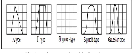
Membership functions are numerical functions corresponding to linguistic terms. A membership function represents the degree of membership of linguistic variables within their linguistic terms. The degree of membership is continuous between 0 and 1, where 0 is equal to 0% membership and 1 is equal to 100% membership. There are several types of membership functions available, namely, Λ-type (triangular shape), Π-type (trapezoidal shape), singleton-Π-type (vertical line shape), Sigmoid-type (wave shape), and Gaussian-type (bell shape) membership functions. The various membership functions are shown in Fig .2.
Fig.2: various membership functions
D. Fuzzy Inputs and Output
For example in terms of temperature there are two inputs and based on the combination of these inputs, the output is obtained. Each of these inputs has seven subsets. Input 1: Temperature Error
Input 2: Temperature Error Rate
Output : Fuzzy output to Heating rod or Pump
E. Subsets For Inputs And Output
Input 1(Temperature Error): Positive Big, Positive Medium, Positive Small, Zero, Negative Small, Negative Medium, Negative Big
Fig.3: membership function for error
Input 2 (Temperature Error Rate): Positive Big, Positive Medium, Positive Small, Zero, Negative Small, Negative Medium, Negative Big
Figure 4 displays the Edit Variable dialog box with all membershifunctions for the Error rate input variable.
Fig.4: membership function for error rate
Output: Positive Big, Positive Medium, Positive Small, Zero, Negative Small, Negative Medium, Negative Big
Fig.5: membership function for fuzzy output
F. The Rule Base Table
Rules describe, in words, the relationships between input and output linguistic variables based on their linguistic terms The total number N of possible rules for a fuzzy system is defined by the following equation:
(27) wherepn is the number of linguistic terms for the input linguistic variable n. If each input linguistic variable has the same number of linguistic terms, the total number N of possible rules is defined by the following equation:
(28) where p is the number of linguistic terms for each input linguistic variable and m is the number of input linguistic variables. Plotting a rule base in matrix form, is helpful for detecting inconsistencies, such as contradictory rules. However, plotting a rule base in matrix form is efficient only for small rule bases. Detecting inconsistencies in large rule bases is difficult. For fuzzy systems with numerous controller inputs, you can use cascading fuzzy systems to avoid large rule bases. The rule base table is shown below:
G. DEVELOPING FUZZY LOGICCONTROLLER
Fuzzy controllers are used to control fuzzy systems. Most traditional control algorithms require a mathematical model of the system you want to control. However, many physical systems are difficult or impossible to model mathematically. In addition, many processes are either nonlinear or too complex for you to control with traditional strategies. However, if you can describe a control strategy qualitatively, you can use fuzzy logic to create a fuzzy controller that emulates a heuristic rule of-thumb strategy. After a fuzzy controller fuzzifies the input values of a fuzzy system, the fuzzy controller uses the corresponding input linguistic terms and rule base to determine the resulting linguistic terms of the output linguistic variables. The block diagram of a fuzzy controller has been shown in Fig.6.
Fig.6: fuzzy logic block diagram H. FUZZIFICATION
Fuzzification is the process of associating crisp, or numerical, input values with the linguistic terms of the corresponding input linguistic variables. For example, a fuzzy controller might associate the temperature reading from a thermometer with the linguistic terms cold, moderate, and hot for the current temperature linguistic variable. Depending on the membership functions for the linguistic terms, the temperature value might correspond to one or more of the linguistic terms.
I. DEFUZZIFICATION
Defuzzification is the process of converting the degrees of membership of output linguistic variables within their linguistic terms into crisp numerical values. A fuzzy controller can use one of several mathematical methods to perform defuzzification.The most accuratedefuzzification method for a fuzzy controller varies based on the control application.
V. MATLAB/SIMULINK RESULTS
Fig.7. Matlab/simulink circuit for grid connected renewable energy at distribution level
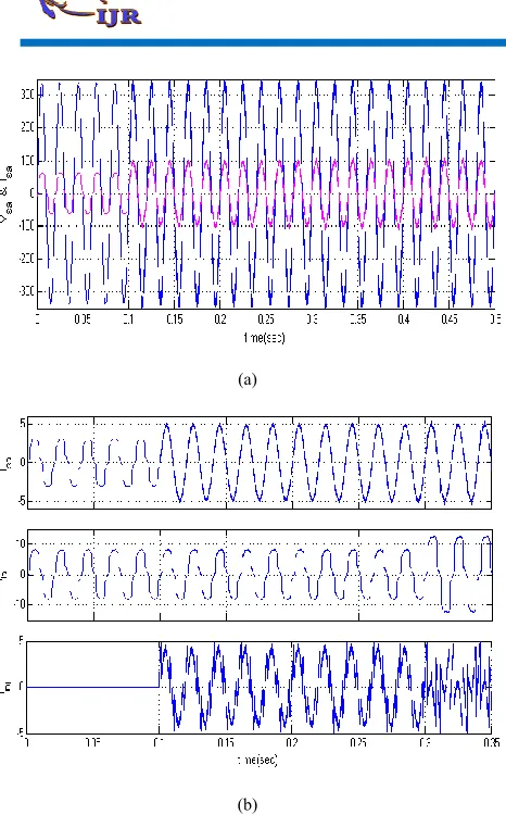
(a)
(b)
Fig.9. Simulation circuit of (a) Power factor (b) Source current waveforms
Fig.10. FFT analysis for THD using PI controller THD of source current
Fig 11.Matlab/simulink circuit for Fuzzy control circuit
Fig.12. FFT analysis for THD using THD of source current with fuzzy
VI. CONCLUSION
This paper has presented a novel control of an existing gridinterfacing inverter using conventional PI controller & fuzzy logic controller to improve the quality of power atPCC for a 3-phase 4-wire DG system. Proposed compensator is a flexible device which can operate in currentcontrol mode for compensating voltage variation, unbalance and reactive power and in voltage control mode asa voltage stabilizer. The simulation results show that the performance of converter system has been found to besatisfactory for improving the power quality at the consumer premises. By using conventional controller we getTHD value is 3.14%, but using the fuzzy logic controller THD value is 1.96%.
REFERENCES
[2] B. RUKESH KUMAR, J. AYYAPPA,” Grid Connected Renewable Energy System with Power Quality Improvement using Intelligent Controller,” International Journal of Scientific Engineering and Technology Research, ISSN 2319-8885, Vol.04, Issue.52, December-2015.
[3] S.Merlin Joys Mary, S.RajeshBabu, Dr.D.Prince Winston,”Fuzzy Logic Based Control of a Grid Connected Hybrid Renewable Energy Sources,” International Journal of Scientific & Engineering Research, Volume 5, Issue 4, April-2014 ISSN 2229-5518.
[4] J. KRISHNAVENI1, D. SRILATHA, “Simulation of Grid Connected Renewable Energy Sources with Power Quality Improvement Using Fuzzy Logic Controller,”ISSN 2319-8885 Vol.04,Issue.51, December-2015.
[5] M Archana , Y. C. V. kondaiah, “ Grid interfaceing inverter of renewable Energy source to improve the power quality in distribution system,” presented IJAREEIE conf. of Advanced research in Electrical, Electronics And InstruEngg, vol. 1,issue 5, nov 2012.
[6] V. Ilavarasi, C. Christober a. Rajan, “Power quality Improvementin Grid connected system using four leg VSI”, presented at IEEE conf. on Advances in engg, Science and Management, March, 2012.
[7] J. H. R. Enslin and P. J. M. Heskes, ―Harmonic interaction between a large number of distributed power inverters and the distribution network,IEEE Trans. Power Electron., vol. 19, no. 6, pp. 1586– 1593,Nov. 2004.
[8] P. Jintakosonwit, H. Fujita, H. Akagi, and S. Ogasawara, ―Implementation and performance of cooperative control of shunt active filters for harmonic damping throughout a power distribution system, IEEE Trans.Ind. Appl., vol. 39, no. 2, pp. 556–564, Mar./Apr. 2003
[9] O. Vodyakho T. Kim "Shunt active filter based on three-level inverter for 3-phase four-wire systems" lET proceedings on Power Electronics, Vol.2, No.3, pp. 216-226, Nov 2009.
[10] R.D.Patidar, S.P.Singh, "Hannonic, Reactive and Neutral current compensation in 3P4W Distribution System" International Conference on Engineering and Technology ICCET'09, Vol 2, pp 403 - 415, Singapore 2009.
[11] Joao afousonMauriaoAredes, Edson Watanabe, Julion Martins, "Shunt Active Filter for Power Quality Improvement", International Conference VIE 2000 - Electricity for sustainable Urban Development, Lisboa, Portugal , pp I -4, Nov 2000.
[12] M.EI-Habrouk, M. K. Darwish and P. Mehta, " The Active power filters: A review" IEEE proceedings on Electric power applications, Vol 147, No.5, pp 403 - 413, September 2000.