The Calibration of the Coupling Coefficients of the Mode-Selective
Coupler without the Single Mode Exciter
Lingna Yue*, Wenxiang Wang, Jin Xu, Hairong Yin, Guoqing Zhao, and Yanyu Wei
Abstract—As one of the important means in discriminating every mode in a high power microwave (HPM) multimode system, utilizing a mode-selective directional coupler to quantitatively analyze multi-modes and power measurement has been proposed. The first step of this method is to calibrate the coupling coefficients of each coupled mode in the HPM system. Moreover, the conventional calibrating method must make the corresponding single mode exciter or mode generator. In this manuscript, a different calibrating method is presented by measuring the output power from each output port of two back-to-back identical mode-selective couplers, including the backward wave power, then the coupling coefficients of each coupled mode can be calculated by combining and solving equations. In this way, it is not necessary to manufacture the single mode exciter or mode generator for each mode in the HPM system, and also to repeat iteration solution; therefore, this method is more precise, convenient, efficient, and has lower cost than the current other methods.
1. INTRODUCTION
The existence of multi-modes in the generation and transmission of high-power microwave (HPM) is unavoidable [1]. In order to determine the composition of output modes in HPM source, new modes generated in HPM transmission, mode discrimination of mode convertor, etc., it is necessary to discriminate and analyze those modes existing in HPM system. Many scholars have proposed methods of mode discrimination [2]. In these methods, Janzen and Sticked put forward a way using a mode-selective directional coupler to discriminate mode [3, 4]. Ref. [5] not only improves the theory on design of mode-selective directional coupler, but also points out that after calibrating coupling coefficients of the mode-selective coupler, it can qualitatively distinguish the modes transmitted in HPM system and determine the quantitative proportion of each mode, thus, the power of each mode can be calculated, so does the total power of HPM system.
When we use a mode-selective coupler to identify mode quantitatively and measure the HPM power, it must be done to calibrate the coupling coefficients of each coupled mode in it. The traditional calibrating method is to fabricate a single mode exciter or mode generator for every mode transmitted in the system. In principle, a mode converter can convertT E10mode in rectangular waveguide or TEM
mode in coaxial line into the expected mode [6–8]; however, for higher order modes, it will make the process of conversion very complex, the length of converters be extremely long, and the manufacture be profoundly difficult. We have presented the way to calibrate coupling coefficients of the mode-selective coupler in detail in [5], which obtains coupling coefficients of each mode directly without a single mode exciter or mode generator. However, the number of undetermined coupling coefficients is more than the number of independent equations obtained by measuring the power. Thus, the way for solving this problem is assuming an increment Δpof suppression of some unwanted modes to decrease the unknown
Received 15 May 2019, Accepted 30 September 2019, Scheduled 16 October 2019
* Corresponding author: Lingna Yue (email: [email protected]).
number. Then, it has to solve the independent equations by iterating and repeating this process until Δpis stable. Actually, Δp is chosen artificially, and the variation of Δpis random, so the requirement of making Δpfinally be constant is not easy to achieve. It may spend too much time to obtain reliable results.
This paper will improve the calibration of coupling coefficients based on the method proposed in [5], that is, single mode exciter of every mode needs not be considered, and the backward wave in the mode-selective coupler is taken into account, which results in that the number of independent equations obtained from measuring the output power of every coupling arm of the mode-selective coupler will be more than the number of unsolved coupling coefficients. Thus, all coupling coefficients can be achieved directly by solving the equations without the iteration.
2. EQUATIONS FOR CALIBRATION OF COUPLING COEFFICIENTS
2.1. Measuring System
Assuming that the main waveguide of mode-selective coupler is an overmoded circular waveguide in which modes 1, 2, and 3 exist, the sub-waveguide is aT E10 fundamental mode rectangular waveguide.
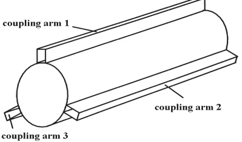
Three coupling arms are put on the main waveguide for measuring the composition and the power of modes 1, 2, and 3. The coupled mode of each coupling arm corresponds to modes 1, 2, and 3, respectively (as shown in Fig. 1). The number of each coupling arm is identical with its coupled mode number, i.e., the coupling arm 1 is corresponding to coupled mode 1 while modes 2 and 3 are unwanted modes in coupling arm 1, and so on.
Figure 1. The mode-selective coupler with three coupling arms, and the overmoded circular waveguide as main waveguide, the fundamental mode rectangular waveguide as sub-waveguide.
According to [4], coupling coefficients of variant modes are:
Cw+=−20 logA+w =Cw
Cu+=−20 logA+u =−20 log
A+wA
+ u A+w
=Cw+Pu
Cw−=−20 logA−w =−20 log
A+wA
−
u A+w
=Cw+dw
Cu−=−20 logA−u =−20 log
A+
u A−u A+u
=C+
u +du=Cw+Pu+du ⎫ ⎪ ⎪ ⎪ ⎪ ⎪ ⎪ ⎪ ⎪ ⎪ ⎬ ⎪ ⎪ ⎪ ⎪ ⎪ ⎪ ⎪ ⎪ ⎪ ⎭ (1)
where A is called the coupling intensity, which represents the relative amplitude of the T E10 mode
holes are given in [4]. From Eq. (1), it is obvious that coupling coefficients of all modes can be derived from the coupling coefficient of the coupled mode and suppression of the unwanted mode and the directivity.
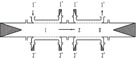
The measuring system is composed of two identical mode-selective couplers. Since their sizes are completely same, the characteristics of the two couplers are also completely same. Fig. 2 shows the sketch of the measuring system. The mode-selective coupler I serves as the signal input coupler, and the mode-selective couplerII acts as the measuring coupler. The ports of coupling arms of the couplers are indicated by 1+, 1−, 2+, 2−, 3+, 3−, and the third coupling arm is not given in Fig. 2. The matching load is terminated at two ends of the measuring system to prevent the reflection which may influence measuring accuracy. Based on the same reason, the ports of all coupling arms except the signal input and output ports for measurement should be terminated by matching load.
Figure 2. The schematic diagram of the measuring system for calibrating the coupling coefficients of the mode-selective coupler.
For convenience, kindicates mode numbers 1, 2, and 3;mrepresents the number of coupling arms of the input couplerI; andnrepresents the number of coupling arms of the measuring couplerII. Thus,
Cm,k=m expresses the coupling coefficient of mode k coupled into m coupling arm. According to the
definition of Cw in Eq. (1), k should be the coupled mode of m coupling arm, so k= m. Meanwhile,
because couplers I and II are identical so that if n = m, Cn,k=n = Cm,k=m, pm,k=m indicates the
suppression of the coupled mode to the unwanted mode coupled into m coupling arm. It is clear that only the modes with k=m are the unwanted modes. Moreover, on the one hand, when n=m and k
is the identical mode, pn,k=n = pm,k=m; on the other hand, dm,k represents the directivity of k mode
coupled into mcoupling arm, then,dn,k is equal todm,k under the same condition aspn,k=n=pm,k=m. Pk(m±) indicates the power ofk mode excited in main waveguide when the signal is input from port
m+ in +z direction or port m− in−z direction of the m coupling arm of the coupler I. In addition, Pk(m±, n±) represents the output power from port n± in ±z direction of the n coupling arm of the
couplerII when the transmission power is Pk(m±) ofk mode excited in main waveguide.
Since the transmission direction ofk mode in main waveguide is only +z direction and the power in −z direction absorbed by the matching load, the wave of kmode in −z direction does not exist at all. Then,k can represent wave k+ ofk mode in +zdirection.
2.2. The Calibration Equations of Coupling Coefficients, Suppressions and Directivities
There are eighteen undetermined values for the mode-selective coupler with three coupling arms, i.e., three coupling coefficients of coupled modesC1,1,C2,2, and C3,3; six suppressions of the coupled mode
to the unwanted modep1,2,p1,3,p2,1,p2,3,p3,1, and p3,2; three directivities of coupled modes d1,1,d2,2,
and d3,3; and six directivities of unwanted modesd1,2,d1,3,d2,1,d2,3,d3,1, and d3,2.
2.2.1. Input Signal Pin from m−
When signal Pin is input from the m− port, the forward wave of kmode excited in main waveguide is
Pk(m−) = 10−[(Cm,k=m+pm,k=m)/10]
Pin=Km,kPin Km,k = 10−[(Cm,k=m+pm,k=m)/10]
(2)
where m = 1,2,3; k= 1,2,3; pm,k = 0 when k = m. Eq. (2) includes nine equations for the variant
combination of m and k, i.e., P1(1−), P2(1−), P3(1−), P1(2−), P2(2−), P3(2−), P1(3−), P2(3−), and P3(3−).
(1)Pk(m−) is Output fromn+ Port
When powerPk(m−) of three modes (k= 1,2,3) in main waveguide is output from then+port of
coupling armnof coupler II, the total output power is
P(m−, n+) =
k=1,2,3
10−[(Cn,k=n+pn,k=n)/10]
Pk(m−) =
k=1,2,3
Kn,kKm,kPin
Kn,k = 10−[(Cn,k=n+pn,k=n)/10]
(3)
where m = 1,2,3; n= 1,2,3. Eq. (3) also includes nine equations for variant combinations of m and
n, i.e., P(1−,1+), P(1−,2+), P(1−,3+), P(2−,1+), P(2−,2+), P(2−,3+), P(3−,1+), P(3−,2+), and
P(3−,3+).
Couplers I and II are identical, thus, according to the reciprocity of passive component, when
m=n, the relationship is found
k=1,2,3
Kn,kKm,kPin=
k=1,2,3
Kn,kKm,kPin (n=m, m=n) (4)
i.e.,
P(n−, m+) =P(m−, n+) (5)
Equation (5) means that there are three sets of the nine equations from Eq. (3) which are equivalent, namely, P(1−,2+) = P(2−,1+), P(1−,3+) = P(3−,1+), P(2−,3+) = P(3−,2+). Consequently, only
six equations are independent for Eq. (3) in practice.
(2)Pk(m−) is Output fromn− Port
If powerPk(m−) of three modes (k= 1,2,3) excited in main waveguide is output from then−port
of coupling arm nof coupler II, the total output power will be
P(m−, n−) =
k=1,2,3
10−[(Cn,k=n++pn,k=n++dn,k)/10]Pk(m−) =
k=1,2,3
Rn,kKm,kPin
Rn,k= 10−[(Cn,k=n+pn,k=n+dn,k)/10]
(6)
where m= 1,2,3; n= 1,2,3. Eq. (6) also includes nine equations for different combinations ofm and
n, but these equations are independent except Eq. (3).
2.2.2. Input Signal Pin from m+
If signal Pin is input from them+ port, the backward wave excited by Pin in main waveguide is in +z
direction, and the forward wave is in−zdirection. Only the forward wave should be considered, so the power ofk mode in +z direction is
Pk(m+) = 10−[(Cm,k=m+pm,k=m+dm,k)/10]Pin=Rm,kPin Rm,k = 10−[(Cm,k=m+pm,k=m+dm,k)/10]
(7)
wherem= 1,2,3;k= 1,2,3;pm,k = 0 fork=m. Likewise, Eq. (7) includes nine equations for different combinations ofm and k.
If powerPk(m+) of the modes fork= 1,2,3 is output fromn+ port of coupling arm of coupler II
in +z direction, the total power will be
P(m+, n+) =
k=1,2,3
10−[(Cn,k=n++pn,k= n+)/10]Pk(m+) =
k=1,2,3
Kn,kRm,kPin (8)
Like Eqs. (4) and (5), we have
k=1,2,3
Kn,kRm,kPin=
k=1,2,3
Rn,kKm,kPin (n =m, m =n) (9)
that is
P(m+, n+) =P(m−, n−) (10)
It is thus clear that Eq. (8) is actually equivalent to Eq. (6), and just the orders of K and R are exchanged. Then, from Eq. (8), the number of the independent equations does not increase, but it provides another way to measure the output power.
(2)Pk(m+) Is Output fromn− Port
WhenPk(m+) exports from n− port, the output power is
P(m+, n−) =
k=1,2,3
10−[(Cn,k=n+pn,k=n+dn,k)/10]
Pk(m+) =
k=1,2,3
Rn,kRm,kPin (11)
wherem = 1,2,3;n= 1,2,3. Eq. (11) can derive nine equations for variant combinations of m and n. Similar to Eqs. (4) and (5), whenm=n, the expression is indicated as follows
k=1,2,3
Rn,kRm,kPin=
k=1,2,3
Rn,kRm,kPin (n=m, m=n) (12)
that is
P(n+, m−) =P(m+, n−) (13)
Equations (12) and (13) mean that P(1+,2−) = P(2+,1−), P(1+,3−) = P(3+,1−), P(2+,3−) =
P(3+,2−), thus, only six equations are independent among the nine equations expressed as Eq. (11).
3. CALIBRATION OF THE COUPLING COEFFICIENTS AND THE MEASUREMENT OF THE POWER
3.1. The Calibration of Every Mode
To sum up, there are twenty one independent equations from Eqs. (3), (5) (or (7)), and (9). Thus, eighteen unknown coupling coefficients, suppressions, and directivities can be solved using the measuring system shown as Fig. 2. There are two measuring methods, one utilizes a network analyzer to measure the ratio of input power to output power Pin/P(m±, n±), i.e., the value of |S21|2. The other uses a
high power source as the input signal and measuring the powerPin, then measuring the output power
P(m±, n±) by small-power powermeter. Thus,C, p, d can be obtained from Eqs. (3), (5) (or (7)), and (9).
Moreover, there are six input ports of the mode-selective couplerI (m±,m= 1,2,3) and six output ports of the coupler II (n±, n = 1,2,3) corresponding to each input port m. Thus, we can achieve thirty six output power values in which only twenty one measuring values are independent. The rest of measuring values should theoretically be repetitive with independent values according to the analysis in Section 2. C, p, d can be calibrated using eighteen values among the twenty one measuring values, and the other three measuring values may be used for verification.
In addition, because the input signal is fed from the coupling arm of the input coupler in which the operating mode isT E10mode, the signal mode exciter is not necessary for measured modes, which can
3.2. The Power Measurement
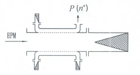
After C, p, and d are calibrated, the power of each mode and the total power can be obtained by measuring output power P(n±) in +z and −z directions of every coupling arm. The measurement system is given in Fig. 3. One calibrated mode-selective coupler is connected with the high power microwave transmission system. The high power microwave produced by HPM source is input from left port of the coupler, and its right port is connected to the operating load of the HPM system. The output power exported from coupling arm of the coupler is indicated by calibrated power indicator, usually, which is crystal detector and oscilloscope. To protect the crystal detector against the damage by large power, an attenuator may be inserted into the forestage of detector if necessary.
Figure 3. The schematic diagram of the power measuring system using the mode-selective coupler.
Once P(n±) have been measured, the total power of system is
P =
n=1,2,3 ⎡ ⎢ ⎢ ⎢ ⎣
P(n+)
k=1,2,3 Kn,k
+ P(n −)
k=1,2,3 Rn,k
⎤ ⎥ ⎥ ⎥
⎦ (14)
P(n±) is the total power of all three modes coupled intoncoupling arm, and consequently, the power of single mode cannot be achieved in principle. However, due to the selectivity of the coupling arm of mode-selective coupler, the power coupled into the coupling armnwill mostly be the power of coupled mode k = n of arm n. Thus, as an approximate, P(n±) can be considered as the power of coupled mode (k=n), and the power of unwanted modes (k=n) is neglected. The approximate power of each mode will be:
Pk=n= P
(n+)
Kn,k=n
+ P(n −)
Rn,k=n
(n= 1,2,3) (15)
If the suppression of coupled mode to unwanted mode, i.e., the pn,k=n, is large enough, Pk=n
obtained by Eq. (15) is quite precise.
It is obvious from Fig. 3 that the power measurement using the mode-selective coupler is an in-situ measurement, which does not affect the operation of HPM system. Then it is not necessary to disconnect the operating load from the system. Also it is a dynamic measurement, so the power variation entering into the system can be tested in real time.
4. CONCLUSION
REFERENCES
1. Benford, J., J. A. Swegle, and E. Schamiloglu, High Power Microwave, CRC press, part of Taylor &Francis Group LLC, 2006.
2. Wang, W., L. Yue, G. Zhao, et al., “Discrimination and analysis of microwave modes in high-power systems,”International Journal of Infrared and Millimeter Wave, Vol. 26, No. 2, 147–161, 2005. 3. Janzen, G. and H. Sticked, “Mode selective directional couplers for overmoded waveguide system,”
International Journal of Infrared and Millimeter Waves, Vol. 5, No. 7, 887–917, 1984.
4. Janzen, G. and H. Sticked, “Improved directional couplers for overmoded waveguide system,”
International Journal of Infrared and Millimeter Waves, Vol. 5, No. 10, 1405–1417, 1984.
5. Wang, W., Y. Gong, G. Yu, et al., “Mode discriminator based on mode-selective coupling,” IEEE Transactions on Microwave Theory and Techniques, Vol. 51, No. 1, 55–63, 2003.
6. Wang, W., L. Yue, et al., “Design of wide-wand mode discriminator based on mode-selective coupling,”International Journal of Electronics, Vol. 95, No. 2, 99–110, 2008.
7. Thumm, M. K. and W. Kaspaprek, “Passive high-power microwave components,” IEEE Transactions on Plasma Science, Vol. 30, No. 3, 755–786, 2002.