ADAPTIVE TURBO-EQUALIZER DESIGN FOR
MULTI-USER MOBILE COMMUNICATION CHANNEL
A. Kundu, B. K. Sarkar, and A. Chakrabarty
Kalpana Chawla Space Technology Cell (KCSTC)
Department of Electronics & Electrical Communication Engineering Indian Institute of Technology
Kharagpur-721 302, West Bengal, India
Abstract—Broadband single carrier modulated signals experience severe multipath distortion scrambling & ISI when propagating through physical medium. Correcting the distortion with channel equalization is the foremost task of the detector. Prior information about the transmitted signals in the form of channel decoder feedback can significantly enhance equalization accuracy. An algorithm that iteratively performs channel decoding and equalization with prior information is generally denoted turbo-equalizer. Turbo-Equalizer uses prior information & the principle of interference cancellation by MMSE criterion. Here we have tested Adaptive Turbo Equalization with least Mean Square Algorithm (LMS) & modified normalized LMS algorithm & Turbo-Decoding with a Log-Map. Consequently the Mean Square Error analysis, Stability analysis and convergence analysis are provided and its shown if the system is sparse, then the system will converge faster for a given total asymptotic MSE, though the choice of initialization is important. Here all the Implementation concepts have been verified in MATLAB platform and evaluation of the proposal is presented. The measurement for the performance is displayed as bit error rates (BER) in comparison to SNR of the Channel.
1. INTRODUCTION
14 Kundu, Sarkar, and Chakrabarty
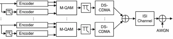
coding with turbo codes, modulation with QAM & spreading by CDMA. All the users signal are added on to the channel. Simplified model is shown in the Fig. 1. A usual assumption for wireless transmission channels is that AWGN occurs. Also ISI can be noticed originating from multiple paths scattering and delaying the signal. At the receiver , one of the best method for getting the information back from , often heavily scrambled & distorted received signal is to use turbo scheme [6–8], it can significantly improve the process of eliminating interference.
Figure 1. Turbo transmitter with ISI & AWGN in the channel.
The system shown in the Fig. 1 consists of a transmitter that uses a turbo code of the length K. the information data block denoted by xn for N users parallel, where vector x stands for a discrete time sequence; xn = xn[K] = {xn[0], xn[1], . . . , xn[K−1]} for users
decoder [6–9], producing the estimation of this user’s data ˆx1 and extrinsic information about bit probability for iterative use of the whole Turbo scheme Receiver. Fig. 1 shows Turbo scheme transmitter, source producing independent, identically distributed data sequence
xn of length K for all N users. Data blocks are encoded by a Turbo coder. For simulation we have used two binary convolutional coder having code rateRBCE = nkBCE
BCE = 1/2.
Here nBCE & kBCE are no of in and output of the convolutional coder respectively. Here two recursive systematic convolutional (RSC) codes with generator polynomial g1 = 23oct & g2 = 37oct are used. The generator polynomial notation is in octal corresponding binary values areg1 = 10011 &g2 = 11111. In delay tap it can be shown as
g1 =D+D3+D4 &g2 =D+D1+D2+D3+D4. A convolutional encoder produces an output that is (k+v)/RBCE bits longer than the input due to general action of the coder to add redundancy of rate RBCE and the additional tail of Rv
BCE bits. These come from
the last encoder back to an all zero state. This results a problem of ‘fractional rate loss’, a drop of the code rate (Real < RBCE) can be handled by either tail biting or truncation. One of the two Binary Convolutional Codes (BCEs’) is fed directly with the data sequence
xn. The other one with an interleaved version of it D (xn). D is the symbol for an interleaver, which defines a permutation of all bits, providing uncorrelated possible errors for the receiverC indicates the sign of de-interleaver.
2. M-ARY QAM MODULATION
Modulation is a mapping of binary data to a continuous time & valued signal. It presents an effective way of increasing the BW of a data transmission system. The basic idea is to map the input data to a constellation in the complex plane, thus using in phase & quadrature components i.e., employing in phase & quadrature carriers [12–14]. The RF transmit signal for use would be given by;
Sn(t) =R ∞ k=−∞
xQAM,n[k]g(t−kT)
ej2∗pi∗fc∗t
(1)
with
R{xQAM,n[k]}, I{xQAM,n[k]}∈
16 Kundu, Sarkar, and Chakrabarty
& AQ,n[k] are the amplitude levels calculated from the log2(M)/2 bits each of the in phase & quadrature component. From practical experience it has been seen that higher modulation order results in dense constellation, as the altogether available power is assumed to be restricted and the symbol position have to move closer together. The energy per symbol Es increase with log2(M) while the number of constellation point increases with M. when average energy per bit Eb =
k |
xQAM,n[k]|
2
K∗log2(M) = 1 is normalized to 1, the distance between neighboring points decreases with increasing M. The dense structures are more vulnerable to noise as slighter distortions can already push a symbol to a neighboring symbols detection region. Yet the usable constellation depends on the channel, its SNR and other disturbances [19–22].
3. THE CHANNEL MODEL
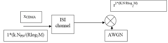
For the model of a wireless mobile communication channel [15–18] to be realistic, it has to include many aspects, fading phase & frequency distortion, inter-symbol, co-channel & multiple access interference, near far cross talk as well as colored and white noise also influences a transmitter [19, 21, 24]. Here we will model only AWGN & ISI referred in Fig. 2. The functional channel equation is r = HxCDM A +w. WhereH is the ISI channel can be seen as a delay spread in time or as multipath fading [17–19, 22, 26] and can be modeled by a tapped delay line.
Figure 2. Fundamental channel model with AWGN & ISI.
This is produced as Gaussian distributed thermal noise in electronic device. And SNR is defined as SN R = 10 log10(Eb
N0), where N0/2 corresponds to two sided power spectral density. This explains SNR allows a comparison of performances with respect to the transmitted bits not symbols. Fig. 3 refers to the magnitude & frequency response characteristics of the Microwave channel under investigation.
0 100 200 300 400 500 100
Magnitude of Impulse Response Coefficients
0 50 100 150 200 250 300 350 400 450 500 0
1 2 3
Frequency Response Magnitude
Figure 3. Magnitude & frequency response of the microwave channel under investigation.
4. TURBO-SCHEME RECEIVER
18 Kundu, Sarkar, and Chakrabarty
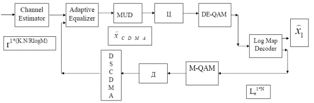
The receiver [1–3] has to reverse all the modifications, processing steps and influences that were done to the user’s data in inverse order. That implies it has to overcome the noise and interference of the physical transmission by channel estimation and equalization to detect single users out of the multi user babble, to de-interleave and demodulate and finally to decode the Turbo Code (TC).
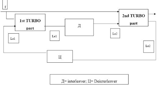
Figure 5. Information flow in a turbo-decoding scheme.
As each of the steps on the transmission side added some kind of coding gain to increase the reliability of the transmission, all the parts of the receiver help to enhance the performance in regard to achievable bit error rate. This is done iteratively in a turbo manner i.e., with the help of side information about bit probabilities gained. The information flow in a general turbo decoding scheme can be shown in the Fig. 5. The received sequence serves as input to both decoder parts, but each uses only part of sequences that was generated by one of the encoder. The extrinsic information (Le1, Le2) gained by soft decisions from one decoder part is used as a priori side information (La2, La1) for the other and vice versa. It is important however, that no information gained from one decoder, as the positive feedback would mean an unstable system. The log-like hood ratio (LLR) for bit probabilities have two main advantages, first lower computational complexity and secondly a direct & demonstrative measure for the probability as well as sign of each bit. The extrinsic information is
calculated by the following formula Le,a = LLR = log
fx(xk= +1|rk)
fx(xk=−1|rk)
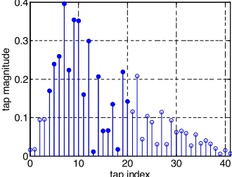
parts, the primary channel estimation by sending a training sequence and the subsequent improvement of this estimation in the equalizer. So instead of generating a special training sequence at the transmitter and sending it in front of the actual data after all the encoding steps, the MATLAB implementation simply generates a single user random BPSK sequence of lengthKtr and applies the same channel model (ISI & AWGN) to it, as only the influence of the channel is of interest for channel estimation. So first the channel estimator tries to equalize the distortion during training by assuming the sequence to be known at the receiver & then to obtain the optimum filter parameters, and then the data is equalized accordingly to this (several times iteratively repeated) first estimation. The special adaptive turbo equalization improves this channel estimation by “tracking” in a decision directed mode during Turbo equalization process, i.e., not only from one data symbol, the filter tap coefficients is updated (referred in Fig. 6), but also from one iteration to the next. The advantage is that the system learns to adapt the environment.
0 10 20 30 40
0 0.1 0.2 0.3 0.4
tap index
tap magni
tu
de
Figure 6. The tap magnitude & indexing in a particular instant of learning.
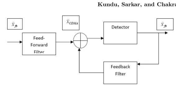
The main part of this estimation is an adaptive decision feedback equalizer as shown in the Fig. 7. The feed forward & feedback filter of such a DFE are FIR filters with Lf & Lb symbol spaced taps having adjustable coefficientsfl&bl. As there is a recursive structure from the detector output to the feedback filter, it has nonlinear characteristics. Its soft output will be in the mathematical form as
xCDM A[K] = Lf
l=1
flr[k−l]− Lb
l=1
bl
xf b[k−l], where
xf b=sign(
xCDM A)
20 Kundu, Sarkar, and Chakrabarty
Figure 7. Adaptive decision feedback equalizer with feed forward filter.
This is used in first iteration, from the second iteration on the feedback filter coefficientsblare approximated and calculated from the priori information so that xf b = 2a. The advantage we find here over a linear equalization or a zero forcing equalizer, primarily its capability to handle ISI channels with spectral nulls, but DFE [7–10] are not the optimum equalizer solutions in terms of performances. It is obvious that the simulated result of MMSE MAP sequence detectors performances is better than having higher computational complexity. We may use any adaptive update algorithm, for simplicity here we took MMSE, LMS, and Sharp LMS, NLMS for the mathematical simulation.
f[k] =f[k−1] +µfe[k]r[k]; b[k] =b[k−1]−µbe[k]
xf b[k] where µf & µb are the adaptation constants i.e., step sizes for adaptation ande[k] =La[k]−
xCDM A[k]; at each time instant kLMS algorithm tries to minimize the MSE by estimating the gradient vector of the method of steepest descent. By the choice of the step size the speed of the convergence can be influenced. Larger step size bring a faster convergence but we need to compromise for higher fluctuation of the minimum error noise floor. The selection of good step size is a very good critical task even though we find some theoretical limits like 0 < µ < t 1
r(R); where tr(R) denotes the trace of the input
expressed as
W[k] =W[k−1] +µwe[k]Fq(X[k]) (4) Here
[Fq(X[k])]l= |
xl[k]|q−1sign(xl[k]) L
m=1
|xm[k]|q
if 1≤q <∞
or
1
xn[k]
δi−n if q =∞
where W[k] represents the filter taps,X1[k] is the Lf b samples of the input signals in the filter memory at time k,δj is the kronecker delta function & nis any integer for which |xn[k]|= max1<j≤L|xj[k]|. The minimization of W[k+ 1]−W[k] with respect tox[k]−Wk+1T Xk= 0 shows the optimization problem. The filter coefficient adaptation is explained by
Wl[k+ 1] =wl[k] +µwe[k]xi[k] if |xi[k]|= max
1<j<L|xj[k]| otherwise wl[k]
Here wl stands for fl orbl respectively andx denotes either r or
xf b. The error calculated as x[k]−xTCDM A[k]bk only one filter coefficients is updated at each time for q = ∞, the algorithm yields a version of NLMS that minimizes L∞-norm, simple but better performance, is called modified NLMS [25]. Its cost function has very small optimum region.
5. SHARPNESS ANALYSIS OF PROPOSED ALGORITHM FOR TURBO-EQUALIZATION
The sequence yk is assumed to be generated from input data xk in a linear way following the equation yk=
i
wkixik.
The weight vector wk = [w1k, . . . , wkn] is updated at each iteration k byxkwik+1=wki +µwki(yk−
yk)xik whereµis a small step size. The general update strategy may be approximated
wk+1i =wikexp
µδL(yk, yk)
δwi k
(5)
where cost function is L(yk,
yk) = (yk−
22 Kundu, Sarkar, and Chakrabarty
term ofµ2 or higher. The last expression can be modified by estimating
yk bywki =γ(zki) = 14(z i
k)2 for some parameter valuez. now if we take the algorithm as adapting over zspace we can use Euclidean gradient descent
Zk+1i =zik−µδL(yk, yk)
δzik (6)
The gradient term becomes
δL δ(yk).
δ(yk)
δwi k
.δ(w
i k)
δzi k
=−2(yk−
yk)xikγ(zki) (7 )
Now we absorb the factor 2 into step size to get Zi
k+1 = zki +
µγ(zki)(yk−
yk)xik. Here we are truly interested in the effective update rule for w, not z and that is used to generate our estimate yk; since
wi
k+1 = γ(zk+1i ) = γ(zki + Small term), in most of signal processing & communication application the weights are not constrained to be positive, as is required by this update rule. So for simplicity here we take
yk= i
sgn(zki)(zki)2xik (8) and Euclidean gradient algorithm inz space becomes
Zk+1i =zik+µzik(yk−
yk)xik (9) and effective update forz space will be
wik+1=wki +µ2wik+t2 yk−
ykxik (10) In order to gain some insight as to the shape of the cost surface in
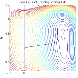
zspace such that the algorithm referred here evolves over the intuition gained from a 10 tap filter under design. Here the equation referred has been compared with standard widrow’s LMS algorithm and named as sharp LMS algorithm and parameterized as
wki =γzki= 1 2sgn
zki zik2+εxik; (11) so the vectorz, that get mapped byγ ontow. for readers consequences this is to say that both are gradient descent algorithm & the Fig. 8 refers the plot of cost surface over which they are evolving. Fig. 8 shows the standard LMS with MSE costL=E(yk−
of the same cost function but gradient is with respect to z so Fig. 9 referred is the MSE cost plotted against axesz1 &z2. Fig. 10 & Fig. 11 refer the Change of MSE with symbol number and change of the tap value with number of taps.
Figure 8. Standard LMS with MSE cost surface.
Figure 9. Sharp LMS with MSE cost surface.
Figure 10. Symbol number with MSE plot for Turbo Equalizer following Descent algorithm.
Figure 11. Change of tap value with tap number.
6. LOG-MAP TURBO DECODER
24 Kundu, Sarkar, and Chakrabarty
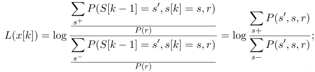
the next iteration for equalization and so on. The TURBO CODE itself again consists of two of the iteratively connected parts dealing with two consistent codes. The main principle is to use LLR with expression
L(x[k]) = logp(x[k] = +1|r)
p(x[k] =−1|r) (12) The Turbo trellis diagram description changes this equation to a complicated one
L(x[k]) = log
s+
P(S[k−1] =s, s[k] =s, r) P(r)
s−
P(S[k−1] =s, s[k] =s, r) P(r)
= log
s+
P(s, s, r)
s−
P(s, s, r);
(13) here s± are the sets of all trellis state transmitting from a state s to s caused by a data input of ±1. Hence the input sequence is denoted as the received signal r as this is the usual case for Turbo coding. The previous equation can be reduced as P(s, s, r) = αk−1(s)·γk(s, s)·
βk(s) with the necessary probabilities αk−1(s) = P(s[k] = s, r1k),
γk(s, s) =P(s[k] =s, r[k]|s[k−1] =s andβk(s) =P(rNk+1s[k] =s). Using the advantage of iterative decoding repetitions, the equation can be rearranged in the following fashion
L(xk) = log
P(r|xk= +1)
P(r|xk=−1)
+ logP(xk = +1)
P(xk =−1)
; (14)
This second term of this equation stands for a priori LLR that would be 0 in a conventional decoding scheme without this kind of side information about certain bit probabilities.
Figure 12. Equalizer error history with iteration number; number of tap:6 with NLMS algo.
Figure 13. Channel frequency response normalized to baud frequency.
26 Kundu, Sarkar, and Chakrabarty
Figure 15 shows the channel & combined channel equalizer after implementing the turbo coding. Fig. 16 shows cost & achievable bit rate versus the iteration number. The fact the cost is not monotonically decreasing in the first few hundreds samples, its because of the initial stage the algorithm no longer be a perfect gradient descent algorithm (though it in approximately so). From Fig. 17, it can be said that adaptive turbo equalizer can rapidly provide a solution approximately the Max SNR solution. Fig. 18 shows BER curves for system employing (using various adaptive algorithm) turbo equalization and without turbo equalization. The data point for each SNR values was obtained by averaging over all carriers for the block & repeating for a total of two channel realization.
Figure 15. Initial and final tap index for Turbo Equalizer.
Figure 16. Achievable bit-rate versus time.
Figure 17. Inverse of shortened SNR versus time.
Figure 19. Channel input output introduces noise and zero errors after channel equalization.
7. CONCLUSION
Equalization of multiple user mobile channels is implemented observed and evaluated which requires exhaustive mathematical calculations. All the simulations have been done in MATLAB version 7.14. Turbo Equalizer with various form of steepest descent algorithm shows after equalization we can extract the exact bit patterns with zero errors (referred in Fig. 19). The results suggest that the procedure is well suited for multicarrier system with global convergence of algorithm.
ACKNOWLEDGMENT
The authors are grateful to Space Application Centre (SAC) Ahmadabad, ISRO for funding similar type of Research Project “Study Simulation & Analysis of Adaptive antenna array for Satellite based mobile communication” under which this work has been done.
REFERENCES
1. Lee, F. K. H. and P. J. Mclane, “Parallel-trellis turbo equalizers for sparse-coded transmission over SISO and MIMO sparse multipath channels,” IEEE Transactions on Wireless Communications, Vol. 5, Issue 12, 3568–3578, December 2006.
28 Kundu, Sarkar, and Chakrabarty
Symposium on Signals, Systems, and Electronics, 1998. ISSSE 98, 460–464, Sept. 29–Oct. 2, 1998.
3. Peacock, M. J. M. and I. B. Collings, “Mutual information analysis of turbo equalizers for fixed and fading channels,” IEEE International Conference on Communications, 2003. ICC ’03, Vol. 4, 2938–2942, May 11–15, 2003.
4. Trajkovic, V. and P. Rapajic, “Adaptive decision feedback turbo equalization and multiuser detection,” 2004 IEEE Eighth International Symposium on Spread Spectrum Techniques and Applications, 540–544, Aug. 30–Sept. 2, 2004.
5. Vogelbruch, F., R. Zukunft, and S. Haar, “16-QAM turbo equalization based on minimum mean squared error linear equalization,” Conference Record of the Thirty-Sixth Asilomar Conference on Signals, Systems and Computers, 2002, Vol. 2, 1943–1947, Nov. 3–6, 2002.
6. Liu, Z., J. Wang, C. Zhao, J. Wang, and M. Jiang, “A novel turbo equalization for MIMO frequency selective fading channels,”
2006 International Conference on Communications, Circuits and Systems Proceedings, Vol. 2, 1063–1067, June 25–28, 2006. 7. Park, J. and S. B. Gelfand, “Sparse MAP equalizers for turbo
equalizations,”IEEE 61st Vehicular Technology Conference, 2005, Vol. 2, 762–766, May 30–June 1, 2005.
8. Song, S., A. C. Singer, and K.-M. Sung, “Turbo equalization with an unknown channel,” IEEE International Conference on Acoustics, Speech, and Signal Processing, 2002. Proceedings. (ICASSP ’02), Vol. 3, III-2805–III-2808, May 13–17, 2002. 9. Kim, J.-H. and Y.-H. You, “Pilot-free frequency tracking method
for ultra-wideband receivers,” Progress In Electromagnetics Research, PIER 82, 65–75, 2008.
10. Lee, Y.-D., D.-H. Park, and H.-K. Song, “Improved channel estimation and MAI-robust schemes for wireless of DMA system,”
Progress In Electromagnetics Research, PIER 81, 213–223, 2008. 11. Mishra, M. and S. Konar, “High bit rate dense dispersion managed
optical communication systems with distributed amplification,”
Progress In Electromagnetics Research, PIER 78, 301–320, 2008. 12. Tripathi, R., R. Gangwar, and N. Singh, “Reduction of crosstalk
in wavelength division multiplexed fiber optic communication systems,” Progress In Electromagnetics Research, PIER 77, 367– 378, 2007.
and a rake receiver approach,” Progress In Electromagnetics Research, PIER 76, 413–425, 2007.
14. Tarhuni, N. G., M. Elmusrati, and T. Korhonenn, “Multi-Class Optical-CDMA network using optical power control,”Progress In Electromagnetics Research, PIER 64, 279–292, 2006.
15. Kundu, A. and A. Chakrabarty, “Fractionally spaced constant modulus algorithm for wireless channel equalization,”Progress In Electromagnetics Research B, Vol. 4, 237–248, 2008.
16. Usman, M., R. A. Abd-Alhameed, and P. S. Excell, “Design considerations of MIMO antennas for mobile phones,” PIERS Online, Vol. 4, No. 1, 121–125, 2008.
17. Wang, W., Y. Zhang, K. Zhou, and H. Zhang, “Research on asymmetric characteristics of mobile communications system based on electromagnetic radiation,”PIERS Online, Vol. 3, No. 8, 1298–1302, 2007.
18. Arnetz, B. B., T. Akerstedt, L. Hillert, A. Lowden, N. Kuster, and C. Wiholm, “The effects of 884 MHz GSM wireless communication signals on self-reported symptom and sleep (EEG) — An experimental provocation study,” PIERS Online, Vol. 3, No. 7, 1148–1150, 2007.
19. Wang, F., Y. Xiong, and X. Yang, “Approximate ML detection based on MMSE for MIMO systems,”PIERS Online, Vol. 3, No. 4, 475–480, 2007.
20. Zhao, J., J. Zhou, N. Xie, J. Zhai, and L. Zhang, “Error analysis and compensation algorithm for digital predistortion systems,”
PIERS Online, Vol. 2, No. 6, 702–705, 2006.
21. Abouda, A. A., H. M. El-Sallabi, L. Vuokko, and S. G. H¨aggman, “Spatial smoothing effect on kronecker MIMO channel model in urban microcells,” Journal of Electromagnetic Waves and Applications, Vol. 21, No. 5, 681–696, Apr. 2007.
22. Li, H.-J., T.-Y. Liu, and J.-L. Leou, “Antenna measurements in the presence of multipath waves,” Progress In Electromagnetics Research, PIER 30, 157–178, 2001.
23. Ohta, M., Y. Mitani, and H. Ogawa, “Multi-dimensional generalization in space and time domains for Middleton’s study in stochastic evaluation of correlative many EM noise processes,”
Progress In Electromagnetics Research, PIER 24, 97–118, 1999. 24. Wang, X., P. R. P. Hoole, and E. Gunawan, “An
30 Kundu, Sarkar, and Chakrabarty
25. Kundu, A. and A. Chakrabarty, “Frequency domain NLMS algorithm for enhanced jam resistant GPS receiver,” Progress In Electromagnetics Research Letters, Vol. 3, 69–78, 2008.