IJEDR1503122
International Journal of Engineering Development and Research (www.ijedr.org)1
Dynamic Response of a Launch Vehicle to Wind
Gust
1Aayillia K Jayasidhan, 2Jancy Rose K, 3R.Neetha
1P. G. Student, Department of Civil Engineering, SSET, Kochi, Kerala 2Scientist-SF,SDSD/SDMG/STR, ISRO, Thiruvananthapuram, Kerala
3Head, SDSD/SDMG/STR, ISRO, Thiruvananthapuram, Kerala
________________________________________________________________________________________________________ Abstract - The computation of dynamic loads on a launch vehicle due to atmospheric gust is essential for the design of launch vehicle structural systems. Launch vehicle can encounter gusts at any time during the flight. The gust models are of different patterns. This results in analysing many cases to identify the critical load condition for structural design of launch vehicle. Generating the finite element models at various time instances using the pre-processor of any standard FEM package and gust models of various patterns at critical flight instances are tedious and time consuming. A Multistage Launch Vehicle is analysed to study the gust response at various time instants during flight. Finite Element Model of the Launch Vehicle at lift off is generated using a standard FEM Package. A software called ‘GUST_SIMULATION’ is developed for generating finite element models at various time instances from the lift off model and for generating the gust models at various time instants. As large number of result files are generated automatically, post processing of the gust load analysis using FEM packages is time consuming. So, for extracting the gust response from the output file of the FEM package, another software ‘GUSTRUN’ is developed. The results are analyzed to get the critical load case.
Index Terms–Launch Vehicle, Gust, mach number, flight conditions, Modal analysis, Transient response analysis
________________________________________________________________________________________________________
I.INTRODUCTION
The computation of dynamic loads on a launch vehicle due to atmospheric gust is essential for the design of launch vehicle structural systems. Launch vehicle can encounter gusts at any time during the flight. This results in analysing many cases to identify the critical load condition for structural design of launch vehicle. Generating the finite element models at various time instances using the pre-processor of any standard FEM package and gust models of various patterns at critical flight instances are tedious and time consuming. Hence an attempt is made to generate a software to carry out the analysis at various time instances automatically. The objective of the present study is to generate a software to carry out, automatically, the dynamic response of a typical multistage launch vehicle at various time instances using different gust patterns and process the results in a single run. This requires generation of finite element models of the launch vehicle at different time instants of flight from the available FE model of the vehicle at liftoff and generation of the corresponding gust models at various altitude.
II.LITERATURE SURVEY
As early as 1964, Lester and Tolesfson[1] suggested that the detailed characteristics of measured wind profiles be used to establish the response of launch vehicles to turbulence. However, because of computational considerations launch vehicle gust loads analyses have generally involved the use of synthetic gust profiles whose properties were established from aircraft response data or wind profile measurement. H.B.Tolefron[2], presents the available data on the derived gust velocities in thunderstorms for altitudes upto 34,000 feet, from previously evaluated effective gust velocities through use of a conversion factor that is a function of airplane characteristics and altitude..
Harry Press and Roy Steiner[3] addressed the issue of whether gusts derived from horizontally flying aircraft could be applied to a rising launch vehicle. This study might be considered to apply best to missile operations in flight paths similar to airplanes and to apply only in a crude way to nearly vertical flight paths. Homer G. Morgan and Dennis F. Collins[4], in 1962 determined the response of Launch Vehicle to a number of detailed wind profile. Authors compared the response of vehicle flying through detailed profiles with the response of the same vehicle flying through balloon-measured profiles. The response to the detailed wind profiles, relative to the balloon-measured profiles, is characterized by the large excitation of the rigid pitch and elastic bending modes.
Detailed high resolution wind profiles as measured by the Jimsphere system. Orvel E. Smith and Lambert D. Austin[5] present the results indicating the significant role played by the ascent wind environment in the design and launch-commit criteria of Space Shuttle Vehicle.
IJEDR1503122
International Journal of Engineering Development and Research (www.ijedr.org)2
Historically, launch vehicle gust loads have been calculated by applying a synthetic gust profile whose amplitude, wavelength, and shape were selected to induce loads of a desired magnitude. The two most common synthetic profiles used today are one-cosine profile and the one-minus one-cosine with a flattop profile. Other profiles that have been suggested, and/or used include sharp-edged and linear-ramp profiles, triangular, trapezoidal, and sine profiles and Z-shaped profile. M. C. Kim et. al.[7,8] introduce a Monte Carlo gust loads analysis approach that uses the turbulent component of measured wind profiles as forcing functions, and establishes loads of a desired statistical level. They describe the actual gust load analysis [6] and compares the results to loads obtained with the most widely used synthetic profile approach.For analyses of spacecraft vehicles, wind gusts can be treated as either random (spectral turbulence) or discrete. For random gusts, typical spectral models include the Von Karman and Dryden turbulence models. The Von Karman model has widely been considered the more "realistic" model when it comes to defining turbulence spectra. However, due to the computational complexity of the Von Karman model, the Dryden model is typically used in aerospace vehicle analyses. Frank B. Leahy[9] presents the development of the MIL-SPEC curve, and provides the necessary information to calculate discrete gust magnitudes as a function of both gust half wavelength and the desired probability level of exceeding a specified gust magnitude.
In the present work, elastic response of launch vehicle to sinusoidal gust at various time instances is carried out and thereby computed the dynamic (Design) loads on launch vehicle. The elastic vehicle resonant response to sinusoidal gusts determine the critical design loads. Software development is done to generate the finite element models of typical launch vehicle at different time instants of flight.
III.OBJECTIVES
1. To develop a software for generating the finite element models of a typical launch vehicle at different time instants of flight from the FE model of the vehicle at lift off.
2. To develop a software for generating gust models at various time instances for gust response studies 3. To carry out gust response studies at various time instances and flight conditions automatically.
4. To estimate the dynamic response of launch vehicle under gust loads, thereby compute the dynamic (Design) loads on launch vehicle
IV.DYNAMIC RESPONSE ANALYSIS OF LAUNCH VEHICLE
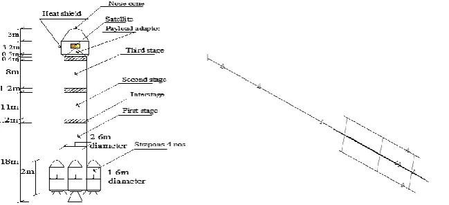
Structural dynamic characteristics of the vehicle like frequency, mode shape, etc., are generated through finite element analysis. Fig. 1 shows the Finite element idealization of a Launch vehicle by beam elements. Launch vehicle under study is a 3 stage vehicle with four strapons attached to the core of first stage.
Large forces normal to the centre line of the launch vehicle (lift forces) can be created by gusts and other transient wind effects. The sudden gust velocity vector, when added to the vehicle’s airspeed vector, causes a small angle of attack α. Aerodynamic Normal Force is expressed by the relation,
Normal Force=CL
1 2𝜌 𝑉
2 𝑆 = 𝜕𝐶𝐿
𝜕∝ ∝
1 2𝜌 𝑉
2 𝑆= 𝜕𝐶𝐿
𝜕∝ ∝ q S (1)
Where ‘𝑆𝜕𝐶𝑁
𝜕∝ ′ is the lateral aerodynamic force coefficient, ‘q’ is the dynamic pressure, ‘∝ ′ is the angle of attack of Launch vehicle flight path.
In the formulation of gust response, the lateral aerodynamic force coefficient (𝑆𝜕𝐶𝐿
𝜕∝)given in Eq. 1 is converted into concentrated aerodynamic force coefficient (SCL). Then, the resulting equation for gust response will become,
FAero, i= SCL,i ×q× ∝ (2)
Where ‘FAero,i’is the aerodynamic force at ith station of vehicle and ‘SCN,i’ is the lateral aerodynamic force coefficient at
ith station.
IJEDR1503122
International Journal of Engineering Development and Research (www.ijedr.org)3
In the response calculations, the aero forces are assumed to act normal to the vehicle longitudinal axis. This results in a time-varying deviation from the relatively small vehicle angle of attack caused by the vehicle's motion through the atmosphere. It is also assumed that the launch vehicle is immersed in the gust profile instantaneously. Therefore, the gust velocity profile becomes a time dependent modulation of the local angle of attack along the length of the vehicle.Modal Analysis
Modal Analysis is carried out to determine the natural frequency of the structure. The Launch Vehicle is idealised into a beam model with free end boundary conditions as the dynamic characteristics during flight is considered. For the Launch Vehicle assembly, the dynamic characteristics changes with time . Therefore, the natural frequency of the structure also changes with time. But, in the present work, the change in natural frequency with time is negligible since the mass variation is small for the time duration considered for the study. The forces and masses along the vehicle cause the elastic bending to acquire a definite, predictable, shape or ‘natural mode’. The shape is time-dependent and bends in and out of shape at a set frequency like a vibrating ruler. And it’s not just one mode, it’s actually a combination of several independent natural modes: each mode vibrates at a certain (successively higher) frequency which may set in motion by gusts and turbulence of a similar frequency. Natural frequency and mode shapes obtained from modal analysis of Launch vehicle assembly is shown in Table 1.
It’s worth noting that successively higher bending modes have less and less effect (smaller amplitude), so can be neglected: if analysing a full size large launch vehicle, attention would be paid to only the first three or four bending modes. It should be noted that these standing waves oscillate: half a cycle later, each picture gets turned upside-down. From the modes shapes of beam assembly it can be seen that a modal displacement at forward portion of vehicle is large compared to aft-end portion. This is because the mass in the aft portion is very high compared to forward portion. Therefore, for mass balancing, forward portion which has less mass has to bend more compared to aft portion.
Transient Response Analysis
Transient response analysis is the most general method for computing forced dynamic response. The purpose of transient response analysis is to compute the behavior of a structure subjected to time varying excitations. All of the forces applied to the structure are known at each instant in time. Effect of gust on the launch vehicle varies with the frequency, mach number and flight conditions. A software called ‘GUST_SIMULATION’ is developed. This software can generate the finite element models of typical launch vehicles at different time instants of flight from the lift off model. This program generate gust models for various time instances at which FE models of launch vehicles are generated for gust response studies. This software can be considered as a analytical tool capable of generating the gust load input for any type of Launch Vehicle. The output of this program in conjunction with software ‘GUSTRUN’ can solve and update the data of input file of a standard FEM package,, generate the result files at different flight conditions and mach number. Because of the random nature of wind gusts, realistic models of horizontal and vertical gust components are difficult to obtain. In this work, wind gusts is tackled directly in the time domain with the use of a analytical tool developed using FORTRAN.
The gust load analysis is performed to establish the dynamic response of the vehicle, and its payload, to the turbulence that might be encountered on any given flight. The analysis is accomplished by instantaneously enveloping the vehicle in a synthetic gust model, which in effect is a time dependant modulation of local angle of attack along the length of the vehicle. The amplitude, shape, and wavelength of the gusts are selected to induce vehicle loads that are equivalent to a desired statistical conservatism. To establish proper loads, the simulation includes three flight conditions at different mach numbers. Simulation was performed for mach numbers values of 1.05(case 1), 1.1(case 2) and 1.2(case3). And the analysis performed with model here has given typically frequency content up to 50Hz. However, the primary response is below 10Hz for most vehicle/payload system.
Launch Vehicle model components (core, rocket motors, upper stage, fairing, etc.) are coupled to form the system model. Sinusoidal gust profiles tuned to the vehicles fundamental bending modes are applied to the Launch vehicles.
Table 1: Natural Frequencies of Launch Vehicle
Mode Frequency(Hz) Mode Shape
1st lateral bending mode in XY plane 1.5
2nd lateral bending mode in XY plane 2.6
IJEDR1503122
International Journal of Engineering Development and Research (www.ijedr.org)4
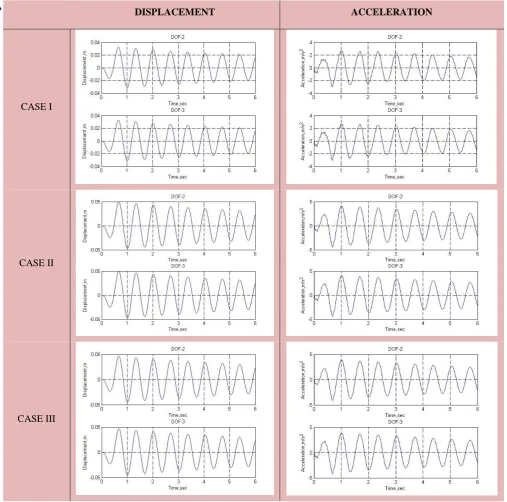
Gust Response-Gusts are often considered to act normal to the vehicle axis, and are assumed to be represented by simple discrete time functions. In other cases, gusts are treated statistically by power spectral techniques. The gust analysis should include tuning gusts at various altitudes. In this work, a discrete sinusoidal gust environment is considered. The sinusoidal function is tuned to the critical bending frequencies of the vehicle.Response at Engine Points- Maximum displacement is obtained for mach number 1.1 and maximum acceleration for mach number 1.05. The displacement is found to be maximum at first mode and acceleration was found to be maximum for third mode. Out of all the three cases Maximum displacement and acceleration for all cases is shown in Fig. 2.
DISPLACEMENT ACCELERATION
CASE I
CASE II
CASE III
IJEDR1503122
International Journal of Engineering Development and Research (www.ijedr.org)5
Response at Satellite Location- The displacement value is found to be higher for first mode and the value decreases with higher modes. Maximum displacement value is obtained for the mach number 1.1. All three cases of loading produce maximum displacement for this mach number. Out of this Case II generates maximum displacement value of 49.216mm in lateral direction. Maximum displacement plots for the three cases were shown in Fig.3.V.DISCUSSIONS
Transient response analysis of a Multistage Launch Vehicle to wind gust are carried out. For carrying out Gust load analysis software is developed in FORTRAN 95. The generality of software is evidenced by its multiple phase simulation capability. The software can be used for the gust response studies of any type of Launch Vehicle. The software is validated by its application for gust response analysis of a multistage launch vehicle. Software developed for the extraction of gust response helps to identify the critical case.
In the simulation, gust load is tuned to the natural frequencies of launch vehicle obtained from the modal analysis. From the analysis results it can be seen that the launch vehicle flight through Case II loading with a mach number 1.1 generate maximum response at the upper stage of vehicle. The response of engine points are quite smaller compared to the response of satellite and heat shield portion. In the present study a method for modelling finite element model and wind gust at various time instances requested by the user is developed. Analysis is carried out in user programmable mode by updating the aero data is made use for
DISPLACEMENT ACCELERATION
CASE I
CASE II
CASE III
IJEDR1503122
International Journal of Engineering Development and Research (www.ijedr.org)6
the development of gust models at various time instants. Since the time interval considered here is very small, the change in mass of the body due to propellant consumption is negligible in this analysis.VI.CONCLUSIONS
The computation of gust loads on the structure of launch vehicle is a part of the engineering work during the development and certification phases of a new project. The physical situation such as wind gust encountered by launch vehicle during its flight gets repeated many times. Therefore, a large number of records will be available for various time instants. Out of these, estimation of critical condition becomes tedious when the normal method of analysis with some standard FEM packages is used. To overcome these difficulties, a methodology was developed for performing gust load analysis at various time instances for different gust models automatically. A software called ‘GUST_SIMULATION’ is developed for generating finite element models at various time instances from the lift off model of a multistage launch vehicle and for generating the corresponding gust models. For extracting the gust response from the output file of the FEM package, another software, ‘GUSTRUN’, is developed. The results are analyzed to get the critical load case. This work provides input for the structural design of launch vehicle subsystems.
REFERENCES
[1] Harold C. Lester and Harold B. Tolefson, “A Study of Launch Vehicle Response to Detailed Characteristics of the Wind Profile”, NASA Langley Research Centre, Langley Station, Va., March 1964
[2] Tolefson. H. B., “Summary of Derived Gust Velocities obtained from measurements within Thunderstorms,” NACA Report 1285, Langley
Aeronautical Laboratory, Langley Field, VA July 27,1955
[3] Harry Press and Roy Steiner, “An approach to the problem of estimating severe and repeated gust loads for missile operations”, National
Advisory Committee for Aeronautical Note 4332, Langley Aeronautical Laboratory, Langley Field-Washington, September 1958
[4] Homer G. Morgan and Dennis F. Collins, “Some Applications of Detailed Wind Profile Data to Launch Vehicle Response Problems”,
NASA Langley Research Centre, Langley Air Force Base, Va. Phoenix, Arizona, April 3-5, 1962
[5] Orvel E. Smith, Lambert D. Austin, Jr., “Sensitivity Analysis of the Space Shuttle to Ascent Wind Profiles”, National Aeronautics and
Space Administration Technical Paper, March 1982
[6] S. I. Adelfang and O. E. Smith, “Gust Models for Launch Vehicle Ascent,” American Institute of Aeronautics and Astronautics, Inc,1998 [7] M. C. Kim, A. M. Kabe, S. S. Lee, “Atmospheric Flight Gust Loads Analysis,” Statistics & Satellite Replenishment Office, Structural
Dynamics Department, 1999
[8] M. C. Kim, A. M. Kabe, J. B. Clark, “Statistical Analysis of Atmospheric Flight Gust Loads Analysis Data”, Statistics & Satellite
Replenishment Office, Structural Dynamics Department, 1999
[9] Frank B. Leahy, “Discrete Gust Model for Launch Vehicle Assessments,” NASA/Marshall Space Flight Center, Natural Environments
Branch, AMS Annual Meeting 12th Conference on Aviation, Range and Aerospace Meteorology, January 2008
[10] Glenn Hrinda, “Single-Point-Attachment Wind Damper for Launch Vehicle On-Pad Motion”,NASA Langley Research Center, Hampton, Virginia, American Institute of Aeronautics and Astronautics, July 2009
[11] Rick Newlands, Martin Heywood and Andy Lee, “Rocket Vehicle Loads and Airframe Design”, ASPIRE SPACE, Technical papers, 2012 [12] James R. Scoggins and William W. Vaughan, “Problems of Atmospheric Wind Inputs for Missile and Space Vehicle Design”, NASA,
George C. Marshall Space Flight Centre, Huntsville, July 10-12, 1963
[13] X.C.Fung, “Introduction to theory of Aeroelasticity”, Massachusetts Institute of Technology
[14] Ching-Jen Chen,Shenq-Yuh Jaw, ”Fundamentals of Turbulence Modelling”,Inbunden, Engelska, 1997
[15] William T. Thomson, Marie Dillon Dahleh, Chandramouli Padmanabhan, “Theory of Vibrations with Applications”, University of California & IIT Madras, Fifth Edition, Pearson
[16]Raymond L. Bisplinghoff, “Principles of Aero elasticity,” Professor of Aeronautics and Astronautics, Massachusetts Institute of Technology [17] NASA-HDBK-7005, “Dynamic Environmental Criteria”, National Aeronautics and Space Administration, March 13, 2001
[18] B. S. Grewal, “Numerical Methods in Engineering and Science,” Professor of Applied Mathematics, Sixth Edition, Khanna Publishers, May 2002