Coherent Code Tracking for Spatial Transmit
Diversity DS-CDMA Systems
Garrey W. Rice
DSP Enabled Communications Group, Department of Electronic and Electrical Engineering, University of Strathclyde, Glasgow G1 1XW, Scotland, UK
Email:[email protected]
Iain G. Stirling
DSP Enabled Communications Group, Department of Electronic and Electrical Engineering, University of Strathclyde, Glasgow G1 1XW, Scotland, UK
Email:[email protected]
R. W. Stewart
DSP Enabled Communications Group, Department of Electronic and Electrical Engineering, University of Strathclyde, Glasgow G1 1XW, Scotland, UK
Email:[email protected]
Received 6 February 2004; Revised 23 February 2005
Spatial transmit diversity schemes are now well integrated into third-generation cellular mobile communication system specifi-cations. When DS-CDMA-based technology is deployed in typical macro- and microcell environments, multipath diversity and spatial diversity may be exploited simultaneously by a 2D RAKE receiver. The work presented in this paper focuses on taking ad-vantage of spatial transmit diversity in synchronising the 2D RAKE structure. We investigate the use of coherent and noncoherent techniques for tracking the timing parameters of each multipath component. It is shown that both noncoherent and coherent techniques benefit from transmit diversity. Additionally the performance gap between these two techniques increases with the number of antennas.
Keywords and phrases:DS-CDMA, 2D RAKE, transmit diversity, coherent delay-locked loop.
1. INTRODUCTION
For direct-sequence code-division multiple-access (DS-CDMA) communications, antenna diversity techniques have been proposed and implemented to mitigate the effects of multipath fading [1,2]. One economical way of deploying such diversity is to use multiple antennas at the base station, and a single antenna at the mobile station [3]. With such an architecture, uplink reception can be carried out using adap-tive beamforming solutions. Downlink reception relies on the transmission of distinct waveforms at the transmit anten-nas which can then be separated at the single receive antenna. It is well known that CDMA-based systems are able to exploit and recombine signal components of different delays using RAKE-style receiver structures. Recently 2-dimensional (2D) RAKE receivers have been proposed which are designed to exploit both delayed signal components (time diversity) and spatial diversity simultaneously. Al-though time diversity is exploited by the overall operation of a 2D RAKE receiver, it is of no benefit to the delay tracking functions which underpin its operation.
In this paper, we consider techniques for tracking the de-lay of a received signal component when spatial transmit di-versity is employed. Closed loop synchronization techniques are generally used for this purpose. The most popular is the noncoherent delay-locked loop (DLL) [4]. However, the WCDMA (wideband CDMA) specifications provide known pilot symbols in both link directions making the coherent DLL a viable alternative.
The structures described in this paper are well suited to digital implementation. All of the operations that they re-quire are either described in terms of discrete-time signals or have a digital equivalent which is realisable with todays processing capabilities.
2. SYSTEM MODEL
antennas thereby achieving good decorrelation of the chan-nels. Finally provision has been made in the third-generation partnership project (3GPP) specifications for this configura-tion. 3GPP is the body responsible for the standardisation of WCDMA, the emerging high data rate mobile telephony ser-vice.
2.1. Transmitter
3GPP currently specifies antenna diversity with two antennas and utilises the Alamouti space-time block code [5,6]. The potential capacity increase obtained by applying this tech-nique to WCDMA in a 2D RAKE is demonstrated in [3]. Furthermore, there are draft proposals for expansion to four antenna transmitters [7].
In WCDMA different users1 are separated by different
spreading codes. Let us define dk[n] as thenth data sym-bol of the kth user. The data symbols of each user are applied to a block coding scheme to yield M distinct se-quences{dk,1[n]},{dk,2[n]} · · · {dk,M[n]}that are transmit-ted on different antennas ({dk,m[n]}is transmitted on an-tennam). For analysis purposes, it is convenient to provide a representation of the baseband signal which corresponds to userkand is transmitted on themth antenna. This is denoted as
sk,m(t)=
Ec,k M
i
ak[i]dk,m
i Gk
g(t−Tc), (1)
where Ec,k is the energy per chip of the kth user, ak[i] is the user-specific spreading code, Tc is the chip period,Gk is the user’s spreading factor, and g(t) is the chip shaping waveform. Note that in WCDMAak[i] represents the prod-uct of the real-valued user-specific channelisation code and a base-station-specific complex-valued scrambling code [8]. The channelisation codes in WCDMA are orthogonal codes. It is assumed that
ak[i],dk,m[n]∈
ejπ/4,ej3π/4,ej5π/4,ej7π/4 (2)
and also that the energy ing(t) is unity.
In order to exploit transmit diversity, a receiver must be capable of estimating the channel from each BS antenna. This is facilitated by the common pilot channel (CPICH). To troduce the CPICH into our model, we designate user in-dex 1 as the pilot channel. Therefore,{d1,1[n]} · · · {d1,M[n]} represent the pilot symbol sequences which are transmitted on antennas 1· · ·M, respectively. In order to facilitate in-dependent channel estimation from each antenna, the pilot symbols are orthogonal across antennas.
The overall transmitter is shown inFigure 1. The blocks markedg(t) are chip shaping filters. “Other users” refer to other data and control signals which have been chipped by
1Strictly it is different UMTS (Universal Mobile Telecommunications
System) physical channels that are separated by different spreading codes; however, we will denote them as users and reserve the word channel to refer to the wireless propagation environment.
Other users
d1,1[n]
d1,2[n]
d1,M[n]
Scrambling code
g(t) × × ×
g(t) g(t)
ζ1(t)
ζ2(t)
ζM(t) ···
···
· · · · · ·
+ + +
Figure1: Baseband model of transmitter withMCPICHs
trans-mitted onMantennas.
their respective channelisation codes. The pilot channel does not require channelisation and is spread directly by the base-station-specific scrambling code.
The baseband signal which is transmitted on themth an-tenna consists of all user signals summed together as follows:
ζm(t) K
k=1
sk,m(t). (3)
The figure of merit commonly used in a downlink scenario isEc/Ior, whereIoris the one-sided power spectral density of
the entire base station transmission:
Ior lim
T0→∞ 1
T0Rc M
m=1 T0
ζm(t)2 df =
K
k=1
Ec,k. (4)
2.2. Channel model
The radio propagation conditions in this work are modelled based on the following assumptions. Firstly there is no line-of-sight component between transmitter and receiver. Sec-ondly the mobile device is in motion through a complex scat-tering environment which causes fading of the received sig-nal level. Thirdly strong reflections from more distant ob-jects are also received by the mobile station. This results in a frequency-selective (Rayleigh) fading channel model.
The received signal can be described in terms ofP resolv-able multipath components. Each resolvresolv-able path has a fad-ing waveform due to local scatterers. The baseband equiva-lent received signal,r(t), may be expressed as
r(t)= P
p=1
M
m=1
αp,m(t)ζm
t−τp(t)
+n(t), (5)
whereαp,m(t) is the complex fading envelope of the channel between transmit antennamand the receive antenna via path
RRC Timing error
detector Loop filter
NCC
Delay
κ
Rc On-time signal
z[i] (To detector) Control
signal r(t)
Matched
filter Gain
e[n] F(z)
Complex signal Real signal
Figure2: Generic delay-locked loop structure.
2.3. Receiver
The well-known RAKE receiver demodulates a number of resolvable multipath components simultaneously and com-bines the results coherently to improve the SNR [1,2]. The 2D RAKE structure described in [9] employs multiple receive antennas and a beamformer on each branch of the RAKE structure to improve performance. In the downlink scenario currently under consideration, only one antenna is available at the receiver, therefore this technique cannot be applied. However, a 2D RAKE can still be implemented by exploiting transmit diversity on each branch of the RAKE [3,10].
Synchronising a RAKE receiver to a multipath channel consists of two stages. Firstly the receiver must identify and select a set of multipath components to recombine in the RAKE structure. This typically involves searching for paths, or using cross-correlation techniques such as those described in [11]. The second stage, which we address in the remainder of this paper, is to track the delays of the multipath com-ponents through time. These delays can vary due to move-ment of the mobile device and changes in the environmove-ment; therefore they must be tracked independently. This is typi-cally achieved using delay-locked loop structures.
3. CHIP TIMING RECOVERY LOOPS
3.1. Single-antenna delay-locked loops
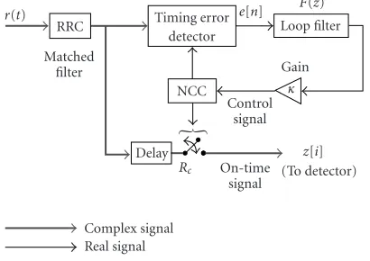
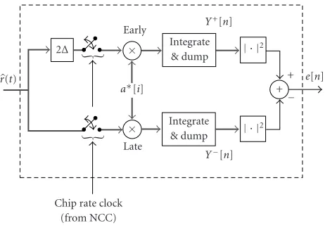
Figure 2shows a generic chip timing recovery loop consist-ing of a timconsist-ing error detector (TED), a loop filter to smooth the TED output, and a numerically controlled clock (NCC) to control the timing of the sampling devices [12]. The or-derof the loop is determined by the transfer function of the loop filter [13]. Here we use a first-order loop by setting the discrete-time transfer function of the loop filter toF(z)=1. The loop bandwidth is then controlled by setting the gain termκ. The performance of a timing recovery loop is ulti-mately limited by the properties of its TED.Figure 3shows an example of a coherent TED for DS-CDMA [14]. A non-coherent version is shown inFigure 4. Both TEDs operate by despreading early and late versions of the received signal to obtainY+[n] andY−[n], respectively.
r(t)
2∆
Early ×
× Late a∗[i]
Integrate & dump
Integrate & dump
+ × ×
(·)∗ | · |
α Channel estimate Chip rate clock
(from NCC)
+ − Y+[n]
Y−[n]
∗ d[n] data
e[n]
Figure3: Single-antenna coherent timing error detector.
Let us assume that the DLL is tracking a path with a delay ofτ1seconds, and the current estimate of this delay is ˜τ1. The
normalised timing error is then defined as
ε(τ1−τ˜1) Tc .
(6)
3.1.1. Coherent DLL
As shown inFigure 3, the coherent TED derives a measure-ment of the timing error (denoted ase[n]) by computing the difference betweenY+[n] andY−[n], and then explicitly re-moving the carrier phase offset and data modulation using knowledge of their values obtained from other parts of the receiver. The error signal developed by this TED may be ex-pressed as
e[n]=Ree−jφ˜dˆ∗[n]Y+[n]−Y−[n], (7)
where ˜φis an estimate of the carrier phase. Taking the expec-tation conditioned on the timing errorε, we obtain
Ee[n]|ε=ERee−jφ˜dˆ∗[n]Y+[n]−Y−[n]. (8)
The carrier phase estimate ˜φis required in any case for co-herent detection of the data. The term ˆd[n] represents either a data decision (i.e., in a decision-directed loop [15]) or a known pilot symbol, depending on which physical channel is being used to derive the timing error.
Let us now examine the statistics of the signals at the out-put of the early and late arms of the detector.Appendix A de-rives the statistics of a despreader output with a timing error ofεchips. The early and late despreader outputsY±[n] are generated by intentionally introducing a timing offset of±∆
chips. Therefore, based on the analysis inAppendix A, it can be shown that the statistics ofY±[n] are
EY±[n]|ε=α1,1G1
EcR0(ε±∆)d1,1[n],
VarY±[n]|ε≈G1V0±
2 ,
r(t)
2∆
Early ×
× Late a∗[i]
Integrate & dump
Integrate & dump
+
Chip rate clock (from NCC)
+ − Y+[n]
Y−[n]
e[n]
| · |
2
| · |2
Figure4: Single-antenna noncoherent timing error detector.
whereV0±is theeffectiveone-sided spectral density of the all
combined interference terms. R0(δ) is the time-normalised
chip shape autocorrelation function:
R0(δ)R
δTc
, R(τ) ∞
−∞g(t)g(t+τ)dt. (10)
These equations are valid under the assumption that other multipath components are significantly spaced from the path being tracked by the loop.
3.1.2. Noncoherent DLL
The noncoherent loop [13] on the other hand assumes no knowledge of the data or carrier phase and they are removed by squaring the early and late despreader outputs, as shown inFigure 4. This causes a reduction in the overall signal-to-noise ratio (SNR) of the timing error measurement, an effect known assquaring loss. The discrete-time error signal for a noncoherent loop is
e[n]=Y+[n]2
−Y−[n]2. (11)
3.1.3. TED comparison
Tables1and2show the final equations for the coherent and noncoherent TED output statistics, respectively. Analysis of the square law devices is performed inAppendix B. The non-coherent equations are then obtained by combining (11) and (9). For the coherent analysis, perfect carrier estimation is assumed as well as knowledge of the data symbols. This is ac-ceptable given that tracking utilizes the CPICH. Both anal-yses also assume that ∆ = 0.5 chips and that square-root Nyquist pulse shaping is used as this guarantees statistical in-dependence of the noise terms on the post despreader early and late branches.
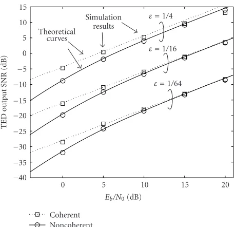
Figure 5shows the SNRs of coherent and noncoherent TED output signals for different timing errors. Simulation results are plotted along with the theoretical curves obtained
Table1: Coherent TED statistics.
E{e|ε} = |α1,1|G1Ec,1[R0(ε+∆)−R0(ε−∆)]
Var{e|ε} =Ec,1|α1,1|2G1V0
Table2: Noncoherent TED statistics.
E{e|ε} = |α1,1|2G21Ec,1[R20(ε+∆)−R20(ε−∆)]
Var{e|ε} =2G1[V0+|s+|2+V0−|s−|2] + 2G21[(V0+)2+ (V0−)2]
s±=α
1,1G1Ec,1R0(ε±∆)
from the equations in Tables1and2. As can be seen, the co-herent detector outperforms the noncoco-herent detector, par-ticularly at low SNRs. The slight discrepancies between the-oretical and empirical results are accounted to self-noise (in-terchip interference due to intentionally sampling too early and too late) and imperfect channel estimation in the simu-lations.
3.2. Exploiting spatial transmit diversity
A suggestion for noncoherent timing error detection which combines the signals from multiple receive antennas is given in [10]. In the present scenario, we apply this by taking early and late measurements of multiple transmit antenna CPICHs as they arrive at a single receive antenna. The de-spreader output of themth CPICH and transmitted by the
mth antenna isYm±[n]. Let us define a pair of vectors which contain the early and late correlation measurements from all antennas:
Y±Y1±[n]Y2±[n]· · ·YM±[n] T
, (12)
whereMis the number of transmit antennas. In [10] a sam-ple autocorrelation matrixΦ±Y Y[n] ofY±[n] is computed by temporal filtering ofY±[n]Y±[n]H. The principle eigenval-ues ofΦ+Y Y[n] andΦ−Y Y[n] are then used to compute a mea-surement of the timing error.
In the present downlink scenario, the mobile station must make regular timing error measurements based on the pilot symbols for each path being tracked. This results in sig-nificant computation to maintain an estimate of the autocor-relation matrix and evaluate the principle eigenvalues. To re-duce complexity and still benefit from the transmit diversity, the following scheme is suggested.
For the noncoherent TED, we simply calculate the timing error as
e[n]= M
m=1
Y+[n]2
−Y−[n]2
=Y+[n]2−Y−[n]2 .
(13)
15 10 5 0 −5 −10 −15 −20 −25 −30 −35 −40
0 5 10 15 20
Eb/N0(dB)
TED
o
utput
S
NR
(dB)
Coherent Noncoherent Theoretical
curves
Simulation results
ε=1/4
ε=1/16
ε=1/64
Figure5: TED output SNRs for different timing errors.
different CPICHs. In addition, as we are summing the out-puts of multiple coherent TEDs, it is appropriate to apply maximal ratio combining at this stage. Therefore, we arrive at the following timing error computation for a multiantenna coherent TED:
e[n]= M
m=1
˜
α∗1,m
Y+
m[n]−Ym−[n]
. (14)
Let us now find an expression for the statistics of the mul-tiantenna coherent TED. Taking into account the reduction in power of each antenna by a factor of Mand employing
Table 1, themth antenna TED statistics are
Eem|ε
=α1,m2G1
Ec,1 M
R0(ε+∆)−R0(ε−∆)
,
Varem|ε
=Ec,1 M α1,m
4 G1V0.
(15)
We may assume that the noise terms are independent since the pilot sequences are orthogonal. Summing across all TEDs, the statistics ofe[n] are
Eem|ε
=G1
Ec,1 M
R0(ε+∆)−R0(ε−∆)
M
m=1
α1,m2
,
Varem|ε
=Ec,1 M G1V0
M
m=1
α1,m4 .
(16)
Ior=1W/Hz BS transmitter
MISO channel
model Multi-input single-output Ant. 1
Ant.N . .
. +
Delay tracking
receiver
AWGN Ioc=Ior−9 dB (other base stations) Downlink channel configuration
Ior=1W/Hz P-CPICH:−10 dB (relative to total BS output)
Figure6: End-to-end simulation configuration.
The SNR at the output of the detector conditioned on the timing error is then
SNR(e|ε)= M
m=1α1,m2 2
M
m=1α1,m4
·G1
R0(ε+∆)−R0(ε−∆)
2
V0 .
(17)
Therefore, we can see that the SNR of the multiantenna tim-ing error measurement increases with the number of anten-nas.
4. SIMULATIONS
4.1. Setup
This section describes a set of computer simulations which were used to evaluate the tracking jitter performance of the delay-locked loops described in Section 3.2. These simula-tions were configured to mimic a realistic set of downlink scenarios compliant with the UMTS specifications.
Figure 6shows the end-to-end simulation configuration which is in agreement with the 3GPP open loop diversity testing procedures set out in [16]. The base station simula-tion was configured to yield a total output power spectral density of Ior = 1 W/Hz. The primary CPICH (P-CPICH)
power level was set to be−10 dB down from the total base station output. The remainder of the BS output was made up of data, control, and synchronisation channels according to [16].
Three distinct configurations were employed: 1 transmit antenna, 2 transmit antennas, and 4 transmit antennas all with a single receive antenna. The total BS output power was constant across all three configurations. The signals were passed through the multiantenna multipath channel model with the power-delay profile shown inFigure 7.
As can be seen, the channel consisted of two multipath components, path 1 and path 2 with propagation delays ofτ1
andτ2, respectively. We define the average relative power of a
path as the average power of its complex signal envelope. For example, the average relative power of pathpis
Pav,p lim T0→∞
1
T0
T0
0
αp,m(t)2 dt
Interfering path
Tracked path
976 ns
τ2 τ1
0
AdB
Delay (s)
A
ver
age
relati
ve
p
o
w
er
(dB)
Figure7: Delay-power profile of channel.
where it is assumed that the average power received through pathpfrom all transmit antennas is the same.
Path 1 was tracked by the coherent and noncoherent chip timing recovery loops described inSection 3.2. The average relative power of this path, denoted asAdB, was varied over
different simulation runs in order to control the SNR. The purpose of path 2 was only to introduce multipath interfer-ence and it was not exploited by the receivers. Note that in a full receiver path 2 would be tracked independently by a separate DLL. Its average power relative to the BS output was fixed to 0 dB.
The motivation for this setup is that a receiver must be able to track individual paths in the presence of other paths. Multipaths are the dominant source of interference in the downlink as they destroy orthogonality between users. The effect of other multipaths on a (despread) path of interest is described by (A.9) inAppendix A.
4.2. Results
Figures 8,9, and10 show the measured normalised mean square tracking jitter results of the simulations for 3 kph, 50 kph, and 120 kph fading channels, respectively. Uncorre-lated fading waveforms were generated using the technique described in [17].
A chip rate of 3.84 Mcps (mega chips per second) and carrier frequency of 2.1 GHz were employed. The most ob-vious feature of these results is the substantial performance increase obtained in all cases by exploiting transmit antenna diversity. This result is as expected from [18]. The perfor-mance advantage due to an increased number of antennas is exacerbated by slow fading. This can be explained by the
drift effect which occurs when a channel enters a deep fade
and the tracking loop is temporarily guided by the noise. In a slow channel, the deep fades are long in duration potentially permitting the tracking device to drift further from the max-imum effect point. Increasing the number of transmit anten-nas reduces the probability of deep fades thereby mitigating the drift effect.
Another point worth noting is that the performance dif-ference between coherent and noncoherent tracking loops tends to increase with the number of antennas. This is be-cause of the decreased SNR at the input to each square law device in the noncoherent detector. From Figure 5,
10−2
10−3
10−4
−12 −10 −8 −6 −4 −2 0
AdB- path attenuation (dB)
M
easur
ed
mean
squar
e
tr
acking
jitt
er
σ
2 ε
Coherent Noncoherent
1 Tx ant.
2 Tx ant.
4 Tx ant.
Figure8: DLL performance-pedestrian (3 kph fading).
it is clear that squaring loss is exacerbated with lower input SNRs thereby reducing the performance of the overall detec-tor.
Finally we note that the 4-antenna configuration is par-ticularly poor for low SNRs. This can also be explained by squaring loss in the case of the noncoherent tracking loop and by the reduced ability to estimate the magnitude and phase of the channel accurately in the case of the coherent loop.
5. CONCLUSION
In this paper, we have presented coherent and noncoherent chip timing recovery loops which use simple schemes to ex-ploit spatial transmit diversity. The motivation is to track the timing parameters of delayed signal components in a (single-antenna) 2D RAKE receiver.
It has been shown that the tracking jitter of delay-locked loops can be reduced with an increase in the number of transmit antennas. The performance gap between the coher-ent and noncohercoher-ent loops is also shown to increase with the number of antennas due to increased squaring loss.
APPENDICES
A. DESPREADER OUTPUT ANALYSIS
The purpose of this appendix is to derive (9) which describe the statistics the despreader output in the presence of syn-chronisation errors. The received baseband signal is given by (5) and for the case of a single transmit antenna becomes
r(t)= P
p=1 αp,1ζ1
t−τp
10−2
10−3
10−4
−12 −10 −8 −6 −4 −2 0
AdB- path attenuation (dB)
M
easur
ed
mean
squar
e
tr
acking
jitt
er
σ
2 ε
Coherent Noncoherent
1 Tx ant.
2 Tx ant.
4 Tx ant.
Figure9: DLL performance-vehicular (50 kph fading).
Let us assume that the RAKE arm of interest is demodulat-ing path p=1 and ˜τ1is an estimate of the this path’s delay.
Passingr(t) through a matched filter then sampling produces the chip rate sequencez[i]:
z[i]= ∞
−∞g
t−iTc−τ˜1
r(t)dt. (A.2)
As part of the despreading processz[i] is multiplied by the complex conjugate of the spreading code to obtain
y[i]z[i]a∗[i]. (A.3)
It is useful to decompose y[i] into its constituent compo-nents. These are
(1) the desired signal;
(2) interference due to synchronisation errors; (3) interference from other multipaths; (4) background noise.
It can be shown that, under the assumption that the mul-tipaths are not closely spaced, only the desired signal con-tributes to the mean of y[i]; the other components con-tribute only to its variance.
A.1. Desired signal component
In order to determine the desired component, we separate the path of interest from the summation in (A.1) and substi-tute (3):
r(t)=α1,1
K
k=1 sk,1
t−τ1
(path or interest)
+ P
p=2 αp,1ζ
t−τp
+n(t).
(A.4)
10−2
10−3
10−4
−12 −10 −8 −6 −4 −2 0
AdB- path attenuation (dB)
M
easur
ed
mean
squar
e
tr
acking
jitt
er
σ
2 ε
Coherent Noncoherent
1 Tx ant.
2 Tx ant.
4 Tx ant.
Figure10: DLL performance-vehicular (120 kph fading).
The component ofz[i] corresponding to the path of interest is
α1,1
K
k=1
Ec,k
j
xk,1[i]R0(j−i+ε), (A.5)
wherexk,m[i]ak[i]dk,m[i/Gk]. This is derived by substi-tuting (1) and (3) into (A.4) and then applying the combined filtering and sampling operation defined in (A.2) to only the path of interest.R0(δ) is defined in (10).
The desired signal component, which we will denote as
yd[i], is found by considering only the user of interest (k=1) in (A.5) multiplied bya∗k[i]:
yd[i]=α1,1
Ec,ud
i
Gk
R0(ε). (A.6)
A.2. Interference due to synchronisation errors
Although orthogonal codes are used to separate users, in the presence of synchronisation errors the user of interest eff ec-tively experiences interchip interference (ICI) from all users. This component is
yICI[i]=α1,1
K
k=1
Ec,k
j =i
a∗u[i]xk,1[j]R0(j−i+ε). (A.7)
Using the properties of the spreading codes described in [13], we find that the variance of the real and imaginary parts of
yICI[i] is
σ2 ICI=
|α1,1|2Ior
2
j =0 R2
A.3. Multipath interference
The variance of y[i] due to other multipath components is bounded by
σMPI2 ≤ Ior
2 P
p=2
αp,12
. (A.9)
A.4. Background noise
Under the assumption that the background noise is addi-tive white Gaussian with a two-sided noise spectral density ofN0/2, it is easily shown that the variance contribution of
background noise to the variance ofy[i] is
σ2 BI=
N0
2 . (A.10)
A.5. Despreader output
Finally the despreader output is found by summingy[i] over theGkchips corresponding to each symbol:
Y[n]
Gkn+Gk−1
i=Gkn
y[i]. (A.11)
The mean is found from (A.6) to be
EY[n]=α1,1Gk
EcR0(ε)d[n]. (A.12)
Combining (A.8), (A.9), and (A.10), we obtain
σ2
Y ≤Gk
σ2
ICI+σMPI2 +σBI2
= GkV0
2 .
(A.13)
Theeffectiveone-sided spectral density of the combined
in-terference terms is
V02
σ2
ICI+σMPI2 +σBI2
. (A.14)
B. COMPLEX SQUARING LOSS
Consider the scenario of Figure 11 where s is a complex random variable with constant amplitude and a random phase. The observation of s(denoted asz) is perturbed by a complex-valued Gaussian noise termn, which has the fol-lowing statistical properties:
E{n} =0, E|n|2=N 0.
(B.1)
Note thatnis complex-valued, therefore
ERe2(n)=EIm2(n)=N0
2 . (B.2)
Observation ofs n
z
s + | · |2 y
Figure11: Squaring a noisy complex signal.
The power of the observation is then measured by taking the square of its magnitude to obtainy= |z|2, and filtering
the result. We will now evaluate the first- and second-order statistics ofy.
The observation and its magnitude squared are defined, respectively, as
zs+n,
y|z|2= |s|2+ 2 Re(sn) +|n|2. (B.3)
Since Re(sn) is clearly zero mean, the expected value ofyis
E{y} =E|s|2+ E2 Re(sn)+ E|n|2
= |s|2+N 0.
(B.4)
The expected value of y2is calculated as follows:
Ey2=E|s|2+ 2 Re(sn) +|n|22
=4ERe2(sn)+ 2E|s|2|n|2+ E|n|4|
+ E|s|4+ 4E|s|2Re(sn)+ 4E|n|2Re(sn).
(B.5) The fourth-order noise term in (B.5) is
E|n|4=ERe4(n)+ EIm4(n)+ 2ERe2(n) Im2(n),
(B.6)
which may be expressed in terms of second-order statistics [18] as follows:
ERe4(n)=EIm4(n)=3
N0
2 2
,
2ERe2(n) Im2(n)=2ERe2(n)EIm2(n)=N02
2 , ∴ E|n|4=2N2
0.
(B.7)
The expectations of the first and third power noise terms are zero. In addition,
ERe2(sn)=ERe2(s) Re2(n)
−2ERe(s) Re(n) Im(s) Im(n) + EIm2(s) Im2(n)
= |s|2N0
2 .
Therefore, (B.5) reduces to
Ey2= |s|2+ 4|s|2N
0+ 2N02. (B.9)
From (B.4),
E2{y} = |s|4+ 2|s|4N
0+N02. (B.10)
Finally the variance of y can be evaluated from (B.4) and (B.9). The statistics of the square law output device are
E{y} = |s|2+N 0,
Var{y} =2|s|2N 0+N02.
(B.11)
REFERENCES
[1] F. Adachi, M. Sawahashi, and H. Suda, “Wideband DS-CDMA for next-generation mobile communications systems,”IEEE Commun. Mag., vol. 36, no. 9, pp. 56–69, 1998.
[2] H. Holma and A. Toskala,WCDMA for UMTS: Radio Access for Third Generation Mobile Communications, John Wiley & Sons, New York, NY, USA, 2000.
[3] A. Debak, S. Hosur, and R. Negi, “Space time block coded transmit antenna diversity scheme for WCDMA,” in Proc. IEEE Wireless Communications and Networking Conference (WCNC ’99), vol. 3, pp. 1466–1469, New Orleans, La, USA, September 1999.
[4] J. J. Spilker Jr., “Delay-lock tracking of binary signals,”IEEE Transactions on Space Electronics and Telemetry, vol. 9, no. 3, pp. 1–8, 1963.
[5] S. M. Alamouti, “A simple transmit diversity technique for wireless communications,” IEEE J. Select. Areas Commun., vol. 16, no. 8, pp. 1451–1458, 1998.
[6] 3GPP TS25.211, Physical channels and mapping of transport channels onto physical channels (FDD), v3.7.0, June 2001. [7] 3GPP TR25.869,Tx diversity solutions for multiple antennas,
v1.0.2, February 2002.
[8] 3GPP TS 25.213, Spreading and modulation (FDD), v5.3.0, March 2003.
[9] B. H. Khalaj, A. Paulraj, and T. Kailath, “2D RAKE receivers for CDMA cellular systems,” inProc. IEEE Global Telecommu-nications Conference (GLOBECOM ’94), vol. 1, pp. 400–404, San Francisco, Calif, USA, November–December 1994. [10] K. Cheikhrouhou, S. Affes, and P. Mermelstein, “Impact of
synchronization on performance of enhanced array-receivers in wideband CDMA networks,”IEEE J. Select. Areas Com-mun., vol. 19, no. 12, pp. 2462–2476, 2001.
[11] G. W. Rice, I. G. Stirling, D. Garcia-Alis, and R. W. Stew-art, “A novel channel estimation algorithm applied to UTRA-FDD,” inProc. IEEE 3rd International Conference on 3G Mobile Communication Technologies, pp. 267–271, London, UK, May 2002.
[12] J. G. Proakis, Digital Communications, McGraw-Hill, New York, NY, USA, 3rd edition, 1995.
[13] A. J. Viterbi,CDMA: Principles of Spread Spectrum Communi-cations, Addison-Wesley, Reading, Mass, USA, 1995. [14] M. Sawahashi, F. Adachi, and H. Yamamoto, “Coherent
delay-locked code tracking loop using time-multiplexed pilot for DS-CDMA mobile radio,”IEICE Transactions on Communi-cations, vol. E81-B, no. 7, pp. 1426–1432, July 1998.
[15] R. de Gaudenzi and M. Luise, “Decision-directed coherent delay-lock tracking loop for DS-spread-spectrum signals,”
IEEE Trans. Commun., vol. 39, no. 5, pp. 758–765, 1991.
[16] 3GPP TS 25.101,UE radio transmission and reception (FDD), v5.6.0, March 2003.
[17] P. Dent, G. E. Bottomley, and T. Croft, “Jakes Model Revis-ited,”Electronic Letters, vol. 29, no. 13, pp. 1162–1163, 1993. [18] A. Papoulis,Probability, Random Variables and Stochastic
Pro-cesses, McGraw-Hill, New York, NY, USA, 3rd edition, 1991.
Garrey W. Riceis currently a Research Fel-low in the Institute of Communications and Signal Processing, the University of Strath-clyde in Glasgow, Scotland, UK. He ob-tained a B.Eng. (honors) degree in com-puter and electronic systems from the Uni-versity of Strathclyde in 1999 and a Ph.D. degree in electronic and electrical engineer-ing from the same university in 2004. His research interests include synchronisation
of digital communication receivers and techniques for rapid im-plementation of DSP algorithms in hardware.
Iain G. Stirling received his B.Eng. (hon-ors) in computing and electronic systems from the University of Strathclyde, Glas-gow, Scotland, UK, in 2000, and is a grad-uand for the Ph.D. degree in electronic and electrical engineering from the University of Strathclyde, graduating in summer 2005. His main research interests are multipath channel estimation and adaptive signal pro-cessing.