Electronics
Projects
FOR
DUMmIES
‰Electronics
Projects
FOR
Electronics
Projects
FOR
DUMmIES
‰About the Authors
Earl Boysenis an engineer who after 20 years in the computer chip industry, decided to slow down and move to a quiet town in Washington state. Earl is the co-author of Electronics For Dummiesand Nanotechnology For Dummies. He lives with his wife, Nancy, in a house he built himself and finds himself as busy as ever with teaching, writing, house building, and acting. Visit Earl at his Web site to get reviews and information about the latest components and techniques for building projects: www.buildinggadgets.com.
Dedication
Nancy and Earl dedicate this book to their uncle, Ted Stier, with thanks for being such a great guy and giving Nancy away with such style and grace!
Authors’ Acknowledgments
The authors wish to thank Katie Feltman for continuing to hire them to work on interesting book projects and to Chris Morris for managing the editing process and the authors so successfully. Thanks also to technical editor Kirk Kleinschmidt and copy editor Teresa Artman for making sure that what we wrote ended up being accurate and grammatically correct.
Contents at a Glance
Introduction ...1
Part I: Project Prep...5
Chapter 1: Exploring the World of Electronics Projects...7
Chapter 2: Safety First...17
Chapter 3: Assembling Your Electronics Arsenal...31
Chapter 4: Running Down the Skills You Need ...59
Part II: Sounding Off! ...85
Chapter 5: Making Light Dance to the Music ...87
Chapter 6: Focusing Sound with a Parabolic Microphone ...115
Chapter 7: Murmuring Merlin ...139
Chapter 8: Surfing the Airwaves ...165
Part III: Let There Be Light ...185
Chapter 9: Scary Pumpkins ...187
Chapter 10: Dancing Dolphins ...215
Chapter 11: Controlling a Go-Kart Infrared Style...239
Part IV: Good Vibrations...279
Chapter 12: A Handy-Dandy Metal Detector ...281
Chapter 13: Sensitive Sam Walks the Line...301
Chapter 14: Couch Pet-ato...343
Part V: The Part of Tens ...361
Chapter 15: Ten Great Parts Suppliers ...363
Chapter 16: Ten Great Electronics Resources ...369
Chapter 17: Ten Specialized Electronics Resources ...375
Glossary...381
Chapter 17: Ten Specialized Electronics Resources . . . .375
Radio...375
Ian Purdie’s electronics tutorial radio design pages...376
QRP Quarterly...376
Australian Radio Resource Page ...376
QRP/SWL HomeBuilder ...376
IK3OIL...377
Audio and Music...377
The Guitar Effects Oriented (GEO) Web Page...377
Bob’s Vacuum Tube Audio Projects Page...378
Effectronics ...378
Robotics ...378
The BEAM Reference Library...378
Robot magazine ...379
Glossary...381
Introduction
I
f you’ve caught the electronics bug, you’re ready to try all kinds of pro-jects that will help you develop your skills while creating weird and won-derful gadgets. That’s what this book is about: providing projects that are fun and interesting as well as helping you find out about all kinds of electronic circuits and components.Electronics Projects For Dummiesis a great way to break into electronics or expand your electronics horizons. Here, we provide projects that allow you to dabble in using sound chips, motion detectors, light effects, and more. And all the projects are low voltage, so if you follow our safety advice, no elec-tronics folks will be hurt in the process.
Why Buy This Book?
Electronics projects not only help you build useful and fun gadgets, but you pick up a lot of knowledge along the way about how various electronic parts work, how to read a circuit diagram, and how to use tools such as soldering irons and multimeters. So by using this book, you have fun and get some knowledge at the same time.
This book provides you with just what you need to get going in the fun world of electronics. It offers projects that you can build in a reasonable amount of time — and in most cases, for under $100 each (some well under!).
Foolish Assumptions
This book assumes that you have an interest in electronics and that you’ve probably explored the world of electricity and electronics a bit. You’ve proba-bly scanned a few electronics circuit Web sites and maybe a magazine or two and have picked up some of the jargon. Other than that, you don’t need any-thing but a minimal budget to buy parts and tools, a small space in your house or apartment that you can set aside for a workbench, and a little time.
You don’t need to be an electrical engineer or have worked on electronic pro-jects in the past. We provide some initial chapters that help you stock up on essential parts and tools, understand what each one does, set yourself up for safety, and master a few simple skills. Then you’re all set to tackle any one of the projects in this book.
Safety, Safety, Safety!
We can’t say this enough: Electronics, especially lower-voltage projects like the ones in this book, can be a painless pastime but only if you follow some basic safety procedures from the get-go.
Even low voltages can harm you, soldering irons can burn you, and small pieces of plastic or wire that you snip could fly into your face.
We recommend that everybody — even those with electronics experience — read the chapter on safety (Chapter 2). And because we can’t cover every potential danger in a single chapter, be sure to read each manufacturer’s warnings about how to use parts, power sources, and tools. Finally, use common sense when working on projects. If in doubt whether a safety pre-caution is necessary, just do it. Better safe than sorryis one of our mantras.
How This Book Is Organized
Electronics Projects For Dummiesis organized into several parts, starting off with some general information about safety and stocking your electronics workshop. Then we offer several parts with different types of projects, and finally conclude with the Part of Tens chapters with additional resources you might want to explore. This book also has a spiffy full-color photo spread of some of the circuits and finished products of several of the projects.
Here’s the rundown of how this book is organized.
Part I: Project Prep
Part II: Sounding Off!
This part contains the first set of projects, all involving sound in some fash-ion. Here you work on projects to make lights dance to music, create a para-bolic microphone to pick up sounds at a distance, make a wizard that talks when you push his buttons, and create your own AM radio.
Part III: Let There Be Light
Electricity can produce light (as Thomas Edison could have told you), so here we show you how to work with light in a variety of ways. These projects use light to amuse or even make gadgets run. In this part, you light up a pumpkin by using a motion detector, create a light display that will make your next party rock, and build a go-kart that you direct by using an infrared remote control device.
Part IV: Good Vibrations
Some electronic gadgets do their thing when they sense vibrations. All the projects in this part depend on vibrations, including electrical, mechanical, or radio waves. Work through these projects to create a metal detector, a radio controlled vehicle that senses light and runs around a track, and a device that sits on your couch and raises a ruckus if your pet jumps on the cushion.
Part V: The Part of Tens
The chapters in this part provide the ever-popular For Dummiestop-ten lists. Use the recommendations here to explore some interesting suppliers of elec-tronic parts and tools; get information or swap ideas about general electron-ics topelectron-ics online or in print; or look into resources for more specialized interests, such as audio effects and robotics.
Icons Used in This Book
The Tip icon points you to information that is interesting and can save you time or headaches. These icons generally add a bit of spice to your electronic project education.
Oops. If you don’t heed these little icons, you might regret it. Warnings alert you to potential danger or problems that you want to avoid.
Remember icons remind you of an important idea or fact that you should keep in mind as you explore electronics. They might even point you to another chapter for more in-depth information about a topic.
Part I
In this part . . .
Chapter 1
Exploring the World of
Electronics Projects
In This Chapter
䊳Understanding exactly what an electronics project is
䊳Exploring the effects you can achieve
䊳Considering what’s in it for you
䊳Determining what you need to invest to get started
Y
ou probably picked up this book because you love tinkering with gad-gets, from that train set you got as a kid to the motion-activated dancing monsters on display in the store aisles at Halloween. Not only are you intrigued by them, but you wonder whether you can build something like them yourself. Now that you own this book, yes, you can!In this chapter, we take a look at exactly what getting into building electron-ics projects involves, the kinds of great gadgets you can build yourself, what you’ll get from spending your time with electronics, and what you need to commit to take the plunge.
What Can You Do with
Electronics Projects?
You get to explore a number of variations in the projects in this book. And sure, this stuff sounds like it might be cool, but what’s in it for you? Electronics projects offer three benefits (at least):
⻬Fun
⻬The thrill of making something work all by yourself
⻬A boatload of useful knowledge
Just for the fun of it
One obvious benefit of tinkering with gadgets is that it’s just plain fun. If you’re the type who’s intrigued by how things work and what’s under the hood, you probably already know this.
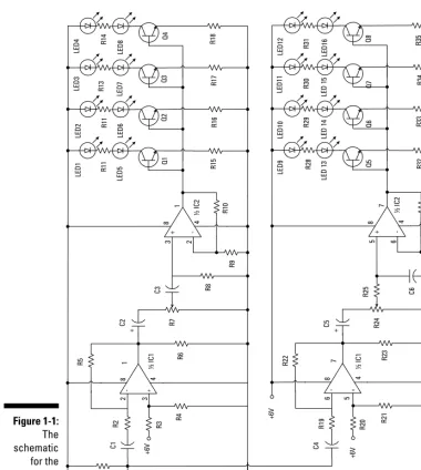
In fact, we have lost ourselves for hours figuring out circuits (this is the elec-tronics equivalent of a jigsaw puzzle, which starts as a drawing, like the one shown in Figure 1-1), wiring the components, and refining the results. You can also, quite literally, amaze your friends with the things you build. And if you go in for electronic gizmos that you can race, scare people with, or use to entertain crowds at parties, you can share the fun with others.
Building things you can actually use
So why, when you can buy an AM radio for $7.95, would you decide to build one yourself with parts that cost $30? That’s a good question. The truth is just about everything you build in the projects included in this book — and most of the cir-cuits floating around on the Internet — is something that you could probably buy in some form somewhere. But where would the challenge be in that?
Here’s why hundreds of thousands of electronics junkies build instead of buying: Because they can. They can make something that grabs music out of the airwaves or sets off a light display or sends a little cart wheeling around the room themselves. We guess this is why people knit sweaters instead of buying them or work on old cars instead of taking them to mechanics. It just feels good to master something on your own.
Parts II, III, and IV of this book are where you can find all these cool projects, divided into categories by what the projects do, such as producing light, sound, or motion.
Some of the things that you build in this book are just for fun, like the danc-ing dolphin light display (Chapter 10). Other thdanc-ings have a practical use: the Couch Pet-ato (Chapter 14) keeps your cat off the furniture when you leave the house, for example.
Besides building gadgets that have a use, in some cases, you can build items more cheaply than you can buy them in the store. You could just end up with projects you can put to work and save a few bucks in the process.
Picking up lots of cool stuff along the way
One of the great things about electronics is that it teaches you about all kinds of things you can use in your life. For example, you discover
⻬How electricity works and how to stay safe when working with it
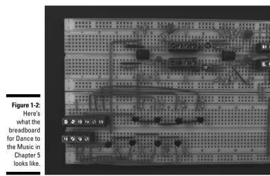
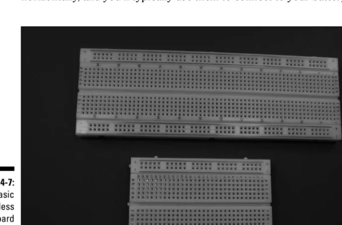
⻬How to read an electronic circuit and build it on a breadboard like the one shown in Figure 1-2
⻬How to use a variety of tools to solder, build, and customize casings to hold your gadgets
⻬How to work with integrated circuits
This book is full of lots of School of Hard Knocks information that might take you years to acquire doing electronics projects on your own; you’ll also pick up lots of wisdom as you work through the projects and try things out for yourself.
What You Need to Get Started
Now that you’re all excited about the benefits of working on electronics projects, you’re probably wondering what this will cost you in dollars and workspace.
How much will it cost?
We tried to keep the cost of the projects in this book to under $100; in many cases, the materials and parts will cost you under $50 or so.
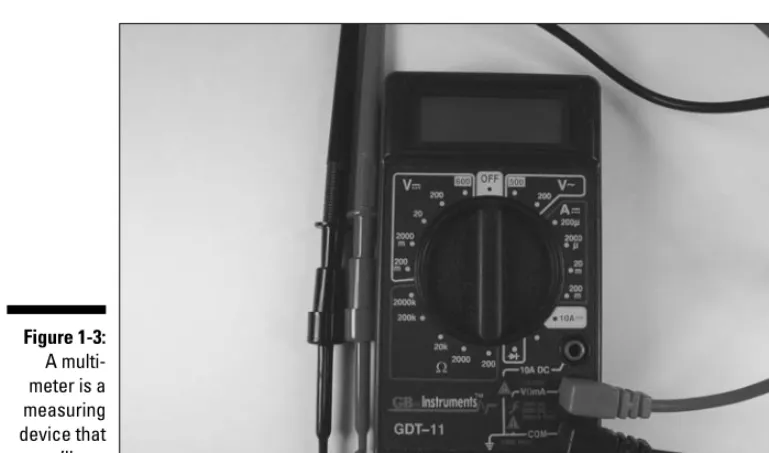
Depending on what you have lying around the house already, you might not have to invest in some of the basic tools, such as pliers or a screwdriver. You will probably have to spend $50 or so for electronics-specific tools and mate-rials such as a soldering iron, solder, and a multimeter like the one shown in Figure 1-3.
If you want to get really fancy, you could spend a couple hundred dollars on fancy testing equipment such an oscilloscope, but you don’t have to have that equipment to get through these projects, by any means.
Of course, in the world outside this book, projects can cost you hundreds of dollars. Like any hobby, you can spend a few bucks to dabble or mortgage your house to get into it in a big way. To get your feet wet in electronics, though, the investment is not that great.
Keep in mind that you can reuse some of the parts of one project (such as a breadboard) in another and cut your electronics budget further.
See Chapter 3 for information about the parts and tools that we recommend you get to build your basic electronics workshop.
Space . . . the final frontier
One thing you do need to leap into the world of electronics projects is space. That doesn’t mean you have to take over your living room and build a fancy workbench. In most cases, a corner of your garage or laundry room stocked Figure 1-3:
with a shelf where you can keep parts and a card table works just fine. We do advise that you find a specific space for your projects.
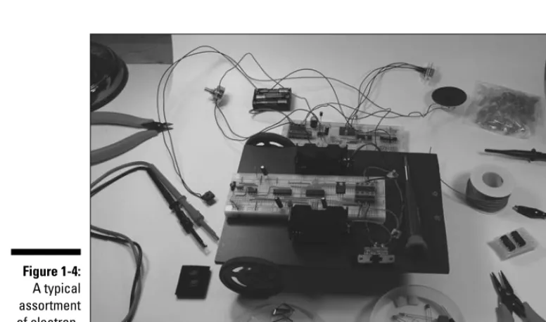
In short order, your workspace will be filled with tools and parts and all kinds of (useful) junk (see Figure 1-4). See Chapter 2 for advice about safety when working with all this stuff. For example, stock your workspace with safety glasses that protect you whenever bits of wire go flying, and find a place where you can keep your soldering iron in a stand so it doesn’t roll into your lap.
We also recommend finding a spot that you can close off if there are others in your household — especially small children or pets — who could topple your work surface or eat tiny electrical parts and do themselves damage. Electronic projects don’t happen in a day, and you might work on a single project over a matter of weeks. If you have a small room with a door to keep others out, great. If not, use your common sense about what you leave out on your work surface overnight.
Chapter 2
Safety First
In This Chapter
䊳Avoiding those nasty shocks
䊳Keeping your electric components safe from static discharge
䊳Working safely with tools
䊳Keeping yourself and your workspace neat and tidy (and safe)
W
e won’t kid you: Electricity deserves your respect.It can shock you, burn you, and even kill you. In this book, we stick with projects that work with AA batteries to limit the potential for serious damage.Still, anytime you work with electronics, there is potential for danger. If these projects get you excited about electronics so that you move on to projects that use bigger jolts of electricity, now is the time to learn the proper respect for electricity and the proper safety precautions when working with electron-ics projects.
In this chapter, you discover what electricity is capable of — and how to keep yourself, electrical components, tools, and those near and dear to you safe.
This is the one must-read chapter in this book. Humor us, and read it from top to bottom, okay?
Avoiding Shocks Like the Plague
Even when the source is removed, some electricity might remain. To be absolutely sure, before you touch anything, test the circuit with your multi-meter. (We talk about how to use a multimeter in Chapter 4.) And don’t take somebody else’s word that the power is off; always check and double-check this yourself!
Don’t work with AC-operated circuits unless you absolutely have to. And if you do, it might not be a bad idea to have a friend nearby who is trained in CPR. Visit www.redcross.orgfor more information about CPR training.
Protecting Electronic Components
from Dreaded Static Discharge
You’re not the only thing in your work area that could suffer from shocks. Static discharge (also referred to as electrostatic discharge; ESD) can do damage to your delicate electrical components. Static discharge is so named because it’s caused by the discharge of electrons from a static charge that hang around in an insulating body, even after the source of those electrons goes away.
Static charge is typically caused by friction. You might trap some electrons in your body as you walk across a carpet, for example. When a static charge is built up on your body, a corresponding voltage difference is built up between your body and a grounded object, such as a doorknob. The zap when you then touch a doorknob is the static discharge: that is, the electrons flowing from you to the doorknob.
What static discharge can do
Metal oxide semiconductor (MOS) devices are cool because they allow inte-grated components to use less power. MOS devices improve circuit design and operation, but that improvement comes at a price. These little guys are VERY sensitive to ESD. One little zap, and they are likely to be history.
MOS devices are found in many integrated circuits (ICs) and transistors. ICs and transistors that use bipolar devices do not have the very thin layers of insulating glass found in MOS devices, so they are less susceptible to damage from static discharge. Resistors, capacitors, diodes, transformers, and coils, on the other hand, aren’t in too much danger from static discharge. Keep static discharge away from your projects just to be safe.
How to guard against ESD
To get rid of static discharge in your electronics workshop, you can do several things, such as wearing anti-static devices and clothing, using static-dissipative floor mats, and grounding your tools.
First, wear an anti-static wrist strap. An anti-static wrist strap is one of the best ways to get rid of ESD. This strap, like the one shown in Figure 2-1, fits snugly on your wrist. You then attach the wire on the strap to earth ground— which is just what it sounds like: namely, the earth beneath your feet.
The cold water pipe on a water heater or under a sink is a good option for earth ground — if the water pipes are metal, that is. Plastic water pipes that you find in some newer construction won’t work. Because the cold water pipe comes up out of the ground, it is therefore grounded (logical, huh?), which works where the hot water pipe usually won’t. Use a clamp to attach a wire to the pipe (earth ground) and run it to your worktable, being sure to Figure 2-1:
tools — from a hot soldering iron to a sharp hacksaw — mandates that you adopt some wise safety habits.
Safe soldering
Soldering poses a few different dangers. (You might use solder to attach various pieces of your electronics project, such as soldering wires onto a speaker, microphone, or switch.) The soldering iron itself (you can see one in Figure 2-2) gets mighty hot. The solder(the material you heat with the iron) gets hot. Occasionally, you even get an air pocket or impurity in solder that can pop as you heat it, splattering a little solder toward your face or onto your arm. To top that off, hot solder produces some nasty fumes.
Soldering itself takes experience to get right. Your best bet is to have some-body who is good at it teach you.
Here are some soldering safety guidelines you should always follow:
⻬Always wear safety glasses when soldering.
⻬Never solder a livecircuit (one that is energized).
⻬Soldering irons come in models that use different wattages. Use the right size soldering iron for your projects, as we discuss in Chapter 3; too much heat could ruin your board or components.
⻬Don’t wear loose-fitting clothing.Loose-fitting clothing and items like scarves or ties can get caught on tools or other items. This could cause you to get a burn, have a fall, or knock a sharp object off your work-bench. Wear comfortable clothing — just not clothing that flaps around. In fact, humor us and tuck in that shirttail right now, okay?
⻬Wear the right fabric.Fabrics made of cotton don’t hold static charges as easily as man-made fibers do. Static discharge can zap electronic components into oblivion. Leave the polyester leisure suit in your closet, and opt for the cotton jeans and shirt instead.
Arming yourself for safety
You should put on certain safety devices — such as ear protection, safety glasses, and leather work gloves — depending on the kind of work you’re doing.
Ear protection makes sense if you’re working with loud noises, such as when running a very loud power tool. With small electronics projects, like the ones in this book, you probably won’t use a very loud piece of equipment. But if you graduate to working on life-size robots, consider your hearing when work-ing with power tools. You can purchase ear muffs, like the ones shown in Figure 2-3, to protect yourself.
As Mom used to say, when they were handing out eyes, you get only two, so take care of them. Safety glasses, like those shown in Figure 2-4, are practically a religion with us. In fact, we’d almost go so far as to say when you enter your Figure 2-3:
workspace, put on safety glasses. That could be going too far, but there are many, many instances when you should wear them: when cutting anything, soldering, clipping wires, and so on. Consider whether safety glasses wouldn’t be a good idea before you do any procedure.
Don’t delude yourself that regular prescription glasses will protect you. They aren’t necessarily made of shatterproof material. Too, they have no protec-tion along the sides.
Direct things that you’re cutting down — toward your workbench — instead of up toward your face. As long as you can make the cut without looking, this can guarantee that flying pieces go away from you and not toward you.
If you’re working a lot with something that generates fumes (anything from paint to solder), consider taking a cue from Zorro and wearing a mask called a respirator(but wear yours over your mouth and nose) that can be found at any hardware store. Respirators are rated for different types of protection, so make sure you get the appropriate one. For example, one type might keep small particles like sawdust out of your mouth, and another might be designed to keep fumes at bay.
Clean up your stuff!
Keeping your workspace neat, including minimizing strung-out cords that could trip you up, is important in preventing accidents.
A cluttered work surface makes it hard to see what you’re reaching for. You might reach over to grab a plastic box, only to come up with a mini hacksaw in your palm (ouch!).
Pick up small pieces of cut wire or loose screws and nails. Not only could you step on one and cut yourself if you decide to work barefoot someday (not something we recommend), but a pet or child could pick up such small items and decide they would be tasty.
Keeping kids and pets out of your space
Besides keeping your space neat, you should also keep your space off-limits to the smaller members of your household: namely, kids and pets. Even if you put away all sharp tools religiously and make sure that any power source is disconnected from breadboards, small hands (or paws) are made for mischief.
If you can, lock your workspace when you’re not in it. If you can’t (maybe because your workspace is a corner of your den), lock up your electronic project tools, components, and works in progress in a box or cabinet.
Electronics and alcohol don’t mix
Okay, this probably goes without saying, but don’t work around electronics if you’ve had a drink (or two or three). Alcohol slows your brain
Chapter 3
Assembling Your Electronics
Arsenal
In This Chapter
䊳Gathering the right tools for the job
䊳Collecting electronic components to make projects run
䊳Finding what you need to build what surrounds your project
䊳Building circuits on breadboards
W
hen you meet somebody who has had a hobby for a few years, he or she usually has a well-stocked arsenal of materials and tools for the task at hand. Knitters have drawers full of wool; stamp collectors have tweez-ers and scrapbooks; and electronics people have drawtweez-ers full of switches, resistors, capacitors, integrated circuits, and transistors.In this chapter, we walk you through the typical items that you need to work with for electronics projects. We introduce you to just about all the tools and components and building blocks that you use in the projects in this book. Whether you buy some now or wait until you need them, by the time you finish this chapter, you will be familiar with the most common tools of the electronics trade.
Tool Time
Soldering prerequisites
If you’ve ever used wax to seal an envelope, you understand the basic premise of soldering. Take a material (in this case, solder; pronounced sod-der) and heat it so that it melts onto items, such as two wires you have twisted together to make a physical connection. When the solder cools, you have a seal or joint that makes an electrical connection between the items.
Soldering requires that you get your hands on a few basic items:
⻬Soldering iron:See an example of one in Figure 3-1.
Get one rated at about 30 watts, preferably one for which you can buy dif-ferent size tips so you can work on difdif-ferent types of projects. And make sure to get an iron with a three-prong plug so that it will be grounded.
⻬Tips:Large tips can be chisel-shaped and about 1⁄
8" wide; small tips can have a cone shape with a radius at the tip of only 1⁄
64". Most soldering irons don’t specify the tip sizes that are supplied with the iron. For most electronics work, we suggest you just find one described as a fine tip at a electronics supplier. If you’re ordering a replacement tip, a 3⁄
64" cone shape is a good size for general use. If you’re soldering circuit boards, you might try a 1⁄
64" cone-shaped tip. Figure 3-1 shows a soldering iron with a collection of different tip sizes and shapes.
Figure 3-1: A collection of tips, a soldering iron, and
For the projects in this book, an assortment of drill bits that includes bits up to 1⁄
2" in diameter (the shank of the 1⁄2" bit should be 3⁄8") and a cordless 3⁄8" drill are probably your best bet.
Hacking away with saws
From the magician who saws his assistant in half to the saw you use to cut off a dead tree branch, these tools are handy to trim off excess bits.
Here are the kinds of saws you might need when building electronics projects, especially to build the boxes or boards that contain the electronics brains or trim off little bits of plastic. See Figure 3-3 to view an assortment of saws:
⻬A coping sawallows you to cut openings in a sheet or box of plastic or wood. For example, you might use this saw to cut a hole in a box to insert a speaker.
⻬A hacksawor a conventional hand sawcan be used to make straight cuts in sheets of plastic or wood or to cut plastic pipes or wooden boards to the desired length.
⻬A mini hacksawis useful when you don’t have enough room to work with a full-sized saw. This can be common with electronics projects. Figure 3-2:
A 3⁄
8" drill
Hacksaws and coping saws have replaceable blades; you can find new blades at hardware stores. When you buy a new blade, check the package to see what material it is intended to cut. Manufactures make blades with different pitches(that is, spacing of the teeth) for cutting different materials, such as metal versus wood or plastic.
Power saws go by names such as circular saws, chop saws, jigsaws, table saws, and band saws. You don’t need to go out and buy this type of equip-ment for the type of projects included in this book. However, if you’re dying to work with one of these higher-powered saws and someone offers to loan you one, please make sure you know how to operate it safely. It’s best to have all your fingers and toes accounted for to work on electronics!
Garden variety tools: Pliers, screwdrivers,
wire strippers, and more
This is the category of tools that you’re most likely to have floating around your garage or household toolkit. Take an inventory of your toolkit. (We’ll
Hacksaw
Coping saw
Mini hacksaw
wait.) If you’re missing any of the tools in this list, it’s probably worth going to your hardware store and picking them up.
⻬Precision screwdrivers:This includes both straight and Phillips head (the one with the cross shape at the tip).
⻬Mini or hobby needlenose pliers:These are useful for bending wires to various shapes for breadboarding; you also use them to insert wires and components in the holes of the boards.
⻬Standard sized needlenose pliers:These are useful for tasks where you need to apply more strength than mini needlenose pliers can handle. You can see both standard-sized needlenose pliers and the smaller ver-sion in Figure 3-4.
⻬A small pair of wire cutters:These are useful for clipping wires in close quarters, such as above a solder joint. The standard size of wire clippers you find at hardware stores is so large that you might have trouble clip-ping the wire with enough precision. You can see the smaller version in Figure 3-4.
Precision screwdriver
Wire strippers
Mini needlenose pliers
6" needlenose pliers
Small wire cutters
Table 3-1
Capacitor Values
Marking Value
101 0.0001 µF
102 0.001 µF
103 0.01 µF
471 0.00047 µF
472 0.0047 µF
473 0.047 µF
474 0.47 µF
For much more detail about various types of capacitors and how to read capacitor values, we recommend that you go out and buy Electronics For Dummies,by Gordon McComb and our own Earl Boysen (Wiley).
A final capacitor distinction that we have to make is variable versus fixed. All the capacitors we talked about so far are fixed,meaning they have a set value you can’t adjust. However, variable capacitors can by adjusted by various meth-ods. We use a variable capacitor, for example, in Chapter 8 for tuning a radio.
Transistors
Transistors are the darlings of the electronics world. Transistors amplify a signal or voltage, or switch voltage on or off. The really amazing thing about transistors is how tiny they are: Before the advent of transistors, people used vacuum tubes to perform the same function, and a vacuum tube is huge in comparison. Transistors also use a lot less power.
Transistors come in
⻬NPN (negative/positive/negative):You turn on NPN transistors by apply-ing positive voltage; they start to turn on when you apply about 0.7 volts.
We use NPN transistors throughout this book because it’s more straight-forward to apply a positive voltage to get things working.
⻬PNP (positive/negative/positive):You turn off PNP transistors by apply-ing positive voltage; they turn on when you apply negative voltages or voltages near ground.
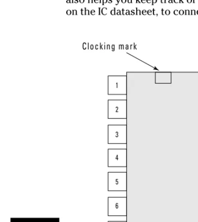
Transistors have three leads: the emitter, base, and collector. In Chapter 4, we show you how to read schematics so you can figure out where to connect each pin. For each transistor you use, check the datasheet (which contains a drawing, called a pinout) to determine which pin is which.
ICs
Integrated circuits — commonly known as ICs— are like social directors for components: They gather lots of other components in a single location
TO-92 TO-39 T0-220
(shuffleboard optional). ICs typically contain a number of transistors, resis-tors, and capacitors connected on a silicon chip to make a functional circuit in one small package.
ICs, as well as some other electrical components, can be susceptible to elec-trostatic discharge (in other words, zapping). For that reason, be sure to also get yourself an anti-static wrist strap (as we discuss in Chapter 2) for your electronics workshop.
ICs come in many packages
Manufacturers make ICs in many types of packages or containers. (A whole valley in California is dedicated to this type of thing.) The type of package that you use either in a breadboard or a circuit board is a dual inline package (DIP). A DIP is made up of plastic that encapsulates a silicon chip, with a row of metal leads running on either side of the plastic. You insert these leads into the contact holes in a breadboard and connect components on the breadboard with the circuitry on the silicon chip. (See the later section, “Breadboard Basics,” for more about this process.)
DIP ICs are identified by the number of leads they have, such as 8-pin DIP, 14-pin DIP, 16-pin DIP, 18-pin DIP, and so on. Figure 3-6 shows a few common DIP ICs.
outgoing wires. When the switch is in one position, the incoming wire is connected to the first of the outgoing wires. When the switch is in the other position, the incoming wire is connected to the second of the out-going wires. (If you have a different need and this is the type of switch you happen to have in your parts bin, you can use just two lugs to make it work as an SPST.)
⻬DPDT (double-pole, double-throw):This kind of switch has six lugs to which you can solder wires. These lugs can be attached to two incoming wires and four outgoing wires. When you flip this switch, you simply switch each incoming wire between two of the outgoing wires. We use this type of switch in a relay in Chapter 13 to switch control of the motors from one type of sensor to another.
As if switches didn’t have enough names, they are also referred to by the method used to change their state from open to closed. See Figure 3-8 to see the different types.
⻬Toggle switch:This switch gets its name from the fact that you flip a lever to turn it on and flip it back to turn it off.
⻬Pushbutton on/off switch:Every time you push this button, it changes from on to off or vice versa.
⻬Momentary pushbutton switch:Pushing this switch is what changes its state, but only for the moment! These are also classified by whether they are normally open (NO)or normally closed (NC).For example, a momen-tary normally open switch is closed only while you hold the pushbutton down. When you release the button, it goes back to its normal — open — state.
⻬Tactile switch:This is a type of momentary pushbutton switch. Tactile switches are rated by the amount of force that is needed to push the button and are often flat so that they can be easily inserted somewhere without protruding (like how we insert them into the hands of a puppet in Chapter 7).
⻬Slide switch:Logically, this switch operates when you slide a knob to change it from on to off or vice versa.
⻬Relays:These switches are operated by a voltage rather than by pushing a switch. This makes them very useful for turning on or off a component, such as a light or motor, through a remote control or by voltage gener-ated by a sensor. We control relays with both methods in Chapter 13.
Toggle switch Pushbutton switch Tactile switch
Slide switch Relay switch
Let there be light: Light emitting diodes
A diodesends out light when you pass an electric current through it. LEDs, which we use quite a bit in the projects in this book, are similar to the tiny, twinkly lights you use to decorate a Christmas tree, and they come in a vari-ety of colors, such as red, orange, yellow, green, blue, and white. Blue and white LEDs are a lot more expensive, so you don’t see them used that often in this book. (We’re thrifty!)
LED color isn’t controlled by the plastic that surrounds the light. Rather, the semiconductor material used in the LED determines the color. The plastic surrounding the semiconductor material can be clear or treated so that it dif-fuses the light.
In addition, you can get LEDs in several sizes and shapes. The standard LED, which is a cylinder with a diameter of 5mm, is referred to as T-1 3⁄
4.
If you don’t connect LEDs the right way, you could wait forever to see the light. Connect the longer of the two leads to the positive voltage and the shorter of the two leads to ground or the more negative voltage.
Speaking up about speakers
Everybody knows what a speaker is: There’s one on your DVD player, your computer, your iPod — you name it! Most speakers contain a permanent magnet, an electromagnet, and a cone-shaped device from which the sounds emerge (see Figure 3-9).
Permanent magnet
Electromagnet
Cone
Most buzzers give off sound in the 2–4 kHz range. Buzzers aren’t very dis-criminating when it comes to voltage: Their ratings are approximate, meaning that a 12V buzzer is absolutely happy to work with a 9V power supply.
Buzzers have two leads, and you have to connect a buzzers the right way round. The red lead is always positive (+).
The Nuts and Bolts of Building Materials
A pure electronics project might just consist of a breadboard containing com-ponents and wires. In most cases, though, you’ll also want to create some sort of container or chassis to hold the project. For example, if you build a simple radio, you might put the guts of it in a box and drill holes to place the dials and speaker.You can buy ready-made boxes or other containers and make them work for your project. You can also build your own out of various materials.
Plastic
ABS (please don’t ask what this acronym means; we could tell you, but you couldn’t pronounce it) plastic boxes are available from most electronics sup-pliers. These are lightweight, sturdy, waterproof, and handy for housing your gadgets. We use a plastic box in Chapter 11 to house a remote control.
The plus with plastic boxes is that components such as switches are designed to be mounted on boxes or panels with thin walls. Therefore, mounting these components on these plastic boxes is often easier than on wooden boxes.
The downside is that cutting clean openings in plastic is harder than in wood — for example, to insert speakers.
Wood
To mount components such as speakers, you need screws and nuts. The parts lists in our project chapters tell you what size screws and nuts to get; we’re betting you have some of these in that leftover cake tin in your garage gather-ing dust, but you can buy what you need for pennies in any hardware store.
We find that 6-32 screws fit many mounting holes.
Holding down wires
Wire clips are very useful for organizing wires that you affix to your project container. These generally have an adhesive backing on the base that you use to attach them to a surface. Then you slip the wires into the clip, and they are nicely held in place. (We use RadioShack part #287-1668.)
Cable ties can also be useful when you want to run wires along something without a flat surface, like a wooden dowel.
Breadboard Basics
A breadboardis a rectangular plastic box filled with holes, which have contacts in which you can insert electronic components and wires. A breadboard is what you use to string together a temporary version of your circuit. You don’t have to solder wires or anything else; instead, you poke your components and wires into the little contact holes arranged in rows and connected by lines of metal; then you can connect your components together with wires to form your circuit.
The nice thing about breadboards is that you can change your mind and replace or rearrange components as you like. You typically create an elec-tronics project on a breadboard to make sure that everything works. If it’s a project you wish to save, you can create a more permanent version. We use breadboarded versions of circuits exclusively in this book.
If you want to create a permanent version of your circuit, you need to create a soldered or printed circuit board; see the sidebar, “Printed circuit boards,” to find out how to go about that.
Figure 3-11: A large circuit built on multiple breadboards hooked together. Figure 3-10: Two bread-boards, one with 830 contact holes and one with 400 contact
Wires pull it all together
When you place components in a breadboard, you don’t get much action until you connect those components with wire. Wire used in electronics is copper
Printed circuit boards
If you create a circuit on a breadboard and decide that it’s worthy of immortality, you can make it permanent by soldering components in place on a printed circuit board. To do this, you have to get your hands on a universal printed circuit board. This is much like a breadboard except that you can solder all the connections you’ve made to keep them around.
A universal printed circuit board has rows of individual holes throughout the board with copper pads around each hole and metal lines connecting the holes in each row, like in a breadboard. You mount parts on the face of the board and then pass leads through holes to the
components. You can solder the leads to the copper pads on the bottom of the board. Universal printed circuit boards are available in a variety of patterns of contact holes and metal lines. The figure here shows one we like because there are rows on either side that accommodate discrete components handily. This circuit board is made by One Pass, Inc. (www.onepassinc.com).
Connectors
Finally, terminal blocks are used to connect wires from components such as speakers, motors, and microphones to the breadboard. A terminal blockis a small block of plastic that you mount on a breadboard. You insert the wires into the terminal block through a hole in the block and then tighten screws to hold the wire securely.
Chapter 4
Running Down the
Skills You Need
In This Chapter
䊳Discovering schematics
䊳Assembling little bits and pieces on breadboards
䊳Spiffing up your soldering skills
䊳Troubleshooting problems with a multimeter
䊳Working with the boxes that enclose your projects
Y
ou need three key things to build an electronics project: materials, a workspace, and certain skills that help you assemble the materials into something that moves, beeps, lights up, or otherwise makes itself electronically known to the world. (You also need time, but we’ll leave that to you to find.)In Chapter 3, we talk about organizing your materials and workspace. In this chapter, we address the third element — the skills that you need to read cir-cuit designs, build, and test electronics projects. This chapter provides an overview of these skills; for more comprehensive explanations, check out Electronics For Dummies,by Gordon McComb and Earl Boysen (Wiley).
It’s Symbolic: Reading a Schematic
A schematicis your blueprint for building an electronics project. A blueprint for building a house uses various symbols to represent elements, such as doors, and lines to show walls. Instead of doors and walls, the symbols and lines in a schematic represent components such as transistors, integrated cir-cuits (ICs), and resistors as well as the wires that connect them.
Schematics help you understand how a particular electronics project works as well as how to build it. You can build the circuit on a breadboard (more on that in the upcoming section, “Breadboarding”) by inserting the components and making the connections on the board that are indicated by the schematic.
Perusing a simple schematic
An example of a very simple schematic shows a battery, one electronic com-ponent, and the wires connecting them. Figure 4-1 shows a schematic that contains a 1.5 volt battery, a wire from the positive side of the battery (+V) connecting it to one of the leads on an LED, and a wire connecting the other lead of the LED to the negative side of the battery. With both wires connected, current flows from one terminal of the battery through the LED, making it light up, and back to the other terminal of the battery. (If the LED is connected to only one battery terminal, no current flows, and the LED will not light up.)
Some circuits use too many components for the schematic to show the wire connecting every component to the battery. In those cases, we use a conven-ient symbol for a voltage source to represent the positive side of the battery and a ground symbol to represent the negative side of the battery, as shown in Figure 4-2. This is same circuit as the preceding figure with a voltage source symbol and ground symbol representing connections to the battery. These symbols are also used in applications where a metal chassis is used as ground and a power supply is used to supply voltage.
You can read more about connecting to +V and ground in the later section, “The anatomy of a breadboard.”
+
-
1.5V LED1Interconnectionsamong components (how wires are connected to move elec-tricity from one component to another) in a circuit are made with wires or bits of copper placed on a breadboard. A schematic won’t usually specify which kind of connection you are using, only that a connection exists. Figure 4-3 shows a few methods of representing interconnections.
UNKNOWN
Unconnected Unconnected Connected Connected
Figure 4-3: How con-nections and non-connections are repre-sented in schematics.
1.5V
LED1 Figure 4-2:
The anatomy of a breadboard
The breadboard itself is a plastic board with strips of metal running under-neath and holes in the top. You slot the little wire legs that sprout from com-ponents and also the connecting wires into these holes, which contain metal channels called contacts.The metal strips that run underneath connect the items you plug into the holes to each other and the battery.
Breadboards come in various sizes; however, no matter what the size, the top and bottom rows of contacts on the breadboard (see Figure 4-7) are linked horizontally, and you’ll typically use them to connect to your battery.
How to figure out what size breadboard to get? Some have as many as 3,200 contact points! But don’t overdo. For the projects in this book, we used boards with 400 contact points for small circuits and 830 contact points for medium circuits; for our large circuits, we hooked two boards together with the handy ridges and notches on the sides of the boards.
Notice the + and – (negative) signs on the breadboard. The positive battery terminal is connected to the rows with the + sign; these rows are often referred to as the +V bus.The negative battery terminal is connected to the rows with the – sign; these rows are often referred to as the ground bus.Because the +V bus and the ground bus run the entire length of the board on both sides, you need to use only a short piece of wire to reach a +V or ground bus from any-where on the breadboard.
2. Measure how long of a wire you need to make each connection.
3. Strip off 1⁄4" of insulation from each end.
Better yet, buy prestripped wires.
4. Bend the bare wire at a right angle.
5. Insert the wire into a hole in the board.
The schematic shown earlier in Figure 4-6 is shown translated onto a bread-board in Figure 4-10. You don’t see the potentiometer, microphone, battery, switch, or speaker on the breadboard because these are connected through wires attached to the five terminal blocks (TB). The sole purpose of a termi-nal blockis to provide a place where you can attach wires to your circuit board by inserting them into holes and using a screw to clamp them down.
Notice that we inserted a lead from C2 into a contact in the same row as Pin 1 of IC1, thereby making electrical contact. We ran a wire from the same row as the other lead of C2 around IC1 to Pin 8 of IC1. This produces a lot neater board than you get when you loop wires over the IC.
Notice also how all the wires are flat on the breadboard. We cut them all to the length required so they didn’t have excess wire poking up in the air.
We measured the resistor leads so that we had enough length to cross the distance between the contacts and still have about 1⁄
4" more on either side to bend down and insert in the breadboard holes.
Stranded wire
Solid wire
Insulation Single wire
Insulation Several fine wires
We bent the wires on the ceramic capacitors at a 45° angle so that the face of the capacitor is visible. That way, you can easily read the value of the capaci-tor on the board.
We cut the leads of the electrolytic capacitors to about 3⁄
4" to minimize how far they stick up in the air.
When you use a breadboard, you can use and reuse components for different projects. However, be aware that the little contact wires on components can break off easily. If you remove ICs, use an IC extractor or the flat end of a small screwdriver to pry the IC up at both ends, or you will damage it and probably end up tossing it. The leads on ICs aren’t designed to be bent more than once or twice, or they will break off.
Soldering Your Circuit Board
Electronics projects involve a lot of little bits called components(think tran-sistors and capacitors, for example) and wire, and items like microphones and light bulbs and such. In many instances, you have to solder some of
Battery and S1 TB
C3
C4 C2 IC1 R1
Headphone/speaker TB Potentiometer TB Microphone TB
C1
C5 R3
these things together to provide an electrical connection between them. Solderis a metal material that you melt and apply to two items; when it cools, it forms a joint that holds items together and forms an electrical connection.
So why do you need to solder if you use solderless breadboards? Although we chose to not have you make circuits permanent by soldering them for the purpose of the projects in this book, we do ask you to solder wires to switches and microphones and such, so this is definitely something you need to be able to do.
Soldering perfect joints is an acquired skill — one that you just get better at with practice. Here are some valuable tips for getting started.
Please, please read the several safety precautions about soldering in Chapter 2. You’re playing around with 700°F temperatures here, and we don’t want you to get hurt!
Using a soldering iron
A soldering iron(sometimes called a soldering pencil) is like a wand that gets very, very hot so that when you touch it to the solder, it melts it. You can find a variety of soldering iron models (see an example in Figure 4-11), which will vary in price based on features, such as those we discuss in Chapter 3.
⻬Bend before you solder, Part 2.Before soldering a wire to a component that has presoldered flat contact pads, do the following:
1. Bend the end of the wire at a 45° angle.
2. Heat the end of the wire.
3. Apply a light solder coating to the wire.
4. Press the wire onto the contact pad with the soldering iron.
5. Hold down the wire with the soldering iron until the solder on the pad melts.
6. Remove the iron and hold the wire on the pad with your other hand until the solder cools. (You should hold the wire several inches from the solder joint so your fingers don’t get hot.)
Make sure that the component you’re soldering is kept steady. (Read about third-hand clamps in the next section for help with this.)
Figure 4-14 shows a microphone cartridge wire soldered with this technique.
Soldering extras
Your soldering iron and solder are the main tools you need to make soldered joints. However, a few accessories will make your soldering life easier. These include
⻬Sponge:You use a damp (not dripping) sponge to wipe the tip of your soldering iron clean before soldering each component.
⻬Tip cleaner:If you don’t keep the iron’s tip clean, it might actually repel solder — making it bead up and staying away from where you want it to go. When the tip is too grungy to be cleaned by simply wiping it on the damp sponge, use a tip cleaner paste to chemically clean it.
⻬Solder wick:Sometimes you have to desolder a bad joint and then resol-der it. To help remove the bad solresol-der, you can use a solder wick,which is a flat, braided piece of copper that soaks up solder.
⻬Third-hand clamp:There are fancy clamps you can buy called third-hand clamps to hold components while you solder them. Personally, we just use a vice and an alligator clip; they do just fine!
Measuring Stuff with a Multimeter
A multimeter(see Figure 4-15) is a testing device that, um, tests multiple things, including resistance, voltage, and current. Using certain multimeter models, you can test to be sure that components — such as diodes, capaci-tors, and transistors — function properly. You can also troubleshoot your cir-cuit to see where current is failing and pinpoint the problem spot.
You don’t have to break into your piggy bank to buy a multimeter. You can find them for about $10; if you want fancy features, you can spend over $100. Find a model whose price you like and then splurge on the next higher-priced model. You will use a multimeter all the time. Trust us: It’s worth a few extra bucks for a better model. See Chapter 3 for more information about multi-meter features.
How a multimeter works
A multimeter has a set of leads: a black one and a red one. You attach these leads to the component or portion of the circuit that you’re testing, and a dig-ital readout provides the results. You adjust a knob to set the test you wish to perform such as resistance, voltage, or current as well as the range to test.
Note:Some multimeters have an auto-ranging feature that saves you the trou-ble of setting the range.
get old, the voltage drops. If you get less than 5 volts from a 4-battery pack, it’s time to get new batteries.
When a circuit doesn’t work, one of the first things to check is the voltage between the +V bus and the ground bus of the breadboard. Here’s how:
1. Strip both ends of a 3" piece of 22 gauge wire.
2. Clip one end of each wire to one of your test leads.
3. Slip the free end of the wire attached to your red test lead into any contact on the +V bus.
4. Slip the free end of the wire attached to your black test lead into any contact on the ground bus.
Although you might not get a reading of the full 6 volts because of drain on the battery from the circuit, you should get a reading above 3.5 volts.
If you get a reading close to 0 (zero) volts, check to make sure that your battery pack and the wires from the battery pack terminal block are con-nected properly.
Working with the Boxes that
Contain Your Projects
In most cases, you’ll want to put the breadboard on which you build your cir-cuit into some kind of container. A container can make toting around your breadboard easier, help prevent little bits from falling off, and make your pro-ject look better. You might also want to add mechanisms for controlling your circuit in a box. For example, you might operate a remote control device by disconnecting and connecting wires on a breadboard, but wouldn’t it be easier to put the breadboard in a box and then add switches and buttons you can use to make it work?
In this section, we give you some advice about basic skills you need to work with these containers for your projects.
Working with boxes
@Spy
Some components, such as speakers or buzzers, have holes in flanges that you can use to secure the component to the wall of the box with screws. Use the flange holes as a template to mark the locations to drill holes.
Some components are meant to be panel-mounted but don’t have threads. For example, in Chapter 11, we use a two-piece, LED panel-mount socket in which one part of the socket slides through the hole and onto the other half and snaps in place, securing the LED.
In some cases, you have to mount microphone cartridges that don’t come with threads or snap sockets in the walls of boxes. Simply drill a hole that’s just big enough in diameter to slip the cartridge in with a snug fit. If you’re using a wooden box, the wall of the box should be thick enough to secure the microphone cartridge. If you’re using a plastic box, you’ll probably need to secure the microphone cartridge with glue.
Sticking things on the box
If you use screws to attach a component to a wooden box and you want to put something else over the screw head, use a flathead screw, as shown in Figure 4-16. When you don’t need to keep the surface flush, panhead screws are just fine.
@Spy
For items with flat surfaces such as breadboards or battery packs, Velcro or similar materials are useful to secure them in your box. However, if you remove breadboards that you have secured in a box with Velcro, be careful. Breadboards have a thin sheet of plastic or paper on the back that can peel off if you’re not careful.
You can make custom mounts out of metal bars, screws, and nuts, as shown in Figure 4-17, which shows also how we mount the motors in Chapter 13.
Figure 4-17: Make a custom mount with a metal bar and screws.
When stranded wire works
If you’re connecting a component in the lid ofyour box to a terminal block on the breadboard in the bottom of the box, that wire will be bent back into the box when you close the lid. In this case, it’s best to use stranded wire, which is more flexible than solid wire. (Refer to Figure 4-9 for a comparison.)
@Spy
You can also use wooden dowels and cable ties as we did to mount the micro-phone in Chapter 6 (see Figures 4-18 and 4-19).
Figure 4-19: With the microphone cartridge
@Spy
You can use wire clips to secure wires to the side of boxes so they are out of the way as you work, as shown in Figure 4-20.
@Spy
Part II
@Spy
In this part . . .
W
e thought we’d start you working on projects that provide a bang, so this first set of projects is all about making noise. The chapters in this part set lights dancing to music and help you pick up sounds at a dis-tance with a parabolic microphone. You also get to build your own AM radio.@Spy
Chapter 5
Making Light Dance to the Music
In This Chapter
䊳Taking a peek at the schematic
䊳Checking off the parts list
䊳Breadboarding the circuit
䊳Calibrating your frequencies
䊳Lighting up to music
M
usic hath charms to soothe the savage breast, as the saying goes. Whether you feel particularly savage or not, if you enjoy listening to all kinds of music, you’ll enjoy this project. Here, we combine light and sound in an interesting way: We show you how to set up two rows of lights that illu-minate to different frequencies of sound. When you put on a rowdy piece of music — say, swing or reggae — the lights dance all around. Every piece of music has its own, unique effect.We chose to arrange our lights like notes on a music staff, but you could put them in any arrangement you like. By working through this fun project, you get to know more about frequency filters, operational amplifiers, and how music can make things light up and get your toes tapping.
The Big Picture: Project Overview
@Spy
Here’s the overview of what you’ll be up to in the Dance to the Music project. You will
⻬Put together an electronic circuit to turn on the LEDs in response to sounds.
Half of the LEDs will flash to high-frequency sounds, and the other half will flash to low-frequency sounds.
⻬Create a template for the musical notes; then place the template on the box and drill holes in the top of a wooden box for the LEDs. ⻬Wire two groups of LEDs and resistors.
⻬Turn on the juice (that is, pop in the batteries and flip the switch), and then turn on some music.
The circuit sends current to each group of LEDs in response to the music.
⻬Get dancing yourself. This one’s infectious! Figure 5-1:
The following sections explore the schematic elements in detail.
Fancy Footwork: Exploring the
Dance to the Music Circuit
To make your musical score light up in response to the music, you need to make a circuit that uses a microphone, as well as two operational amplifier ICs in combination with some resistors, capacitors, and transistors. Working together, these control which group of LEDs lights up to a particular frequency of music.
Here’s the overview of the schematic elements that you use to control your project:
⻬The circuit starts with an electret microphone, which transforms sound into electrical signals.
⻬R1 connects the microphone to positive voltage and supplies about 4.5 volts required by the microphone to function.
⻬C1 and C2 are capacitors that block the DC voltage on the input signal and allow the AC signal to pass.
⻬At this point, the circuit splits: The signal processed by the upper half of the circuit powers the LEDs blinking in response to high-frequency sound; the signal flowing through the lower half of the circuit powers the LEDs blinking in response to low-frequency sound.
⻬IC1 is an operational amplifier (op amp) that amplifies the signal from the microphone. The IC contains two op amps; one half of IC1 is used in the upper circuit, and one half of IC1 is used in the lower circuit.
⻬R2 and R5 in the upper circuit and R19and R22in the lower circuit set the gain for each side of IC1. Because R5 is 50 times R2, a signal processed by the op amp is amplified approximately 50 times.
Gainis the amplitude of the voltage out divided by the amplitude of the voltage in: in other words, how much more juice goes out than comes in.
The circuit won’t mean a thing if you don’t set up the lights for it to con-trol. That’s where the two groups of LEDs and resistors come in. They include
•LED1–LED8 to light the display for the high-frequency circuit and LED9–LED18to light the display for the low-frequency circuit.
•R11–R18 in the upper circuit and R28–R35in the lower circuit are resistors, that in series with LEDs, limit the current running through the LEDs to approximately 10 milliamps.
Building Alert: Construction Issues
Behind the musical score, we drew on the box that holds the circuit, and all the resistors and LED leads are soldered together. To make sure that leads that get bent and touch don’t cause a short, they need to be protected. Rather than using electrical tape, we use liquid electrical tape to coat the exposed leads.
Wires run between the circuit board resting on the bottom of the box and the LEDs that you insert in the top of the box. Be sure to cut your wires long enough so that when you open the box (which moves the LEDs in the top far-ther away from the circuit in the bottom of the box) that you don’t rip out the wires. Also be careful that you leave room to tuck those long wires inside the box when closed so they don’t poke out the sides or get caught in the hinges. This is one case when stranded wires work better than solid wires because they are more flexible.
Perusing the Parts List
It’s off to your nearest electronics store or online vendor for those electronic parts you use to build the circuit and assemble the box that contains all those LEDs.
The circuit that transforms music into your dancing light show involves the following parts, several of which are shown in Figure 5-3:
⻬2.2 kohm resistor (R1)
⻬Eight 100 ohm resistors (R15–R18, R32–R35) ⻬Two 10 kohm potentiometers (R7, R24) ⻬Four 47 kohm resistors (R3, R4, R20, R21) ⻬Two 100 kohm resistors (R5, R22)
⻬Two 2 kohm resistors (R2, R19) ⻬Two 5 kohm resistors