Volume 2009, Article ID 786291,11pages doi:10.1155/2009/786291
Research Article
Time Domain Equalizer Design Using Bit Error Rate
Minimization for UWB Systems
Syed Imtiaz Husain,
1Jinhong Yuan,
1Jian Zhang,
2, 3and R. K. Martin
41School of Electrical Engineering and Telecommunications, University of New South Wales, Sydney, NSW 2052, Australia 2Australian National University, Canberra, ACT 0200, Australia
3Canberra Research Laboratories, National ICT Australia (NICTA), Canberra, ACT 2601, Australia 4The Air Force Institute of Technology, Kettering, OH-45433, USA
Correspondence should be addressed to Syed Imtiaz Husain,[email protected]
Received 28 January 2009; Accepted 27 March 2009
Recommended by Steve McLaughlin
Ultra-wideband (UWB) communication systems occupy huge bandwidths with very low power spectral densities. This feature makes the UWB channels highly rich in resolvable multipaths. To exploit the temporal diversity, the receiver is commonly implemented through a Rake. The aim to capture enough signal energy to maintain an acceptable output signal-to-noise ratio (SNR) dictates a very complicated Rake structure with a large number of fingers. Channel shortening or time domain equalizer (TEQ) can simplify the Rake receiver design by reducing the number of significant taps in the effective channel. In this paper, we first derive the bit error rate (BER) of a multiuser and multipath UWB system in the presence of a TEQ at the receiver front end. This BER is then written in a form suitable for traditional optimization. We then present a TEQ design which minimizes the BER of the system to perform efficient channel shortening. The performance of the proposed algorithm is compared with some generic TEQ designs and other Rake structures in UWB channels. It is shown that the proposed algorithm maintains a lower BER along with efficiently shortening the channel.
Copyright © 2009 Syed Imtiaz Husain et al. This is an open access article distributed under the Creative Commons Attribution License, which permits unrestricted use, distribution, and reproduction in any medium, provided the original work is properly cited.
1. Introduction
Channel shortening is an equalization technique which forces the effective channel impulse response (combined channel and equalizer) to be confined within a desired temporal window. Channel shortening or time domain equalizers (TEQs) have been used in communication systems since the early 1970s [1–4]. The earlier usage of TEQs was to reduce the number of states in sequence estimation and thus simplify the process. TEQ designs were reinvestigated in the 1990s to mitigate the intersymbol interference (ISI) produced due to inadequate cyclic prefix (CP) in multicarrier modulation (MCM) systems [5–10]. Each of these designs uses a particular cost function, which may be general or system specific, to perform efficient channel shortening. TEQ has also been proposed to simplify multiuser detection in a large set of users [11]. The TEQ in this case eliminates some users’ signals to effectively reduce the size of the user set.
Rake can be implemented with a smaller number of fingers. This not only simplifies the receiver front end but also the rest of the signal processing and the manufacturing cost involved. Hence, channel shortening in UWB receivers can help in designing a simple and cost effective struc-ture.
UWB communications systems are entirely different from the MCM systems for which a TEQ is commonly proposed. First of all, UWB is a wireless scenario with extremely dense multipath channels. Standard UWB chan-nel models, namely CM1 to CM4 [17], are much more complex than those used in wired line MCM systems, for example, carrier serving area (CSA) loops in asymmetric digital subscriber line (ADSL). Furthermore, to make the UWB receiver design practically simple, a large number of channel taps must be eliminated. This makes the shortened channel window very much smaller than the suppressed channel. Hence, the problem of TEQ design appears in its extreme form. In UWB systems, channel energy capture is crucial to maintain a good output SNR, whereas in most of the existing TEQ designs, except [7, 8, 18], channel delay spread or bit rate is more critical. Also, none of the existing designs considers a multiuser system. The TEQs presented in [13, 14] are very simple to implement but have moderate performance. Whereas the designs presented in [15, 16] perform relatively better but exploit some UWB channel specific parameters. Again, none of them is developed for a multiuser environment. Recently, a TEQ design was proposed which directly minimizes the bit error rate (BER) of cyclic prefixed-based systems [18]. Since traditional UWB systems do not use cyclic prefix and are baseband, we need to derive the BER of a multiuser system in the presence of a TEQ at the receiver front end. To our knowledge, no such system model or analysis is available in the literature for UWB systems. We consider a multiuser system in contrast to most of the existing TEQ designs which assume a single user environment. With some realistic assumptions, we then present an algorithm which performs channel shortening by optimizing the BER of the system.
The remainder of the paper is organized as follows: in Section 2, we briefly discuss the system model used in this paper. The probability of error model and its optimization is derived in Sections 3 and 4, repectively. Performance and complexity analyses are given in Sections5
and6, respectively.Section 7describes the simulation setup followed by the simulation results. The conclusion is given in
Section 8.
2. System Architecture
In this paper we use the standard channel models [17], namely CM1 to CM4, to develop the system architecture and evaluate its performance. These channel models are modified versions of the Saleh-Valenzuela (S-V) model [19] and generated to fit different high data rate propagation scenarios. Since we consider a high data rate system in
general, these channel models are chosen. They generally take the following mathematical form:
h(t)=X
L
l=0
K
k=0
αk,lδ
t−Tl−τk,l
(1)
=
M−1
m=0
hmδ(t−τm), (2)
whereαk,lare the multipath gain coefficients,Tlis the delay of thelth cluster,τk,lis the delay ofkth multipath component relative to the lth cluster arrival time Tl,L is the number of clusters,K is the number of multipaths within a cluster, andXrepresents the log-normal shadowing associated with multipath amplitudes. Equation (2) is the simplified form of (1) where the multipath gain coefficientshmand their arrival times τm are assumed to have absorbed all the statistical properties ofX,αk,l,Tlandτk,l, and the channel containsM number of multipaths.
We consider an impulse radio (IR) UWB system using pulses g(t) of width Tp seconds. In a multiuser environ-ment of Nu simultaneously active users, the unmodulated signalling waveform of thejth user is given by
xj(t)= Ns−1
i=0
gt−iTf−cj,iTc
, (3)
whereNsis the number of pulse repetitions,Tf is the pulse repetition time,Tc is the chip duration such that there are
Nhchips withinTf, andcj,i ∈ {0, 1,. . .,Nh−1}is the time hopping (TH) sequence for the jth user.
Let{dj}be the data sequence available at the jth user. We assume that {dj} is a wide sense stationary random process with equiprobable symbols. Binary pulse position modulation (BPPM) and binary phase shift keying (BPSK) schemes are considered. Hence, the signal transmitted by the
jth user can be given as
xj(t)= ⎧ ⎪ ⎪ ⎪ ⎪ ⎪ ⎨ ⎪ ⎪ ⎪ ⎪ ⎪ ⎩
Ej Ns−1
i=0
gt−iTf −cj,iTc−Δdj,i
, BPPM,
Ej Ns−1
i=0
dj,ig
t−iTf −cj,iTc
, BPSK,
(4)
where dj,i ∈ {0, 1} for BPPM, dj,i ∈ {−1, 1} for BPSK,
Ej is the available power for the jth user, and Δ is the modulation index for BPPM and can be chosen to optimize the performance.
It is reasonable to assume that Tp is less than the multipath arrival delay bin and no overlapping between the multipath occurs, that is, only resolvable multipaths are considered. A TEQw(t) is present at the receiver front end before the Rake reception:
w(t)=
N−1
n=0
wnδ(t−nτn), NM, (5)
The received signal from the jth user will experience an the thejth user, “∗” represents convolution operation,M=
M+N−1 andτj,mis the associated delay.
Therefore, thejth user signal at the TEQ output is
The additive white Gaussian noise (AWGN)nTEQ(t) with zero mean and varianceσTEQ2 will also be processed through the TEQ and can be considered as filtered noise. Hence the signal available for Rake reception is
r(t)=
wheren(t) is the total noise available at the TEQ output.
3. Probability of Error Model
We assume that the receiver knows a typical transmitted waveform and uses it as the correlation template. The tem-plate waveformv(t) is assumed to be real and synchronized with the TH code of the user of interest and its mth multipath arrival time. This means that the TH code cj,i for the user of interest is known at the receiver. Each finger of the Rake receiver correlatesMNumultipaths along with the noise. The userpis the user of interest whose TH code is known at the receiver and the qth finger of the Rake is under consideration. In this situation, only theqth multipath from thepth user contributes to the desired signal energy. All other multipaths from thepth user can be accounted for self-interference. Whereas,M(Nu−1) multipaths from all other users can be regarded as multiple access interference (MAI). The noise, which has now been filtered through the TEQ, is also correlated and contributes through each Rake finger.
Assume that ρ(jq,m) represents the cross-correlation
between the template and the received waveform associated with themth multipath from the jth user at theqth Rake finger for any of the modulation schemes:
ρ(jq,m)=
Tf
v(t)g(t)dt, (9)
where the integral is evaluated over one pulse repetition period, therefore, the indexihas been dropped. Similarly,σ2
q
is the power of the filtered noisen(t) available at theqth Rake finger output, such that
σq2=E
Since the actual separation between the Rake fingers is negligible, the channel coefficients from a particular user to any Rake finger can be assumed to be the same. Thus, the contribution of the jth user signal power at the qth Rake finger output due to multipath channel can be given as
r(jq)=EjNs2
The power available at theqth finger output due to the received signal from all users and correlated noise is
r(q)=N2
Hence, the total received power is the summation of all Rake fingers’ output as given below:
r=N2
As the pth user is the user of interest, the TEQ shortens the channel for this user only. In this case, the total received power in (13) can be rewritten in terms of the desired signal
σ2
p, self-interferenceσp2,q, multiple access interference (MAI)
σ2
Let the TEQ shorten the channel to a window of
of may deteriorate its performance. Also, the location of the shortened window within the effective channel should be chosen to optimize the performance. The shortened channel window may theoretically be anywhere in the eff ec-tive channel. This window basically provides the strongest multipaths of the effective channel in consecutive temporal bins. This also avoids any possibility of ISI which remains in the actual S-Rake design. Suppose, the shortened channel window appears fromp,ztop,z+−1. With this assumption, the desired signal energy will also be available over the same
taps in the effective channel. Now, the contribution of the multipaths from thepth user beyond the shortened window can be regarded as the residual interference. Hence,
σ2
The instantaneous probability of error for the pth user can now be given as
Pe=Q
whereQ(·) represents the complementary Gaussian distri-bution function.
We refer to the term σwin2 /(σwall2 + σp2,q + σ2j +σt2) in (16) as shortening signal-to-interference and noise ratio (SSINR) represented byγp. Optimization of this term will not only shorten the channel but also optimize the BER of the system. It is important to note that a common standard Gaussian approximation (SGA) approach is used when MAI is considered. The proposed method turns out to minimize the instantaneous BER in the low to moderate SNR region where the SGA is accurate. Let each user have unity transmit power available, that is,E1=E2= · · · =Ej= · · · =ENu =
4. BER Optimization Algorithm
The maximization of (17) can be classified into the category of single Rayleigh quotient optimization [20, 21]. Any existing approach can be used to find the optimum solution if the BER is defined in a proper matrix form. Therefore, we first derive the BER in a form which is suitable for optimization. To the knowledge of the authors no such expression is available in the literature for UWB systems. To representγpin the matrix form we define the following terms.
Letw = [w0 w1 · · · wN−1]T be the TEQ vector.hj = [j,0j,1 · · · j,M−1]Tis the effective channel vector for the
jth user such thathj = Hjw, where Hj is the convolution matrix of thejth user channelhj =[hj,0hj,1 · · · hj,M−1]T. Similarly,Hp,win is a submatrix ofHp containing consec-utive rows from the zth to (z +−1)th row and Hp,wall contains the rest of the rows. The correlation vector for all multipaths from the jth user at the qth finger is ρ(jq) =
TEQ is nTEQ and NTEQ is the corresponding convolution matrix. Therefore, NTEQw is the filtered noise processed through the TEQ. The correlation amplitude of the filtered noise at each finger isσq=[σ0 σ1 · · · σM−1].
Hence, each term in (16) can be written in the matrix form as follows:
each multipath from any user at any Rake finger is different. Practically, this situation is expected and it is basically a result of nonorthogonal TH codes and imperfect time synchronization between the users and the Rake. Nonorthog-onality of TH codes allows the system to accommodate more users with near optimum performance. If a perfect time synchronization exists between thepth user and the receiver, (17) through (20) can be simplified. In this case, any of the
qth Rake fingers will produce the same correlation term with the correspondingqth multipath from thepth user:
ρ(1)p,1=ρ(2)p,2= · · · =ρ(M
−1)
p,M−1ρp. (21)
Also, with perfectly orthogonal TH codes, all other multi-paths from the pth and the other users will have the same correlation with the template at any Rake finger:
ρ(pq,)m'''
m=/q=ρ
(q)
j,m'''
j /=pρx. (22)
But, this phenomenon will reduce the number of users that can be accommodated, unlessNh,TcorNsare varied. Using (21) and (22), we can rewrite (17) as
Alternatively, in matrix form we have
contribution of the noise to the SSINR can be reduced by choosing a large value ofNs. Also, if the TH codes of the users are sufficiently orthogonal, we haveρp ρx, which makes MAI significantly small.
Designing a TEQ which minimizes the BER of the system as shown in (16) is equivalent to maximizing the SSINRγp or γp as in (20) or (25). The optimization of (20) or (25) is a traditional constrained optimization problem. It poses an optimization [8] to maximize wTBwwith wTAw = 1,
where *amax is the eigenvector corresponding to maximum eigenvalue of (√A)−1B(√AT)−1 and √A is the Cholesky factor ofA.
The above optimization, as used in many other TEQ designs [7–9], is performed iteratively to choose the best location of the shortened channel window in the effective channel. The iterative process slides the shortened window from the beginning till the end of the effective channel and chooses the location where the cost function is maximum. It is also possible to define a particular location of the shortened window, but it may not necessarily be an optimum solution.
5. Performance Analysis
In contrast to the proposed TEQ design, the MSSNR design [7,8] was basically developed for a single user and noiseless system. When this TEQ is used in a multiuser and AWGN environment, its performance is severely deteriorated. It is important to note that in the case of a noiseless single user system, if the BER is estimated before the Rake reception,
γpreduces to the shortening signal-to-noise ratio (SSNR) as defined in [7]. In other words, maximum SSNR (MSSNR) designs in [7,8] optimize the BER before the actual signal detection in any system. This is the reason, though they shorten the channel effectively, but perform poorly in terms of BER as shown in [18]. In the considered system with orthogonal TH codes, the amplitude of the qth Rake finger output due to theqth multipath from the pth user is ρpHp[q, :]w or collectively for all multipaths at their corresponding fingers is ρpHpw. At the same time, each multipath causes the self-interference on the remainingM−
1 Rake fingers. The amplitude of the self-interference at the fingers other than theqth finger due to theqth multipath is
M−1
m=0,m=/qρxHp[q, :]w. Collectively, we can stack the self-interference vectors due to each multipath as follows:
attempts to optimize a Rayleigh quotient derived from the following matrix:
X=ρpHp+ρx
⎛ ⎝Hself+M
−1
q=0
Nu
j=1
Hj
⎞ ⎠+ 1
NsΛ T
nNTEQ. (28)
Now, the MSSNR design defines a window ofconsecutive rows within the matrixX. The shortened channel window in this case not only contains the desired signal power but also the self-interference, MAI and the noise. The optimum TEQ is
wmssnr
opt =arg maxw
wTXT
winXwin
w
wTXT
wallXwall
w, (29)
whereXwinis a partition ofXhaving any consecutiverows, Xwall is the remaining part and the term optimized can be referred to asγmssnr
p .
The unwanted power within the window can be given as
φ=Ns2ρ2x z+−1
q=z
2
p,q+Ns2ρ2x j=Nu
j=1
j /=p z+−1
m=z
2
j,m+
z+−1
q=z
σq2. (30)
It is evident from (29) and (30) that in an attempt to maximize the cost function given in (29), the MSSNR TEQ also enhancesφ, that is, the self-interference, MAI and the noise available within the window. On the other hand, the proposed TEQ keeps the unwanted power terms to their minimum.
Letβbe a measure of the extent to which the available power is compressed within the shortened window by the MSSNR TEQ. The value ofβwill always lie between 0 and 1. A higher value represents a more efficient TEQ which can be achieved using a largerN. Hence, the MSSNR TEQ will compressβφportion of the available unwanted powerφ
within the window during the optimization. If we compare
γp as defined in (23) to γmssnrp as in (29), it is clear that the enhanced unwanted powerβφwill actually contribute to reduce the SSINR. Therefore, the denominator of (23) will always be increased by a termβφwhen the MSSNR TEQ is used. The SSINRs of both the TEQs can now be compared as follows:
γp=
βφ κd + 1
γmssnr
p , (31)
whereκdis the denominator of (23).
This shows that the SSINR of the proposed TEQ will always be greater than MSSNR TEQ in a multiuser and/or AWGN environment. In a single user and noise-free system, both of them will have same performance if the self-interference is neglected. It is also interesting to note that making the MSSNR TEQ more efficient in terms of β by increasing the value ofNwill further worsen its performance. The performance of the proposed TEQ in comparison to the S-Rake or P-Rake depends upon the length of the shortened channel window and the TEQ lengthN. This
comparison is more statistical than analytical. The energy capture performance, that is,βfor the proposed algorithm can be improved either by increasingN or. If we keep on increasing the value ofwith a fixedN, first of all, it is con-tradicting to the aim of the proposed TEQ design. Secondly, the performance of the S-Rake will start approaching the A-Rake upper bound. Whereas, the performance of the P-A-Rake will exhibit the same tendency but rather slowly. Eventually, at a large value of we will see a “cross-over” point after which the performance of the proposed TEQ will become inferior. This phenomenon is shown in Figure 1 which is evaluated for the CM1 profile. At the top right corner of the
Figure 1, a triangular-shaped region is visible where the S-Rake performance plane emerges above the proposed TEQ plane. At this region≈50 andN =32. The performance of the proposed TEQ can still be improved by increasingN
and the proposed TEQ performance plane again comes up. Obviously, the cost is the system complexity. Therefore,and
Ndictate a tradeoffbetween performance and complexity of the proposed TEQ.
Another parameter which may severely affect the system performance is the duration of the Rake’s operational window. The proposed BER minimization TEQ, the MSSNR TEQ, and the P-Rake are identical in this sense as each of them looks for a certain number of multipaths arriving in consecutive temporal bins. In contrast, the S-Rake searches for the equivalent number of the strongest multipaths which may not necessarily arrive consecutively. This search may be long enough to cause ISI. Figure 2 shows the duration of Rake operational window for different values ofin different channel profiles. It is clearly visible that the proposed TEQ reduces the Rake operational window by roughly 12 ns in CM1 to 40 ns in CM4 scenarios, while capturing more signal energy and maintaining a lower BER as shown inSection 6. This phenomenon is also helpful in increasing the data rate of the system without causing ISI.
6. Complexity Analysis
A very important issue is the relative complexity of the proposed solution. One can think that the simplification in the Rake structure is now transformed into the complexity of the proposed TEQ design. In fact, the proposed solution can be considered as a TEQ followed by a P-Rake. Since the P-Rake does not need a search algorithm for the arriving multipaths, its complexity is negligible as compared to the TEQ complexity. Hence, the overall complexity of the proposed solution, that is, TEQ plus P-Rake, actually lies in the TEQ design. In this section, we briefly analyze the complexity of the proposed TEQ with the S-Rake design. The comparison can be made on different sets of criteria. Here we compare both designs for initial evaluation on the basis of the number of multipaths collected, that is, . The complexity of the proposed TEQ lies in calculating the parameters used in (25) and then performing the optimization. The complexity of the S-Rake lies in searching a subset of
0 0.1 0.2 0.3 0.4 0.5 0.6 0.7 0.8 0.9 1
Cap
tur
ed
energ
y
fr
om
the
p
th
user
(%)
o
r
β
64 56
48 40
32 TEQ
length (N
) 1 5 13 21
29 37 45 53
Lengthof shor
tenedchannel window
Better performance region for S-Rake
Min BER S-Rake P-Rake
CM1
Figure 1: The energy capture performance of different Rake receivers and the proposed TEQ at SNR=15 dB andNu=10 versus
the length of shortened channel window and the TEQ length (N).
0 10 20 30 40 50 60
Dur
ation
of
Rak
e
oper
ational
w
indo
w
(ns)
2 4 6 8 10 12 14 16 18 20
Length of shortened channel window or number of S-Rake fingers S-Rake (CM1)
S-Rake (CM2) S-Rake (CM3) S-Rake (CM4)
Min BER (CM1 to CM4) MSSNR (CM1 to CM4) P-Rake (CM1 to CM4)
Figure2: The duration of operational window for different Rake structures and TEQ designs.
The conventional S-Rake algorithm [22] defines the signal to interference and noise ratio (SINR) for every multipath. In our system model, this SINR for the qth multipath from the pth user at the qth Rake finger can be written as
γ(pq)
= h
2
p,qρ2p
ρ2
p M−1
m=0,m /=qh2p,m+ρ2x Nu
j=1,j /=p M−1
m=0h2j,m+
1/N2
s
σ2
q ,
∀q=0, 1,. . .,M−1, (32)
whereσ2
q=E[(
-Tfv(t)nTEQ(t)dt)
2].
For the S-Rake, (32) must be computed forMmultipaths from Nu users at M fingers of the Rake. In total, there are NuM values of hp,q that must be squared, leading to
NuM multiplies. Also, the termh2p,q must be multiplied by
ρ2
p forNuM combinations of p and q, and the numerator must be divided by the denominator forNuMcombinations of p and q. Everything else in the (32) requires much fewer computations and can be ignored. Thus, (32) requires O(2NuM) multiplies and O(NuM) divisions, orO(3NuM) operations.
For the proposed design, (25) must be computed. Efficient techniques utilizing reuse of computations [23] can reduce the complexity of evaluating Dwin andDwall to
O(N(N+)). The other terms are mostly summations, and are generally cheaper thanO(N(N+)). Thus, maximizing the Rayleigh quotient, which is O((1/3)N3) [23], is more complex than computing the Rayleigh quotients in (25), and the overall complexity isO((1/3)N3).
10−3 10−2 10−1 100
BER
0 5 10 15 20
SNR (dB) CM1
(a)
10−3 10−2 10−1 100
BER
0 5 10 15 20
SNR (dB) CM2
(b)
10−3 10−2 10−1 100
BER
0 5 10 15 20
SNR (dB) CM3
Min BER BPPM MSSNR BPPM S-Rake BPPM P-Rake BPPM A-Rake BPPM
Min BER BPSK MSSNR BPSK S-Rake BPSK P-Rake BPSK A-Rake BPSK (c)
10−3 10−2 10−1 100
BER
0 5 10 15 20
SNR (dB) CM4
Min BER BPPM MSSNR BPPM S-Rake BPPM P-Rake BPPM A-Rake BPPM
Min BER BPSK MSSNR BPSK S-Rake BPSK P-Rake BPSK A-Rake BPSK (d)
Figure3: The BER performance of different Rake receivers and TEQ designs with a fixed number of interfering users and TEQ length.
7. Simulation Results
The performance of the proposed BER minimization TEQ is compared with the MSSNR TEQ [7,8], A-Rake, P-Rake, and S-Rake [22] in CM1, CM2, CM3, and CM4 environments. All users are provided with random semiorthogonal TH codes and employ TH-BPPM and/or TH-BPSK. Channel coefficients are generated at a sampling rate of 2 GHz
with M = 175 for CM1, 200 for CM2, 252 for CM3, and 420 for CM4. P- and S-Rake are capturing the first
and the strongest multipaths, respectively. A-Rake is providing a lower bound by capturing all the multipaths and gathering the total available signal energy except the self-interference. First-order Gaussian derivative pulses of
10−2 10−1 100
BER
0 10 20 30 40 50 60 70
TEQ lengthN
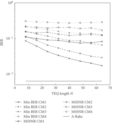
Min BER CM1 Min BER CM2 Min BER CM3 Min BER CM4 MSSNR CM1
MSSNR CM2 MSSNR CM3 MSSNR CM4 A-Rake
Figure 4: The BER performance of different Rake receivers and TEQ designs at SNR =15 dB with a fixed number of interfering users versus increasing TEQ length.
filtering which changes the shape of the transmitted pulse to the second order Gaussian pulse. The modulation index Δ is 2 ns and the chip duration Tc is 5 ns. Other system parameters, for example, , Nu, Nh, and Ns are either kept constant to a certain value or varied in different simulations.
Extensive simulations were performed to test the capa-bilities of the proposed BER minimization TEQ design. The results are generated by averaging the performance parame-ter through Monte Carlo simulations. As an SGA approach is used, all the simulations for BER are performed in low to moderate SNR range. Since the performance depends upon many factors, each factor is considered individually.
Figure 3 shows the BER of the system versus SNR. There were 10 users in the system, including the user of interest. The length of the TEQ was N = 32 and the shortened channel window was = 10 taps long. The performance is evaluated for both the modulation schemes, that is, TH-BPPM and TH-BPSK with Nh = 25 and
Ns = 7. The TH-codes are semiorthogonal for all receivers except the A-Rake. The performance of an ideal A-Rake is used as lower bound with an assumption that the TH-codes of other users are perfectly orthogonal, resulting in zero correlation with the pth user template. It is observed that the performance of the proposed TEQ and other receiver structures is almost the same for both modulation schemes. The proposed TEQ clearly maintains a lower BER in all channel models along with efficiently shortening the channel.
0 0.05 0.1 0.15 0.2 0.25 0.3 0.35
BER
2 4 6 8 10 12 14 16 18 20
Number of interfering users (Nu−1) A-Rake
Min BER MSSNR
Figure 5: The BER performance of different Rake receivers and TEQ designs at SNR = 15 dB andN =32 versus the increasing number of users.
InFigure 4, all other parameters are the same as in the previous figure, except the SNR which is now fixed at 15 dB. The TEQ length is varied from 32 to 64 with an increment of 8. As, the performance of all the receiver structures is found to be the same with TH-BPPM and TH-BPSK, in rest of the results we evaluate the performance only for TH-PPM. Figure 4 is actually a comparison between the MSSNR TEQ and the proposed TEQ as the A-Rake, S-Rake, and P-Rake are not affected by the TEQ length. Only A-Rake’s performance is shown for reference. An increasing value ofNimproves the performance of the proposed TEQ, specially in less dense channels, but, as stated earlier, at the cost of increased receiver complexity. Therefore, the TEQ lengthN can be considered as a designer parameter. If the system is needed to operate at a certain BER in a particular propagation environment,Figure 4can help in choosing the suitable value ofN.
The proposed TEQ performs an optimization in which it tries to keep the MAI at its minimum, while the MSSNR TEQ does not include MAI and hence is incapable of handling a multiuser system. Hence, as shown inSection 4, it enhances the noise and MAI which falls within the shortened channel window. Therefore, as expected, the proposed TEQ is not significantly effected by the increasing number of users as shown inFigure 5. On the other hand, the performance of MSSNR TEQ gradually degrades as the number of users increases. All other system parameters are the same as in the previous case. The performance of A-Rake, S-Rake and P-Rake is found stable because of semiorthogonal TH codes and therefore not shown.
0 0.2 0.4 0.6 0.8 1
Energ
y
captur
e
for
the
p
th
user
(%)
1 6 11 16 21
Length of shortened channel window CM1
(a)
0 0.2 0.4 0.6 0.8 1
Energ
y
captur
e
for
the
p
th
user
(%)
1 6 11 16 21
Length of shortened channel window CM2
(b)
0 0.2 0.4 0.6 0.8
Energ
y
captur
e
for
the
p
th
user
(%)
1 6 11 16 21
Length of shortened channel window CM3
Min BER S-Rake
P-Rake MSSNR (c)
0 0.1 0.2 0.3 0.4 0.5 0.6 0.7
Energ
y
captur
e
for
the
p
th
user
(%)
1 6 11 16 21
Length of shortened channel window CM4
Min BER S-Rake
P-Rake MSSNR (d)
Figure6: The energy capture performance of different Rake receivers and TEQ designs at SNR=15 dB,N =32, andNu=10 versus the
length of shortened channel window.
channel window. The value ofvaries from 2 to 20. This figure is basically a two-dimensional image ofFigure 1and is drawn for all the four channel models. The range of
is selected so that the Rake receiver design is practically simplified and benefits of the TEQ can be seen. As mentioned in Section 6, if the value of is further increased, S-Rake performance will supersede the proposed TEQ. A similar cross-over point can be seen for the MSSNR TEQ. But, larger values ofdirectly contradict the aim of proposing TEQ at the receiver front end and hence are not considered here. Energy capture for A-Rake (not shown) is a straight line parallel to thex-axis and close to unity. The small gap to perfection is due to self-interference.
8. Concluding Remarks
All the major factors which may affect the performance of the proposed TEQ are simulated and discussed. It is shown that the proposed TEQ outperforms the considered MSSNR TEQ and the Rake architectures in any performance aspect. Especially, the proposed TEQ maintains a lower BER while shortening the dense multipath channels to a desired small temporal window. Hence, with the proposed TEQ design, an UWB Rake receiver can be designed with significantly less number of fingers/correlators without compromising the receiver performance in terms of the BER. This will also simplify the receiver architecture and analysis that follow the Rake.
Acknowledgments
The views expressed in this paper are those of the authors, and do not reflect the official policy or position of the United States Air Force, Department of Defense, or the U.S. Government. This document has been approved for public release; distribution unlimited.
References
[1] A. Cantoni and P. Butler, “Properties of the eigenvectors of persymmetric matrices with applications to communication theory,”IEEE Transactions on Communications, vol. 24, no. 8, pp. 804–809, 1976.
[2] D. D. Falconer and F. R. Magee Jr., “Adaptive channel memory truncation for maximum likelihood sequence estimation,”Bell System Technical Journal, vol. 52, no. 9, pp. 1541–1562, 1973. [3] G. D. Forney Jr., “Maximum-likelihood sequence estimation
of digital sequences in the presence of inter symbol interfer-ence,”IEEE Transactions on Information Theory, vol. 18, no. 3, pp. 363–378, 1972.
[4] F. R. Magee Jr., “A comparison of compromise Viterbi algorithm and standard eqaulization techniques over band limited channels,”IEEE Transactions on Communications, vol. 23, no. 3, pp. 361–367, 1975.
[5] N. Al-Dhahir and J. M. Cioffi, “Efficiently computed reduced-parameter input-aided MMSE equalizers for ML detection: a unified approach,”IEEE Transactions on Information Theory, vol. 42, no. 3, pp. 903–915, 1996.
[6] T. Miyajima and Z. Ding, “Second-order statistical approaches to channel shortening in multicarrier systems,”IEEE Transac-tions on Signal Processing, vol. 52, no. 11, pp. 3253–3264, 2004. [7] P. J. W. Melsa, R. C. Younce, and C. E. Rohrs, “Impulse response shortening for DMT transceivers,”IEEE Transactions on Communications, vol. 44, no. 12, pp. 1662–1672, 1996. [8] C. Yin and G. Yue, “Optimal impulse response shortening for
discrete multitone transceivers,”Electronics Letters, vol. 34, no. 1, pp. 35–36, 1998.
[9] J. Balakrishnan, R. K. Martin, and C. R. Johnson Jr., “Blind adaptive channel shortening by sum-squared auto-correlation minimization (SAM),”IEEE Transactions on Signal Processing, vol. 51, no. 12, pp. 3086–3093, 2003.
[10] R. K. Martin, J. Balakrishnan, W. A. Sethares, and C. R. Johnson Jr., “A blind adaptive TEQ for multicarrier systems,”
IEEE Signal Processing Letters, vol. 9, no. 11, pp. 341–343, 2002. [11] I. Medvedev and V. Tarokh, “A channel-shortening multiuser detector for DS-CDMA systems,” in Proceeding of the 53rd
IEEE Vehicular Technology Conference (VTC ’01), vol. 3, pp. 1834–1838, Rhodes, Greece, May 2001.
[12] A. Rajeswaran, V. S. Somayazulu, and J. R. Foerster, “Rake performance for a pulse based UWB system in a realistic UWB indoor channel,” inProceedings of the IEEE International Conference on Communications (ICC ’03), vol. 4, pp. 2879– 2883, Anchorage, Alaska, USA, May 2003.
[13] S. I. Husain and J. Choi, “Single correlator based UWB receiver implementation through channel shortening equalizer,” in
Proceedings of the 11th Asia-Pacific Conference on Communi-cations (APCC ’05), pp. 610–614, Perth, Wash, USA, October 2005.
[14] S. I. Husain and J. Choi, “Blind adaptive channel shortening by unconstrained optimization for simplified UWB receiver design,” inProceedings of the 3rd International Symposium on Wireless Communication Systems (ISWCS ’06), pp. 443–446, Valencia, Spain, September 2006.
[15] S. I. Husain, J. Yuan, and J. Zhang, “Modified channel shortening receiver based on MSSNR algorithm for UWB channels,”Electronics Letters, vol. 43, no. 9, pp. 535–537, 2007. [16] S. I. Husain, J. Yuan, and J. Zhang, “Rake performance after channel shortening by decay factor optimization in UWB channels,” inProceeding of the 66th IEEE Vehicular Technology Conference (VTC ’07), pp. 1204–1207, Baltimore, Md, USA, October 2007.
[17] J. R. Foerster, et al., “Channel modelling sub-committee report final,” Tech. Rep. IEEE P802.15-02/490r1-SG3a, Working Group for Wireless Personal Area Networks, Monterey, Calif, USA, February 2003.
[18] R. K. Martin, G. Ysebaert, and K. Vanbleu, “Bit error rate minimizing channel shortening equalizers for cyclic prefixed systems,”IEEE Transactions on Signal Processing, vol. 55, no. 6, pp. 2605–2616, 2007.
[19] A. A. M. Saleh and R. Valenzuela, “A statistical model for indoor multipath propagation,”IEEE Journal on Selected Areas in Communications, vol. 5, no. 2, pp. 128–137, 1987.
[20] G. H. Golub and C. F. Van Loan,Matrix Computations, The Johns Hopkins University Press, Baltimore, Md, USA, 1996. [21] D. S. Watkins,Fundamentals of Matrix Computations, John
Wiley & Sons, New York, NY, USA, 1991.
[22] S. Gezici, M. Chiang, H. V. Poor, and H. Kobayashi, “Optimal and suboptimal finger selection algorithms for MMSE rake receivers in impulse radio ultra-wideband systems,”EURASIP Journal on Wireless Communications and Networking, vol. 2006, Article ID 84249, 10 pages, 2006.