Article
1
Intelligent communication in Wireless Sensor
2
Network
3
Mostefa Bendjima 1, Mohammed Feham 2
4
1 STIC Laboratory, University of Tlemcen
5
P.O.Box 230, Chetouane, 13000 Tlemcen- Algeria; [email protected]
6
2 STIC Laboratory, University of Tlemcen
7
P.O.Box 230, Chetouane, 13000 Tlemcen- Algeria; [email protected]
8
* Correspondence: [email protected]
9
10
Abstract: Wireless Sensor Networks (WSN) is designed to collect information across a large
11
number of limited battery sensor nodes. Therefore, it is important to minimize the energy
12
consumption of each node, which leads to the extension of the network life. Our goal is to design an
13
intelligent WSN that collects as much information as possible to process it intelligently. To achieve
14
this goal, an agent has been migrated to each node in order to process the information and to
15
cooperate with these neighboring nodes while Mobile Agents (MA) can be used to reduce
16
information between nodes and send those to the base station (Sink).
17
This work proposes to use communication architecture for wireless sensor networks based on the
18
Multi Agent System (MAS) to ensure optimal information collection. The collaboration of these
19
agents generates a simple message that summarizes the important information in order to transmit
20
it by a mobile agent. To reduce the size of the MA, the nodes of the network have been grouped
21
into sector. As for each MA, we have established an optimal itinerary, consuming a minimum
22
amount of energy with the data aggregation efficiency in a minimum time.
23
Successive simulations in large scale wireless sensor networks through the SINALGO simulator
24
show the performance of our proposal, in terms of energy consumption and package delivery rate.
25
Keywords: Wireless sensor network, agent cooperation, mobile agent, itinerary, multi agent
26
system, communication.
27
28
1. Introduction
29
Advances in wireless technologies and technologies in micro manufacturing and microprocessor
30
integration have created a new generation of Wireless Sensor Network (WSN) for a wide range of
31
applications.
32
A wireless sensor network consists of a set of nodes capable of collecting information from a
33
monitored environment and transmitting it to a base station (Sink) via the wireless medium. WSNs
34
are often characterized by dense, large scale deployment in resource constrained environments. The
35
limits imposed are the limitation of processing capacity, storage and especially energy because they
36
are usually powered by batteries. The constraint of the size of a sensor node forces designers to limit
37
the size of its battery and therefore the amount of energy available. Replacing a battery is rarely
38
possible, either for cost reasons or environmental constraints. This causes a problem related to the
39
energy consumption during operation of the various nodes of the network.
40
The WSN have given rise to many research issues in order to improve network performance,
41
including maximizing its lifespan. And as a result, unlike traditional networks that are concerned
42
with ensuring a good quality of service, the WSN must give primary importance to energy
43
conservation. It is therefore widely recognized that energy limitation is a key issue in the design of
44
the WSN because of the strict constraints it imposes on the operation of the network. Experimental
45
measurements have shown that, in general, data transmission is very expensive in terms of energy
46
consumption, while data processing consumes much less [1]. The cost of the transmission energy of
47
an information bit is approximately the same as that required for processing a thousand operations
48
in a typical sensor node [2]. The lifespan of a sensor network can be extended by the application of
49
different techniques of energy consumption. One of these techniques is the technique of partitioning
50
the network into sectors, as in our previous work [3].
51
For the past ten years, Multi Agent Systems (MAS) have grown rapidly and are applied to a wide
52
variety of fields such as, for example, the field of simulation and artificial life, robotics, and images
53
processing. It is integrated in the WSN, because of their intelligence and adaptation to the field. Ant
54
colonies, spiders, etc., are examples of MAS, which are applied to the WSN to process captured data,
55
routing, detection of shorter itinerary, etc.
56
The integration of Mobile Agent (MA) into the WSN solves several problems that can harm the
57
wireless sensor network. Indeed, it can be used to reduce the cost of communication significantly, in
58
particular the elimination of redundancies, by moving the processed data by an agent introduced
59
into each node instead of bringing them to the raw state at Sink by the knot itself.
60
In this work, we will realize a system capable of simulating a network of wireless sensors in an
61
environment, in order to minimize the energy dissipation. The multi agent system principle of
62
operation is used for the intelligent processing of the data captured by the nodes, in terms of
63
reduction of redundancy, evaluation of their importance, elimination of non useful information, and
64
cooperation between the sensor nodes neighbors. The main purpose of this technique is to group the
65
data by a mobile agent and send them at a time to minimize transmission, instead of each node
66
sending data through intermediate nodes. It also incorporates the principle of multi agent system
67
operation for the intelligent processing of the data captured by the nodes, in terms of reduction of
68
redundancy, the evaluation of their importance, and the elimination of non useful information. A
69
mobile agent activated by the Sink has been proposed and sent to the sector. This agent will circulate
70
in the sector nodes in an itinerary schema specified, to gather the processed and captured data by the
71
agents (node).
72
In other words, an agent has been integrated in each sensor node, such that each node of the
73
network is seen as an autonomous agent having its own characteristics and behaviors towards the
74
various events they receive. Mobile agent is used to reduce the cost of communication dramatically,
75
in particular, the elimination of redundancies between source nodes, by moving information
76
processed by an agent introduced into each node instead of bringing them to sink in the raw state. In
77
addition, the source nodes cooperate with these neighbors to ensure the movement of the MA. So,
78
these agents (introduced in the nodes) eliminate the redundant information that contains in the MA
79
and the node by itself. Iteratively, the network was partitioned into sectors [3] where the source
80
nodes in each sector are included in an itinerary. This technique makes it possible to find an optimal
81
itinerary for an MA to collect data from several distributed sensor nodes. The source nodes within
82
each sector can be obtained by choosing the angle in an adaptive itinerary. The main purpose of this
83
instead of each node sending their data. To collect data in each area, we have created an itinerary
85
algorithm, so that it allows the mobile agent to:
86
• Reduce the response time;
87
• Travel the itinerary from the furthest node to the well;
88
• Start aggregating data from the source node as much as possible until you reach Sink;
89
• Consumes less energy on the itinerary back to the sink;
90
• Avoid exhausting energy when visiting source nodes;
91
• Decrease the chances of being lost due to not enough energy from the source nodes;
92
• Use neighboring nodes to help source nodes that have less energy.
93
The rest of the article is organized as follows: section 2 provides an overview of the literature in
94
which algorithms for a number of studies have been performed regarding routing in the WSN, in the
95
first place, the classification of proposed routing solutions, then the solutions proposed in the
96
integration of mobile agents in the directed diffusion protocol, and we present the statement of the
97
problem. In section 3, we present the description of our communication strategy. Mobile agent
98
packet structure for itinerary planning and the data collection cooperation are described in Sections
99
4 and 5, respectively. Next, section 6 sets out the purpose of our application, which is to establish a
100
system to simulate the communication between a set of sensors and a base station. Then, Section 7
101
shows the evaluation of our proposal through simulation, while Section 8 analyzes the results of our
102
approaches compared to other approaches, according to several criteria. Finally, Section 9
103
summarizes and concludes this article.
104
2. Related Work
105
In wireless sensor networks, the main issue concerns energy consumption. Indeed, since it is not
106
possible to recharge the energy of the sensor nodes, they must remain operational as long as
107
possible, so it is necessary to save the maximum energy consumed by these nodes. One of the
108
characteristics of sensor networks is the ability to reduce the amount of data flowing through the
109
network, in order to conserve energy, by merging data through particular nodes in the network. This
110
process is called data aggregation. Aggregation not only requires the transmission of data but also
111
imposes constraints on the architecture of the network. The basic idea of this architecture is to
112
combine data from different source nodes by eliminating existing redundancies and also minimizing
113
the number of transmissions possible to save the amount of energy consumed. In what follows we
114
present some work in this subject.
115
The most energy efficient proposals are based on the traditional Client/Server (C/S) model, to
116
manage multi-sensor data fusion in the WSN. Several works [4-11] have been realized to optimize
117
the architecture of this model. In this architecture, when a sensor node detects information from the
118
environment, it sends it as raw data through the other nodes to sink for processing. The transmission
119
of raw information does not eliminate unnecessary or redundant information, which requires costly
120
construction in terms of energy.
121
A number of research papers have proposed Compression/Decompression (C/D) of data
122
algorithms to reduce the ability of information transmitted by sensors. The authors of [5,6] proposed
123
a data correlation algorithm that compresses the data in a WSN. In this proposal, only one node is
124
elected to send raw data to sink and the others only sent encoded data. After having the Sink
125
received the data, he decodes it through the correlations between the compressed and
126
uncompressed data. However, it is quite difficult to find a non-complex coding algorithm
127
In [7], the authors proposed a Data Fusion (DF) of a maximum number of sensors. When a node
129
sends its data to Sink, the intermediate nodes merge their data with the ones of the first node. So, this
130
information is merged into one message instead of many, which saves energy. However, the
131
intermediate nodes do not always have important information to send, nor do they eliminate the
132
unimportant or redundant information. In addition, the authors neglected to study the importance
133
of the scalability of this type of networks.
134
Additionally, researchers [9] have proved that cluster is a fundamental technique in the WSN.
135
Their goal is to minimize the processing of aggregation of the data needed at the sensor node and
136
move the load to the Sink. The clustering algorithm uses a hierarchical classification, and the nodes
137
organize into groups and elect a cluster node as a leader. The latter collects the aggregated
138
information from the sensors of his group and transmits them to the Sink. In this itinerary, a
139
significant reduction in energy consumption is realized. Unfortunately, the authors did not address
140
the problem of the complexity and amount of energy consumption required to build such clustered
141
sensor networks.
142
In addition to [8,9], the authors of [12-15] also proposed a structured strategy (Tree and Cluster)
143
based on data aggregation for the WSN. However, according to [16,17], structured approaches are
144
not practical for dynamic scenarios, due to excessive communication costs and the centralization of
145
the management of the structure WSN.
146
The authors of [8] proposed an ant colony algorithm for data aggregation in the WSN. Each ant
147
will explore all possible itineraries from the source node to Sink. The data aggregation tree is
148
constructed by the accumulated pheromone. But, the construction of this appropriate tree depends
149
largely on the deployment of nodes, which is usually random which consumes a significant amount
150
of energy. However, the Euclidean distance calculated from a Sink source node may not be
151
applicable in the WSN because the communication range of a node is limited.
152
A Multi Agent System is a group of agents able to interact and cooperate to achieve a specific
153
goal. Different properties are defined as autonomy, proactivity, flexibility, adaptability, ability to
154
collaborate and coordinate tasks, etc.
155
The researchers proposed to use multi agent system solutions on the adaptation of distributed
156
and complex wireless sensor networks. The researchers [18-24] have realized the community of
157
artificial intelligence with intelligent sensors by the use of this system. Intelligent sensor node
158
operates as stand-alone agents that develop a network of intelligent sensors. In our previous work
159
[3,18,24], we proposed an approach of a communication using MAS in a WSN plan. So, with this
160
solution we solved the density problem, by partitioning the network into clusters. We have yet,
161
extend this work into another work [25], a scheme has been proposed to aggregate a maximum of
162
information. In this work, we integrated in each sensor node an agent, in order to process the
163
information and each node can cooperate with its neighbors.
164
The authors of [4,10,11,13-15] proposed mobile agent technology in the WSN for data collection.
165
In these proposals, the MA is defined as a message that contains an application code, a list of source
166
nodes predefined by the Sink, and an empty field to put the collected data. It is able to move
167
between all the source nodes of the network by moving the captured data in a single message
168
instead of each node itself bringing this raw information to Sink. The use of MAs allows for more
169
efficient data aggregation over C/S. In these proposals, the MA visits the source nodes of the
170
type of solution is the difficulty of creating the list of source nodes and defining the start time of the
172
data collection. Another limitation is the definition of the regions to be treated by the MA. But, as a
173
solution to optimize the MA itinerary in data fusion, the authors [16] proposed two heuristic
174
itinerary algorithms. The Local Closest First (LCF) algorithm, the mobile agent starts its itinerary
175
from one node and searches for the next destination with the shortest distance to its location. The
176
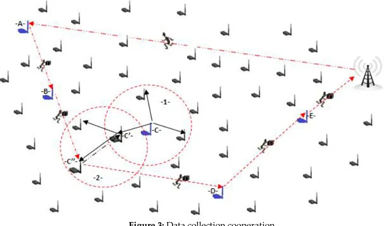
Global Closest First (GCF) algorithm, the mobile agent starts their itinerary from a node and selects
177
the next destination with the closest to the center of the surveillance zone.
178
Due to the limited bandwidth and the density of wireless sensor network, the use of a single
179
mobile agent, can lead to a very inefficient design. In addition, the use of a single MA that
180
successively visits all the source nodes of a large scale network may have the following drawbacks:
181
• Can actually lead to a very long response time, with many of the source nodes to visit;
182
• The sensor nodes in the MA itinerary exhaust the energy quickly than other nodes;
183
• During the visit of the source nodes, the size of MA increases continuously;
184
• MA transmission will consume more energy in its return itinerary to the sink;
185
• The increasing amount of data accumulated by the MA during his migration task increases his
186
chances of being lost due to the noise in the wireless medium.
187
Authors [17,18] have proposed the use of multiple mobile agents for data fusion, which also
188
involves extending network lifetime. On the other hand, when mobile agents are used for data
189
merging tasks, the choice of moving itinerary for MAs is essential. While it is crucial to find an
190
optimal itinerary for each mobile agent to visit al the indicated source node.
191
Chen et al. [19] proposed the Location based Multi agents Itinerary Planning (CL-MIP) algorithm;
192
the main idea is to consider the Multi agent Itinerary Planning (MIP) solution as an iterative version
193
of the solution Single agent Itinerary Planning (SIP). Another algorithm, Genetic Algorithm based
194
Multi agents Itinerary Planning (GA-MIP) is proposed in [20]. GA-MIP first proposes a new two
195
level MA coding method to solve the MIP problem. The GA-MIP algorithm considers the MIP
196
problem as a single problem instead of using several steps adopted by the previous algorithms. The
197
proposal in [21] considers models of MIP problems as a Totally Connected Graph (TCG). In the TCG,
198
the vertices are the sensor node of the network, and the weight of an edge is derived from the
199
estimates of the jump between the two edge nodes of the edge. The authors indicate that all source
200
nodes in a particular sub-tree should be considered as a group. In addition, they have a balancing
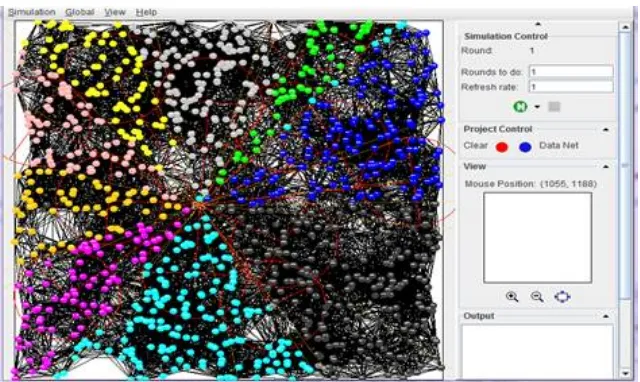
201
factor, while calculating the weights in the TCG, to form a minimum Balanced Spanning Tree (BST).
202
Mpitziopoulos et al. [22] proposed the Near-Optimal Itinerary Design (NOID) algorithm to solve
203
the problem of calculating a near-optimal itinerary for an MA. The NOID algorithm was designed
204
on the basis of rapidly adapting to network change conditions, the MA itinerary should only include
205
source nodes with sufficient energy availability, and the number of AMs should depend on number
206
and physical location of source nodes to visit.
207
Gavalas et al. [23] presented the Second Near-Optimal Itinerary Design algorithm (SNOID) to
208
determine the number of MAs that should be used and the itinerary of these MAs should follow. The
209
main idea behind SNOID is to partition the area around the Sink into concentric areas and start
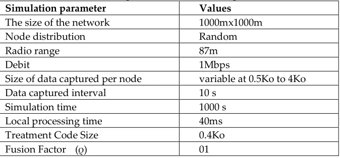
210
building the MA roads with the direction of the interior near Sink. All source nodes within the first
211
zone are connected directly to the Sink, and these nodes are the starting points of the MA itinerary.
212
After having analyzed the solutions presented above, we can also deduce that there is still a lot of
213
work in terms of energy efficiency by paying attention to the report of delivery of packets and the
214
3. The communication strategy
216
Our strategy ensures better data collection management in a WSN, taking into consideration the
217
energy of each sensor node to improve network performance. Due to the fact that a lot of the
218
detected information could be redundant or not important, an optimization for the data collection
219
could be a good technique to save the energy of the sensor node and extend the network lifetime.
220
In this work, we propose an intelligent strategy that collects information and processes
221
intelligently. According to [1] to send a quantity of information in a single message is less than
222
sending the same amount in several short messages. So, because of the density of the network, and
223
the highest energy consumption at the communication level, instead of each node sending its data to
224
Sink, the network has been broken down into sector.
225
Our strategy is as follows: An agent is introduced in each node of the network, which processes
226
the information at the local level and judges their importance in order to eliminate any unnecessary
227
or redundant information and to make the cooperation between neighboring nodes. In addition, the
228
source nodes cooperate with their neighbors in order to transmit information.
229
First, we grouped the sensor nodes into sectors, in addition, we proposed a mobile agent at the
230
level of each sector, in order to concatenate the information processed by the source nodes, to send
231
them in a single message by a well defined strategy.
232
After the Sink designates the source nodes, it sends each sector an MA, to aggregate the data,
233
with a list of well defined source nodes. The list of source nodes is sorted according to an itinerary
234
algorithm, so that the MA circulates between these nodes. For a neighboring node to cooperate with
235
its source node, it must be based on two possible behaviors. The first behavior is that a node
236
cooperates with other nodes of the network, as much as possible in order to save the transmission of
237
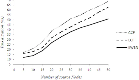
information. Indeed, the reduction of cooperation can lead to the loss of certain appropriate
238
information. The node consumes some energy in its cooperation, but it reduces the probability of
239
losing important information. The second behavior is that a node agrees to cooperate with the
240
network nodes that are in the itinerary to the Sink. Indeed, the node consumes some energy in its
241
cooperation, but it guarantees the transmission of the packets. During the itinerary of a mobile agent,
242
if the energy of the next source node is not sufficient enough to transmit the mobile agent, this sensor
243
node transmits this information to an intermediate node between itself and the next source node of
244
the list.
245
Our sector approach based on multi agent system is divided into three phases: the first phase is to
246
determine the source nodes satisfying the interest according to the direct diffusion, the second phase
247
is to plan the network into sectors, and the third phase is to determine the itinerary of the mobile
248
agent in each sector to collect the data.
249
3.1. Detecting source nodes
250
Once, the Sink receives a new task requested by an application, first, Sink broadcasts interest
251
packets to detect the source nodes that perform the task, according to the Direct diffusion routing
252
protocol. So, it generates a message (interest), and then sends it to all its neighboring nodes in a
253
single hop. These neighbors send this message to their neighbors and so on. The purpose of
254
spreading this message is to discover all the source nodes that perform the task, and also it will allow
255
us to know and identify all the nodes of our sensor network.
256
3.2. Partition the network into sector
257
As in our previous work [25], once, the Sink receives the identifiers of the source nodes, after a
258
definite delay, the Sink partitions the network in sectors, with the starting point is the base station, as
259
261
Figure 1: partitioning the network into sectors
262
3.3. Plan the MA itinerary
263
At this stage, mobile agents activated by the Sink have been proposed. The latter will send these
264
agents, so that they circulate between the nodes of its sectors. These mobile agents aggregates data
265
processed and captured by the source nodes to return to Sink with the collected information. To plot
266
the MA itinerary, we have created an algorithm, which allows finding an optimal itinerary, in order
267
to manipulate the list of nodes in a coherent itinerary.
268
Our algorithm allows a mobile agent to move from a source node further to a source node closer
269
to Sink, to avoid overloading the MA. The latter determines the list of source nodes they will be
270
visited according to the distance between the source node and Sink. So that the first source node of
271
the list is the one furthest from the sector and the same for the other source nodes.
272
4. Mobile Agent
273
4.1. Mobile Agent Packet Structure
274
After Sink uses direct diffusion to designate the source nodes, it sends each sector a mobile agent.
275
The latter is a packet of data circulating in the sector, it is used to collect the data captured by the
276
source nodes. The information contained in a mobile agent packet is shown in figure 2.
277
Sec_ID MA_Seq_N Next_Src_ID Src_List Int_List Data_Cooperation
Figure 2: MA Packet Structure.
278
Both attributes are used to identify a mobile agent packet(sec_ID and MA_Seq_N). Whenever
279
Sink sends a new MA packet, it increments the MA_Seq_N. The Src_List list specifies the source
280
nodes of the sector, which will be visited by the mobile agent. This list will be filled in by Sink.
281
Next_Src_ID specifically determines the succession of source node identifiers that must be visited by
282
the MA. If Next_Src_ID is equal to Sink, it means that it is the last node visited by the mobile agent.
283
The Int_List list specifies the intermediate nodes (the help nodes) between the source nodes.
284
Data_Cooperation contains the information that is processed by the source nodes of the itinerary
285
(useful and non-redundant information). It is from the 2nd source node of the itinerary that the MA
286
begins to process the redundancy of information collected at the node and so on.
287
4.2. MA itinerary planning
288
To plot the mobile agent itinerary, we have created an algorithm, which makes it possible to find
289
an optimal and efficient itinerary, in order to manipulate the list of source nodes in a coherent
290
itinerary. Our algorithm allows a mobile agent to move from a sensor node further to a sensor node
291
closer to Sink. So, the itinerary starts at the first sensor node with the longest distance, and ends with
292
In order for the mobile agent to avoid collecting redundant information between the source
294
nodes, we calculate the size of the detected data accumulated by this MA using the method used by
295
[21]. According to this method, a captured data sequence can be combined with a merge factor ρ. Let
296
Ni be the amount of accumulated data accumulated after the MA collects the Ni (Source Node i)
297
result, and Ri the size of the locally processed sensed data that will be accumulated by the MA at the
298
Ni. So we have: N1 = R1 ; Ni = N1 + ∑ ρ . Rk (i >=2)
299
Algorithm 01: Chaining source nodes at the Sink level
300
Begin
301
If Sink receives source nodes identifications by DD then
302
Begin
303
// The Sink fills Src_List;
304
max = L[1] ; // L: list contains the source nodes after applying the DD protocol
305
For i = 2 to N Do
306
If d(Sink , max) < d(Sink , L[i]) Then // the farthest distance with the Sink
307
max = L[i]
308
EndFor;
309
MA@ Src_List[1]:= max ; // max: the farthest distance with the Sink
310
MA@ Src _First = max;
311
L = L – {max};
312
For i =1 to N Do
313
min = L[i];
314
For j=2 To N Do
315
If d(MA@Src_List[i] , min) > d(MA@Src_List[i] , L[j]) Then
316
min=L[j]
317
EndFor
318
MA@ Src_List[i+1]= min ;
319
L = L – {min};
320
N=N-1
321
EndFor
322
End ;
323
End.
324
Algorithm 02: Pass the MA between the source nodes;
325
Begin
326
While MA arrives at a nodei but not Sink do
327
If Nodei has new data then
328
If MA is empty then
329
N=R1 ; // Put the data to the MA package
330
Next_Src_ID = read the new destination from Src_List;
331
Pass the MA to Next_Src;
332
Else
333
If Nodei data already exists in the MA Packet then
334
// Ignorer les données et passer au suivant ;
335
Next_Src_ID = read the new destination from Src_List;
336
Pass the MA to Next_Src;
337
Else
338
N=N+ ∑ ρ . Ri ; // Put the data to the MA package
339
Else
340
Next_Src_ID = read the new destination from Src_List;
341
Pass the MA to Next_Src;
342
5. Data Collection Cooperation
344
Figure 03 illustrates the cooperation of source nodes that do not have enough energy (to transmit
345
the MA) with their neighbors during the data collection sessions. The source node C, which does not
346
have enough energy, begins to seek cooperation near its neighbors of the itinerary when the
347
previous source node B receives an MA as shown in step (1). The cooperation request is a short
348
message, programmed for a single hop, and neighbors will be programmed not to replay this
349
message. Thus, the node C waits during a fixed delay, if no neighboring node does have not enough
350
energy; the sensor node considers that these neighboring nodes are not cooperating nodes. In this
351
case, the message is programmed for two hops and so on until a cooperating node is obtained
352
(source node or a simple neighbor node knowing that the priority of choice goes to the source node).
353
So, the source node makes the decision to cooperate or not with a neighbor according to a specific
354
energy threshold and which is in the itinerary of the list. After the appropriate decision is made, the
355
source node C sends its processed information (useful and non-redundant) to the cooperating
356
neighbor node C ''. Then, the previous source node B sends the MA to the cooperating neighbor
357
node C '', as shown in step (2).
358
The other following source nodes in Src_List list of MA repeat the same previous steps until they
359
reach Sink.
360
361
Figure 3: Data collection cooperation
362
Algorithm 03: pass the MA between the source nodes
363
Begin
364
Pass the MA to MA@First_Src ;
365
While MA arrives at source node Do
366
If MA@Next_Src_ID does not have enough energy Then
367
For i = 1 to node@Nbr_ neighbor Do // neighboring number of source nodes
368
Node diffuse ReqCoop
369
EndFor
370
If deadlines <= D and neighbor node cooperating responds Then
371
// the waiting time to send the MA to the next
372
If node receives ReqCoop Then
373
If E > S Then // if the energy remaining> at a predefined threshold
374
neighbor node cooperating responds
375
EndIf
376
EndIf
377
Else
379
For i = 1 to node@Nbr_ neighbor Do // neighboring number of nodes neighbor
380
Node diffuse ReqCoop
381
If neighbor node = source node
382
N=N+ ∑ ρ . Ri
383
EndIf
384
EndFor
385
EndIf
386
EndIf
387
Fill in the MA@Int_List // by the intermediate nodes between the two source nodes
388
MA@Next_Node = read the new destination from MA@Int_List ;
389
Pass the MA at MA@Next_Node ;
390
End.
391
The energy E represents only the remaining battery level, plus E of a node has more, it is
392
advisable to participate in the cooperation.
393
6. Simulation setup
394
For our simulation platform, we chose to use the Sinalgo simulator: it is a simulator that allows
395
creating, simulating and validating distributed algorithms [24]. We have established a system to
396
simulate a communication between a set of sensors and a Sink form a WSN. It is based on the
397
technique of partitioning the network into sectors and the use of multi agent system and mobile
398
agents, which are considered as a mechanism to save the energy of a WSN. So, we will achieve an
399
effective application in terms of energy consumption, the task duration and the packet drop ratio. In
400
order to design our simulator, we have adopted the following assumptions:
401
The sensor nodes have limited energy;
402
Sink has an infinite supply of energy;
403
Sink and sensor nodes are stationary;
404
At the beginning, each sensor has an initial energy;
405
After network activation, each node is an agent;
406
The administrator chooses the number of nodes, the radius and the position of Sink;
407
The number of sensors is limited;
408
Node positions are known;
409
The deployment is random;
410
Two sensors do not occupy the same coordinates.
411
We performed our simulations on a 1000m x 1000m square with a random distribution of nodes
412
for 1000 seconds. We limited the radio range and data rate of each node to 87 meters and 1Mbps,
413
respectively, as suggested in [12]. Transmit and receive power parameters, which directly influence
414
the radio range, have been chosen from the ranges defined in the sunspot system [17]. The local
415
processing time is set at 40 ms. Table1 represents the simulation parameters:
416
Simulation parameter Values
The size of the network 1000mx1000m
Node distribution Random
Radio range 87m
Debit 1Mbps
Size of data captured per node variable at 0.5Ko to 4Ko
Data captured interval 10 s
Simulation time 1000 s
Local processing time 40ms
Treatment Code Size 0.4Ko
Fusion Factor (ρ) 01
7. Evaluation of the proposal
418
Mobile agents and multi agent systems have been proposed to significantly reduce
419
communication costs, which have a significant impact on the efficacy of the WSN. Several works
420
have been done, as explained in section 2, prove that the use of multi agent systems in the WSN is
421
more efficient. As in our previous work, we have demonstrated that the integration of stationary
422
agents in sensors is more efficient, as well as the partitioning of a network into sectors by providing a
423
Client/Server network or a clustered network. Still, several works have been done, prove that the use
424
of mobile agents in the WSN is more efficient. Among these works in Section 2, Local Closest First
425
(LCF) and Global Closest First (GCF) are simple approaches to itinerary planning for a single mobile
426
agent. LCF looks for the next source node that has the shortest distance from the current node, while
427
GCF looks for the next source node, which has the shortest distance from the base station.
428
Our article proposes to use an intelligent strategy based on multi agent systems and mobile
429
agents for the aggregation of data in a WSN and processed them intelligently. The proposed strategy
430
is called: Intelligent Itinerary based on a Wireless Sensor Network (IIWSN).
431
8. Results and analysis
432
So, in order to demonstrate the performance of our approach IIWSN in the WSN, we compare it
433
to the LCF and GCF approaches, according to two criteria. First, we examine the impact of the
434
number of source nodes on the criterion of energy performance, this parameter is considered the
435
most important criterion. Since energy consumption is the parameter that defines the life of the
436
WSN, we set the number of source nodes from 05 to 60 in steps of 05, and obtain a set of results for
437
each case. We have shown the results thus obtained in figure 04, which show the impact of the
438
number of source nodes on the energy, to obtain sensory data of all the source nodes.
439
440
Figure 04 : Comparison of Energy Consumption
441
Figure 04 shows the comparison of the performances of the three approaches in terms of energy.
442
First, and quite normal, when the number of source nodes is increased, more energy is needed to
443
perform the tasks of each of the three approaches. We note that our IIWSN approach is always better
444
than the GCF approach regardless of the number of source nodes, and better than the LCF approach
445
from where we increased the number of source nodes. We can conclude that the difference between
446
our approach and the other two approaches is becoming more and more important, and this
447
difference increases continuously with the increase in the number of source nodes.
448
At first, there is not a difference between IIWSN and LCF, but there is a small difference between
449
our and GCF. From 20 source nodes, our approach minimizes energy consumption by more than 3%
450
at LCF and 12% at GCF. However, at 60 source nodes, the consumption of our approach minimizes
451
energy consumption by more than 29.5% and 42% than LCF and GCF respectively. By comparison of
452
Moreover, and in another experiment, we show the comparison of the performances of the three
454
approaches in criterion of duration of a task. For LCF and GCF approaches, the task duration is
455
equivalent to the average end-to-end reporting delay, from the time when MA is dispatched by the
456
sink to the time when the agent returns to the sink. However, the duration includes the processing
457
time of the data at the source nodes to eliminate redundancies. So, since several mobile agents are
458
working in parallel, and with several experiments, we calculated the duration of a task of a mobile
459
agent to return to the Sink, So, the duration of a task is the average time of an agent mobile where his
460
itinirairy starts from Sink until he returns to him. However, the duration includes the information
461
processing time at the nodes, plus the co-operating time of the source nodes that do not have enough
462
energy to transmit the MA with its neighbor nodes, and the longer the time of the mobile agent. The
463
results obtained are shown in FIG.5.
464
465
Figure 05 : Comparison of task duration
466
The figure above shows the comparison of the performance of the three approaches in terms of
467
task duration. First of all, and quite normal, when the number of source nodes is increased, plus the
468
time required for mobile agents to perform the tasks of each of the three approaches. By observing
469
the results, we can see with more source nodes to visit, the size of an MA becomes more and more
470
and many transmissions will be made. At first, almost both LCF and GCF approaches are similar,
471
but from 10 source nodes, GCF consumes more time than LCF. Compared to energy performance,
472
regardless of the number of source nodes, we note that our approach in terms of task duration is
473
always lower than the LCF and GCF approaches. It may be further remarked that the difference
474
between our proposition and the other two approaches becomes more and more important, and this
475
difference increases continuously with the increase of the number of source nodes. In addition, we
476
notice that maximum value between different values, is less than 10 ms. This means that accuracy
477
could be influenced for applications that are very time sensitive and require less than 10ms. In
478
addition, these differences could be easily explained because with more source nodes to visit, many
479
of the itinerary checks will be done to move the mobile agents.
480
In addition, and in another experiment, we have changed the size of the data captured at each
481
483
Figure 06 : Consommation d’énergie en fonction de size
484
The analysis in the previous figure highlights several interesting elements: first of all, and quite
485
normal, the energy consumption increases with the increase of the size of the packets to perform the
486
tasks of each of the three approaches. The first observation is that the energy consumption of our
487
approach, is also always lower than that of the other approaches and this whatever the size of the
488
packets. On the other hand, when packet size is a bit, the energy consumption of our approach is less
489
important compared to other approaches. The other side, for medium size packets 2Ko, our
490
approach is lower compared to the other approaches of 15% and 22% than that of LCF, and GCF
491
respectively. We can still notice, from 2Ko the difference between our and the other two approaches
492
becomes more and more important, and this difference increases continuously with the increase in
493
the size of the packets. However, for large packets, our approach is advantageous, at 4Ko, IIWSN
494
minimizes energy consumption, more than 23% and 29% to that of LCF, and GCF respectively. By
495
comparison, the solution of our approach presents better energy efficiency.
496
9. Conclusion
497
In an environment where the sensor nodes are close to each other, and where there is
498
considerable redundancy in the sensed data, the sensor nodes generate a large amount of
499
transmissions over the wireless canal, causing not only a loss of the band wireless pass through but
500
also the drawing of a lot of battery energy. Instead of traditional mode approaches like C/S and DF,
501
where the sensor nodes send the raw detected data to Sink, we based ours on a paradigm of MAs
502
and agents at each node to process the information (useful and non redundant information).
503
In this work, we have proposed a strategy that cleverly collects information and processes. As we
504
demonstrated in our previous work, to send a quantity of information in a single message is less
505
than sending them in several short messages. Thus, due to the highest network density and energy
506
consumption at the communication level, instead of each node sending its data to Sink, the network
507
has been broken down into a sector..
508
Our system consists of two types of agents, including stationary agents and mobile agents.
509
Stationary agents consist of integrating an agent into each sensor node, so each agent processes
510
locally sensed information from its corresponding sensor node and estimates its importance. The
511
sensor nodes have been grouped into sectors, and an MA has been proposed at each sector to
512
concatenate the information processed by the source nodes, to send them in a single message by a
513
well defined strategy. This agent will circulate in the sector nodes in a specified itinerary, to collect
514
the processed and captured data by the agents (node). Next, each source node cooperates with its
515
neighboring nodes of the same sector to transmit the mobile agent according to a method based on
516
several important parameters to decide the relevance of cooperation.
517
Our approach limits the communication of non useful information, and consequently decreases
518
the amount of traffic and energy consumed. This means a gain in the amount of information and the
519
that the division of a sector WSN presents better performances comparing to the approaches like C/S
521
and DF, where we used the strategy of the agent.
522
In this work, we have proven through successive simulations that our approach shows better
523
performance compared to LCF and GCF approaches, in terms of power consumption and packet
524
delivery rate in the dense wireless sensor network. The reason for these results is that in our
525
approach the MA guaranteed the collection of information in his itinerary. Because source nodes
526
that do not have enough energy to cooperate with their neighbors to transmit the mobile agent in a
527
more efficient and safer itineray. As future work, we try to minimize the loss of packets, either by
528
partitioning the network in another way, or we add other parameters to the cooperation formula of
529
the mobile agent with the sensor nodes.
530
References
531
1. Gregory J. Pottie andW. J. Kaiser, (2000) Wireless integrated network sensors. Communications of the ACM,
532
43(5) :5158.
533
2. Sardouk, A., M.Boulahia, L., Gaïti, (2008), Agent-Cooperation Based Communication Architecture for
534
Wireless Sensor Network. In: IFIP/IEEE Wireless Days/Adhoc and Wireless Sensor Networks, UAE, IFIP.
535
3. Optimal itinerary planning for mobile multiple agents in WSN (IJACSA) International Journal of Advanced
536
Computer Science and Applications, Vol. 3, No. 11, 2012.
537
4. Chen, M., Kwon, T., Yuan, Y., Leung, V.C.M, (2006), Mobile Agent Based Wireless Sensor Networks, pp
538
14–21.
539
5. Chou, J., Petrovic, D., Ramchandran, K, (2002), Tracking and exploiting correlations in dense sensor
540
networks. Conference Record of the Thirty-Sixth A silomar Conference on Signals, Systems and Computers,
541
pp 39–43
542
6. Chou, J., Petrovic, D.,Ramchandran, K, (2003), A distributed and adaptive signal processing approach to
543
reducing energy consumption in sensor networks. Joint Conference of the IEEE Computer and
544
Communications Societies. 1054–1062.
545
7. Das, S.R., N.A.P.S, (2004), Serial Data Fusion Using Space-filling Curves in Wireless Sensor Networks. In
546
IEEE, ed.: First Annual IEEE Communications Society Conference on Sensor and Ad Hoc Communications
547
and Networks.182–190.
548
8. Liao, W.H., Kao, Y., Fan, C.M, (2008), Data aggregation in wireless sensor networks using ant colony
549
algorithm. J. Netw. Comput. Appl. 31(4) 387–401. JFIAD-SMA -Journée Francophones IAD et SMA ,
550
Pont-à-Mousson, France.
551
9. Chen, H., Mineno, H., Mizuno, T, (2008), Adaptive data aggregation scheme in clustered wireless sensor
552
networks. Comput. Commun. 31(15) 3579–3585.
553
10.Tong Lang, Qing Zhao, and Srihari Adireddy, (2003), Sensor networks with mobile agents.
554
Multidisciplinary University Reseanh Initiative (MURI) under the Omce of Naval Research ConuaCt
555
NMX)I4-W-I- 0564. and Army Rerearch Laboratory CTA on Communication and Network underGrant
556
DAADlP-OI-2-CQII.
557
11.Wang, Qi, H., Xu, Y., W, (2003), Mobile-agent-based collaborative signal and information processing in
558
sensor networks. Proceedings of the IEEE 91(8).
559
12.Sohraby, K., Minoli, D., Znati, (2007), Wireless Sensor Networks, Technology, Protocols, and Applications.
560
WILLEY.
561
13.Hairong Qi, Yingyue Xu, Xiaoling Wang, “Mobile-Agent-Based Collaborative Signal and Information
562
Processing in Sensor Networks,” in Proceeding of the IEEE, Vol. 91, NO. 8, pp.1172-1183,Aug. 2003.
563
14.Wu, Q., Rao, N.S.V., Barhen, J., etc, “On computing mobile agent itinerarys for data fusion in distributed
564
sensor networks,” IEEE Transactions on Knowledge and Data Engineering, Vol.16, NO. 6 , pp. 740-753,
565
June 2004.
566
15.G. Vigna, Mobile Agents: Ten Reasons For Failure Proceedings of MDM 2004 298-299 Berkeley, CA
567
January 2004.
568
16.Hairong Qi, Feiyi Wang (2001), Optimal Itinerary Analysis for Mobile Agents in Ad Hoc Wireless Sensor
569
Networks, University of Tennessee, Knoxville, Advanced Networking Group MCNC, Research Triangle
570
Park.
571
17.SunTM, (2008), Small Programmable Object Technology (SunSPOT) Theory of Operation. Technical report,
572
Sun Microsystem, SunLabs.
573
Intelligent Wireless Sensor Network Management Based on a Multi-Agent System
574
19.Chen, M., Gonzlez, S., Zhang, Y., Leung, V.C.: ‘Multi-agent itinerary planning for sensor networks’. Proc.
576
IEEE 2009 Int. Conf. Heterogeneous Networking for Quality, Reliability, Security and Robustness (QShine
577
2009), Las Palmas de Gran Canaria, Spain,2009
578
20.Cai,W., Chen, M., Hara, T., Shu, L.: ‘GA-MIP: genetic algorithm based multiple mobile agents itinerary
579
planning in wireless sensor network’. Proc. Fifth Int. Wireless Internet Conf. (WICON), Singapore, 2010.
580
21.Chen, M., Cai, W., Gonzalez, S., Leung, V.C.: ‘Balanced itinerary planning for multiple mobile agents in
581
wireless sensor networks’.Proc. Second Int. Conf. Ad Hoc Networks (ADHOCNETS2010), Victoria, BC,
582
Canada, 2010.
583
22.Mpitziopoulos, A., Gavalas, D., Konstantopoulos, C., Pantziou, G.:Deriving efficient mobile agent itinerarys
584
in wireless sensor networks with NOID algorithm. In Proceedings of the IEEE International Symposium on
585
Personal, Indoor and Mobile Radio Communications (PIMRC’2007), Athens, Greece, pp. 1–5, Sep. 2007.
586
23.Gavalas, D., Pantziou, G., Konstantopoulos, C., Mamalis, B.: New Techniques for Incre- mental Data Fusion
587
in Distributed Sensor Networks. In Proceedings of the 11th Panhellenic Conference on Informatics
588
(PCI’2007), pp. 599–608, (2007).
589
24.Multi Mobile Agent Itinerary for Wireless Sensor Networks International Journal of Emerging Trends &
590
Technology in Computer Science (IJETTCS) Web Site: www.ijettcs.org Email: [email protected],
591
[email protected] Volume 1, Issue 1, May-June 2012.
592
1. Bendjima M., Feham M. (2015) Architecture of an MAS-Based Intelligent Communication in a WSN