University of Windsor University of Windsor
Scholarship at UWindsor
Scholarship at UWindsor
Electronic Theses and Dissertations Theses, Dissertations, and Major Papers
1-21-2016
MULTI SENSOR DATA FUSION FOR AUTONOMOUS VEHICLES
MULTI SENSOR DATA FUSION FOR AUTONOMOUS VEHICLES
Shashibushan YenkanchiUniversity of Windsor
Follow this and additional works at: https://scholar.uwindsor.ca/etd
Recommended Citation Recommended Citation
Yenkanchi, Shashibushan, "MULTI SENSOR DATA FUSION FOR AUTONOMOUS VEHICLES" (2016). Electronic Theses and Dissertations. 5680.
https://scholar.uwindsor.ca/etd/5680
This online database contains the full-text of PhD dissertations and Masters’ theses of University of Windsor students from 1954 forward. These documents are made available for personal study and research purposes only, in accordance with the Canadian Copyright Act and the Creative Commons license—CC BY-NC-ND (Attribution, Non-Commercial, No Derivative Works). Under this license, works must always be attributed to the copyright holder (original author), cannot be used for any commercial purposes, and may not be altered. Any other use would require the permission of the copyright holder. Students may inquire about withdrawing their dissertation and/or thesis from this database. For additional inquiries, please contact the repository administrator via email
MULTI SENSOR DATA FUSION FOR
AUTONOMOUS VEHICLES
By
SHASHIBUSHAN YENKANCHI
A Thesis
Submitted to the Faculty of Graduate Studies
Through the Department of Electrical &
Computer Engineering
In Partial Fulfillment of the Requirements for
the Degree of Master of Applied Science at
the University of Windsor
Windsor, Ontario, Canada
2016
Multisensor data fusion for Autonomous Vehicles
by
Shashibushan Yenkanchi
APPROVED BY:
______________________________________________ Dr. Xiaobu Yuan, External Reader
School of Computer Science
______________________________________________ Dr. Narayan kar, Internal Reader
Department of Electrical & Computer Engineering
______________________________________________ Dr. Jonathan Wu, Advisor
Department of Electrical & Computer Engineering
iii
DECLARATION OF ORIGINALITY
I hereby certify that I am the sole author of this thesis and that no part of this
thesis has been published or submitted for publication.
I certify that, to the best of my knowledge, my thesis does not infringe upon
anyone’s copyright nor violate any proprietary rights and that any ideas, techniques,
quotations, or any other material from the work of other people included in my thesis,
published or otherwise, are fully acknowledged in accordance with the standard
referencing practices. Furthermore, to the extent that I have included copyrighted
material that surpasses the bounds of fair dealing within the meaning of the Canada
Copyright Act, I certify that I have obtained a written permission from the copyright
owner(s) to include such material(s) in my thesis and have included copies of such
copyright clearances to my appendix.
I declare that this is a true copy of my thesis, including any final revisions, as
approved by my thesis committee and the Graduate Studies office, and that this thesis
iv
ABSTRACT
Multi sensor Data Fusion for Advanced Driver Assistance Systems (ADAS) in
Automotive industry has gained a lot of attention lately with the advent of self-driving
vehicles and road traffic safety applications. In order to achieve an efficient ADAS,
accurate scene object perception in the vicinity of sensor field-of-view (FOV) is vital.
It is not only important to know where the objects are, but also the necessity is to
predict the object’s behavior in future time space for avoiding the fatalities on the
road. The major challenges in multi sensor data fusion (MSDF) arise due to sensor
errors, multiple occluding targets and changing weather conditions. Thus, In this
thesis to address some of the challenges a novel cooperative fusion architecture is
proposed for road obstacle detection. Also, an architecture for multi target tracking is
designed with robust track management. In order to evaluate the proposed tracker’s
performance with different fusion paradigms, a discrete event simulation model is
proposed. Experiments and evaluation of the above mentioned methods in real time
v
DEDICATION
To my loving family:
Father: Ashoksingh Yenkanchi
Mother: Seema
Sister: Soumya
vi
ACKNOWLEDGEMENTS
I would like to thank my supervisor, Dr. Jonathan Wu, for giving me the
opportunity to get an exposure of the research field. It has been a great experience
working under his guidance. His constant motivation, support and faith guided me in
successful completion of my thesis.
I would like to thank my CVSS lab members for their constant support and
showing interest towards my research.
I give my sincere thanks to Mrs. Andria Ballo, the graduate secretary, who
always supported and helped me whenever I needed any assistance in various
academic issues and providing a GA position.
Lastly, I would like to thank my family and friends for their utmost faith in me
and for supporting me through the ups and downs of my life.
vii
TABLE OF CONTENTS
DECLARATION OF ORGINALITY………...…………iii
ABSTRACT………...…………..iv
DEDICATION………...………...v
ACKNOWLEDGEMENTS………...…...……….vi
LIST OF TABLES……….….ix
LIST OF FIGURES………...x
CHAPTER-1 INTRODUCTION………..…………..1
CHAPTER-2 LITERATURE REVIEW AND SCOPE OF THESIS………….…6
2.1 Motivation………..…...…...……6
2.2 Literature Review……….………...7
2.3 Scope of thesis………...……14
CHAPTER-3 SENSORS USED FOR AUTONOMOUS VEHICLES………….16
3.1 Types of Sensors……….………...…...………...16
3.2 Advanced Driver Assistance Systems……….………...19
CHAPTER 4 MULTI SENSOR DATA FUSION………...…….………..21
4.1 Architectures of Multi Sensor Data Fusion...21
viii
CHAPTER-5 PROPOSED METHOD………..……….…..…...26
5.1 Obstacle Detection using Cooperative Fusion of Laser scanner and Camera……...…...………...26
5.2 Multi Target Tracking………..………...32
5.3 Simulation Model………..…..………...37
CHAPTER-6: EXPERIMENTS AND RESULTS………..……...…...40
6.1 Cooperative Fusion Results………..………...40
6.2 Multi Target Tracking Results………..………...43
6.1 Simulation Results………..………...48
CHAPTER-7: CONCLUSION AND FUTURE WORK…………..……...…...52
REFERENCES……….….….54
ix
LIST OF TABLES
1. Summary of Types of Sensors used 19
x
LIST OF FIGURES
1. Canada’s 2008 Road Safety Ranking among OECD member countries 1
2. Example of how remote sensing devices can be used for automotive
safety applications
2
3. Timeline summarizing the impact of autonomous vehicles on transport
systems
4
4. Illustration of different fusion paradigms adopted by ProFusion Group 8
5. Illustration of PreVENT safety Objective 9
6. Illustration of SAFESPOT safety objective 10
7. Illustration of HAVEit Joint system-driver co-system 11
8. Research activities in Perception module of InteractIVe project 12
9. Research activities in AdaptIVe Project 13
10. ADAS applications in use with different types of sensors 20
11. JDL Process model for data Fusion 22
12. a)Lowlevel fusion b) High Level Fusion c) Hybrid Fusion 23
13. Different classes of Sensor arrangements 24
14. Block Diagram for cooperative fusion of laser and camera 27
15. Illustration of 2D Line fitting technique 28
16. Illustration of Ground plane detection and removal from point cloud 29
17. Illustrations of working of DBSCAN algorithm 30
18. Block Diagram of Multi Target Tracker 32
19. Illustration of Data Association Process 33
20. Illustration of Kalman filtering Process 35
xi
22. Block Diagram of Simulation Model 38
23. Block Diagram of Fusion architectures 38
24. Screen shot of simulator 39
25. Results of cooperative fusion of laser and camera 42
26. Visual results of Multi Target tracking for sequence 1 45
27. Visual results of Multi Target tracking for sequence 2 46
28. Quantitative results of Multi Target tracking for sequence a)1 & b) 2 47
29. Simulation Results for sensor set 1 48
30. Simulation Results for sensor set 2 49
31. Simulation Results for sensor set 3 50
1
CHAPTER 1
INTRODUCTION
In the past decade, one of the biggest breakthroughs in the automotive industry was
to reduce the number of road fatalities and increase the comfort and safety
applications in vehicles. The survey done by transport Canada shows that Canada
was ranked 10th in terms of fatalities per billion vehicle kilometers traveled
compared to other member countries of the organization for economic cooperation
and development, shown in figure 1. The early innovations such as anti-lock brake
system, seat belts, air bags, etc. are well accepted in industry and with all this
considerable effort done, the demand is to further reduce the number of accidents
on the road and make driving a comfortable experience for commutation rather
than a threat to human life.
Fig. 1 Canada’s 2008 Road safety ranking among OECD Member Countries [1]
Although, the developments so far has led to a lot of opportunities in terms of
2 going by further increasing safety and many auto makers along with research
projects such as Intelligent Car Initiative put forth by European Union are working
to make extensive use of electronic devices such as sensors, micro controllers and
the actuators to help the drivers in achieving what’s called an extra eye on the road
while driving to avoid dangerous driving situations. The way computers have been
used for application of driver assistance systems today, The near future may
experience a paradigm shift in advancement of technology in the way vehicles
perceive the environment wherein, complete actions of drivers on the road will be
taken care by the vehicle itself and the driver will just be a mere supervisor. The
figure 2 illustrates one of such situations in traffic showing how the remote sensing
devices can be utilized to provide safety and overcome dangerous situations
caused by human negligence.
Fig. 2 Example of how remote sensing devices can be used for automotive safety applications1
Currently, relying on these systems only the safety related and comfort
applications such as an early collision warning, self parking aid, adaptive cruise
3 control etc. have been deployed in public use. Although, many autonomous driving
projects initiated by groups like Defense Advanced Research Projects Agency
(DARPA) and some of the major auto manufacturers have been put to test on the road,
the challenges that need to be met in reality to make the autonomous vehicles (AV)
available for everyone are still high. One of such challenge the engineers are facing
today is to reduce the complexity of electronic systems and the infrastructure used for
communication between them. Common understanding of the scene around the
vehicle is required to use the overall sensory system. As of now, the level of
understanding and strategies deployed are application specific. Say the forward
collision avoidance may require a specific set up than a rear end collision or parking
assist. This increase in the number of subsystems in turn will amount for a substantial
increase in the cost of electronic devices used to build each individual functionality,
compared to the overall cost of the vehicle itself. Apart from technological challenges,
the AVs have to pass the legal issues concerning the law in terms of who is actually
responsible if any disaster has to happen while driving autonomously.
In order to give the context of where the technology stands today, the trends in
development of AVs have been classified into four levels of driving according to [2].
This can be summarized as follows:
Level 1-Function Specific Automation: This deals with the automation of
specific functionality such as adaptive cruise control, parking assist, lane
guidance, etc. The driver is fully engaged and responsible for complete
control of the vehicle.
Level 2-Combined Function Automation: This deals with the automation
4 lane centering. The driver can partially disengage (hands off the steering
wheel) only under certain conditions, while most of the time control is still
under the driver and is responsible for monitoring the road.
Level 3-Limited Self-Driving Automation: The driver can hand over the
control to most of the safety-critical applications and rely on vehicle to
monitor for changes in those conditions that will require transition back to
driver control. The driver is not expected to constantly monitor the road.
Level 4-Full Self-Driving Automation: In this level vehicle can perform
all driving functions and can monitor traffic conditions for the entire trip
and can be operated by the occupants who do not drive or without human
intervention.
Currently, only level 2 has been made available for public use and most pilot
projects put forth by major car manufacturers fall below level 3 which is state of the
art now and requires more technological advancement in terms of reaching the goal of
level 4 automation. The figure 3 below gives the overview of the timeline when the
AVs will be made available for general public use.
5 This remarkable progress in the development of safety critical applications and
extensive use of remote sensing devices in automotive industry has led to make use of
tracking and information fusion methods that are largely in use for defense and
surveillance related applications. With this the data fusion community has been
working to develop applications based on the complete information derived from
individual sensors to provide a more robust description of the environment to take
better decisions. The goal of data fusion can be explained via the formal definition
provided in [4].
“The basic problem in multi sensor systems is to integrate a sequence of
observations from a number of different sensors into a single best-estimate of
the state of the environment.”
Keeping this as a goal to find the best estimate from the different sensors used
for AVs, this thesis introduces the key architectures used in order to achieve the fusion
benefit. Chapter 2 introduces to the previous work done and state of the art, chapter 3
gives the overview of the types of sensors used. In chapter 4 some of the architectures
used for data fusion are introduced, followed by chapter 5 which provides the insight
to the proposed model. Further, chapter 6 shows some of the experiments conducted
and the results obtained and finally chapter 7 concludes with some of the observations
6
CHAPTER 2
LITERATURE REVIEW AND SCOPE OF THESIS
With increased demand for safety and preventive comfort measures in the automotive
industry, data fusion community is rapidly evolving. More focus is put forth to
improve the existing solutions for fusion or to evaluate the test results of different
case study setups. This chapter provides a rationale for proposed system architectures
and entails, how this thesis contributes to the research in this area.
2.1 MOTIVATION
For Autonomous vehicles, to deal with preventive safety applications and to
accurately judge the driving scenarios, the relevant information required is not only
the state of the own vehicle but also the state of the traffic situation and the road
condition. Many complex signal processing strategies are used to process the
information perceived by the sensors which has been discussed in chapter 3. In
literature, although some specific algorithms to perform this task are investigated
since a decade, when it comes to automotive environment there are aspects which
need specific attention. For example, the task of tracking is trivial, but in order to
derive specific features of vehicle and pedestrian more specific algorithms are
required depending on the types of sensors and the fusion methodology used. So, very
less papers deal with this topic.
The important parameters to be considered here are the accurate detection of
the obstacles and tracking them in the subsequent frames. The method used for this
task has been discussed in chapter 5. It should be noted that this is not a trivial task.
7 therefore different system designs with corresponding advantages and disadvantages
are possible. Also, it should be noted that the same algorithms may fail to perform and
complexity varies depending on the factors such as the number of sensors used and
changing weather conditions.
In literature one of the important aspects studied with respect to data fusion
systems, in fact the most controversial one, can be termed as Fusion Paradigm. The
ego vehicle’s environment can be perceived by remote sensing devices and
information from abstract raw sensor data can be transformed into high level
description with help of signal processing algorithms. The steps involved to combine
the information from several sensors into one joint description of the environment can
vary depending on the fusion paradigms, low-level and high-level. Each has its
advantages and dis-advantages in terms of performance of the overall system and its
still an open ended question as to which architecture is superior over another.
2.2 LITERATURE REVIEW
Over the past decade, extensive research has been done in order to optimally combine
the information from different sources for defense and surveillance applications.
Although, most of the techniques are trivial, when it comes to apply them for
automotive applications additional challenges are imposed due to unpredictable
behaviors of obstacles on the road and changing weather conditions. This may alter
the feasibility of specific techniques. Therefore, the rationale for further investigation
on this topic is still high. Some of the early work that revolutionized the techniques to
be used by the automotive industry includes the algorithms for advanced tracking [5],
optimal filtering techniques [6], and techniques for fusion of multi-sensor data [7].
8 for preventive safety applications in the automotive industry was carried out by a
research group ProFusion 1 and 2, which is a part of the European Union funded
integrated project PReVENT (2008) [8] which aims at providing intelligent integrated
safety to drivers on the road to avoid accidents. The ProFusion sub-project was
dedicated to evaluate and design the implementation of data fusion systems for
effective crash mitigation strategies. They extensively worked on different fusion
paradigms by collaborating with some of the parallel sub-projects of PReVENT to
improve driver assistance systems and increase safety as illustrated in figure 4. Major
findings from this project claim that low-level fusion is beneficial in terms optimally
handling the combined effect of sensors, where as high-level approaches have
advantages in terms of modularity, scalability and are efficient in handling the
communication load. Sensors like radar, laser scanner and cameras, Infrared Cameras
were used.
9 Some of the objectives that were achieved by PReVENT group were through
the following sub-projects that include: SASPENCE which focused on speed
management and headway control and WILLWARN whose concept was based on
adhoc networks for V2V communication and vehicle positioning. These two
sub-projects assisted driver in longitudinal control of the vehicle. For lateral safety the
projects designed were LATERAL SAFE, that decrease risk of collision in lateral and
rear end of the vehicle. The SAFELANE, which constantly monitors driver’s attention
by checking for drowsiness, fatigue and distraction in order to keep the driver active
and concentrated while driving. In order to provide safety for drivers at the
intersections and avoid collisions while turning another sub-project came up called
INTERSAFE. Here the driver warning was based on bidirectional V2I communication
along with path prediction of host and other vehicles. For vertical safety and
protection of vulnerable road users another two sub-projects came up called
APALACI, whose main application was semi-autonomous braking followed by
COMPOSE, whose application was autonomous braking concerned about vehicle’s
immediate vicinity. Most of these projects provide a protective shield around a vehicle
and this can be seen in figure 5 below.
10 Inspired by the above projects one more integrated project was started
SAFESPOT (2010) [9]. This project focused on cooperative systems for road safety
with smart vehicles on smart roads. The main objective is detection in advance of
potentially dangerous situations to extend in space and time driver’s awareness of
surroundings. There are eight different sub-projects that are put together to achieve
these objectives. One of the interesting sub-project to look at is INFRASENS [10].
This sub-project aims at creating an infrastructure based platform which focuses on
the acquisition of data from roadside and combine with on-board sensors located on
the vehicles. A cooperative fusion was proposed in order to combine data from laser
scanners, digital maps and V2V/V2I technologies. More on assessments of the overall
project can be found in [11]. They claim that the cost of the components and
infrastructure are too high and more work is required in reduction of complexity of
the system. The figure 6 below illustrates one of the scenarios involving working on
this project.
11 Another integrated project that gained a lot of attention is HAVEit (2011) [12].
This project aims at the long term realization of highly automated driving for
intelligent transport. The highly automated driving brings the next generation
Advanced driver assistance systems for increased road safety by letting the vehicles
drive by itself, however, keeping the driver still in control of the vehicle whenever it
is necessary. There are five sub-projects which aim at safety architecture
implementation, joint driver co-pilot system and highly automated driving
applications separately. The paper [13] examines in detail the problem of multi sensor
data fusion for target tracking and road environment perception in automated vehicles.
Fusion was done at central level and sensor level. The important claim they make
with their experimental outcomes is that central level tracking yields better results
than sensor level tracking. One of such architectures featuring joint system-driver
co-system can be seen in figure 7 below.
12 The project InteractIVe (2010-2013) [14], inspired by PReVENT again, aims at
developed intelligent and integrated high performance ADAS applications to enhance
the safety of the driver. This project more specifically aimed to design, develop and
implement three groups of functions which include continuous driver support,
collision avoidance and collision mitigation with demonstrator vehicles consisting of
six passenger cars of different class and one truck. There are seven sub-projects out of
which the Perception project works specifically on developing advanced multi sensor
data fusion approaches and processes by integrating a range of sensors, digital maps
and wireless communication in order to advance the safety requirements by active
intervention and multiple integrated functions. Some of the interesting research
activities that go in this project module can be seen in figure 8 below. The major claim
that could be used for this thesis is that High-level fusion is better than low-level
fusion paradigm while designing safety and time critical applications. More on the
techniques can be read in [15], [16], [17].
13 The current state of the art in technology is focused on AdaptIVe (2014-2017)
[18] project. This is the predecessor of the previous project InteractIVe. The project
develops, tests and evaluates automated driving applications for passenger cars and
trucks in daily traffic consisting of eight demonstrator vehicles in close distance,
urban and highway scenarios. Main objective focuses on strategies for system-driver
interaction. The figure 9 below illustrates some of the areas of current research
activities. Interesting work to follow are [19], [20].
Fig. 9 Research activities in AdaptIVe project [18]
Some of the other interesting parallel projects that need to be looked at are
DESERVE (2012-2016) [21], which aims at developing embedded ADAS
applications in order to reduce the complexity and cost of existing systems. The
project Autonet2030 (2013-2016) [22] aims at developing and evaluating algorithms
14 in order to enhance safety. In order to provide safety for vulnerable road users the
project PROSPECT (2015-2018) [23] aims at developing and testing autonomous
emergency braking system (AEB) to provide proactive safety for pedestrians and
cyclists. The project RobustSENSE (2015- 2018) [24] aiming at robust and reliable
environment sensing with situation prediction. The main goal of this project is to use
data fusion strategies to improve the perception and to overcome the situations
wherein, the sensors fail to operate due to harsh weather conditions and other adverse
conditions.
In summary, most of the research done so far claims that the development of
ADAS applications and automated driving has been a process without any uniform
practices. Most researchers predict this may hinder the fast market applications ADAS
and may pose safety threats and legal consequences in the event of ADAS technical
malfunctions and failures. SO, more research is required in this blooming field of
Multi-sensor Data Fusion (MSDF).
2.3 SCOPE OF THESIS
The future architecture of Autonomous Vehicles will have to comply with increasing
amount of complex electronic devices in an information perception subsystem. In
order to support for increasing advancement in technological developments,
evaluation of the nature of sensory systems and signal processing strategies with
respect to requirements of dependability on safety applications is necessary. With the
knowledge of prior research low-level fusion paradigm has proved to be effective in
terms of fusion benefit, whereas high-level accounts for scalability and better
communication load. The quality of environmental perception is not only dependent
15 sets, type of algorithms chosen and fusion objectives. Therefore, estimation of how
these subsystems perform is of remarkable importance.
Since the exact structure of information perception system may vary with
increasing advancements in technology, it is not feasible to evaluate every possible
design in real time experimental setup. In order to fill this gap, the scope of this thesis
is to design effective hybrid cooperative fusion architecture and Multi target tracking
system and do a statistical data analysis of proposed fusion architecture, keeping in
mind to answer the research question “what fusion paradigm is suitable with respect
16
CHAPTER 3
SENSORS USED FOR AUTONOMOUS VEHICLES
This chapter gives the overview of some of the sensors that are commonly used by
AVs for the environment perception. Due to the nature of electronic devices, it is
common to have a certain degree of error with respect to physical phenomenon
measured by the individual sensors. While designing safety critical applications, the
degree of reliability on these sensors is high and should be accurate enough to make
the decisions that humans fail. This chapter also gives the overview of driver
assistance systems that are in use and some of the strengths and weakness of these
sensors are depicted relevant to this thesis.
3.1 TYPES OF SENSORS
Most of the sensors used for automotive applications can be classified into two types
Active sensors and passive sensors, based on the physical phenomenon they measure
either by actively probing the environment or passively perceiving the environment.
Active sensors tend to send the radiations in order to detect the objects around and
eliminate the noise by comparing the time-of-flight information between the
emissions. Whereas, passive sensors perceive the information based on the
illumination of the environment. Passive sensors are less expensive compared to the
active sensors in a way of mechanism they are generally built. Some of the active
sensors that are used are laser based, radar and ultrasonic sensors. While, passive
sensors can be vision based such as cameras. Some of the important properties of
17
3.1.1 LASER BASED SENSORS
Laser based sensors include Laser Scanner and Light Detection and Ranging
(LIDAR). Laser based sensors work on the technology that emit the light impulse of
electromagnetic waves. The wavelength of the electromagnetic spectrum includes
near infra-red (800 – 950nm) or in the ultra violet above (1500nm). The distance of
the object is calculated by time-of-flight information taking the difference between
emission and received pulses. The relative velocity of the object cannot be directly
obtained while it is derived by taking the derivative of the range with respect to the
time when the object is observed for multiple frames. This makes it possible for these
kind of sensors to track multiple targets. However, the drawback of this class of
sensors is they are vulnerable to dirty lenses and poorly reflecting targets and also
another draw back is they are sensitive to changing weather conditions. Applications
like automatic parking, collision mitigation rely on these kind of sensors.
3.1.2 RADAR SENSORS
The Radar Stands for Radio Detection and Ranging. Just like Laser based sensors, the
radar sensors emit strong radio waves and receiver collects the reflected signals back.
The range of obstacle is calculated by time-of-flight information. Also, one more
advantage is the velocity of the object can be directly calculated from the frequency
shift between the emitted signal and Doppler echo. These kind of sensors was heavily
used in defense and aviation industries to map the movement of the aircraft and derive
the information as in range and velocity. This property of these kind of sensors made
them popular to use for automotive applications. Usually there are two types of radars
18 77-81 GHz spectrum and second is a Short range radar (SRR) that operate at short
range 21.65-26.65 GHz. The range properties include 120-150 meters for LRR and
20-60 meters for SRR. These kind of sensors are vulnerable to extreme weather
conditions as in thick fog and may sometimes fail to distinguish between target and
clutter. Applications like collision mitigation, adaptive cruise control are popular that
rely on these kind of sensors.
3.1.3 VISION BASED SENSORS
These kind of sensors falls under passive sensor category as they do not emit any ray
instead perceive the environment based on the different wavelength spectra such as
color, grey scale and infra-red. Vision based sensors include monocular cameras and
stereo vision camera. Unlike the above mentioned active sensors, they cannot derive
range and velocity of the targets while the information can be derived by applying
some sophisticated signal processing strategies. The availability and affordability
makes these kind of sensors largely applicable for automotive applications. Also, the
other advantage is, the camera can actually distinguish between the objects based on
physical properties and can be used for applications like traffic signal analysis, lane
change assist etc. The drawback includes vulnerability to weather conditions like rain,
thick fog and also most of the cameras fail to operate in dark unless it is night vision
equipped sensor.
With advancement in technology, the number of sensors being used in order to
make cars more intelligent is immensely large. There are also many other types of
sensors being used such as Photonic mixer device (PMD), Closing Velocity (CV) and
19 digital maps. The in depth analysis and use of these sensor types is out of the scope of
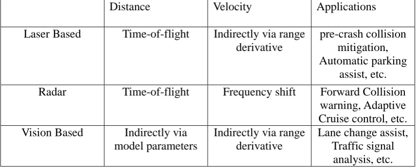
this thesis. Table 1 below summarizes the different sensors with their properties and
applications mentioned above.
Distance Velocity Applications
Laser Based Time-of-flight Indirectly via range derivative
pre-crash collision mitigation, Automatic parking
assist, etc.
Radar Time-of-flight Frequency shift Forward Collision warning, Adaptive Cruise control, etc. Vision Based Indirectly via
model parameters
Indirectly via range derivative
Lane change assist, Traffic signal
analysis, etc.
Table. 1 Summary of the types of sensors used for AV
3.2 ADVANCED DRIVER ASSISTANCE SYSTEMS
The Advanced Driver Assistance systems (ADAS), include the most of the current
existing technologies that assist drivers on road to rely on applications such as
Adaptive cruise control (ACC), Forward collision mitigation, Automatic parking,
Lane change assistance and many more. Currently, all these applications are built to
support partially to the driver. The dependability of these driver assistance systems is
high not only on the current state of the vehicle, but also on the environment that is
constantly changing with respect to time. These conditions are subjected to the type of
sensors used for a particular application. In future, ADAS applications are expected to
rely more on the safety of the passenger by autonomously taking control of the
vehicle as in, autonomous emergency braking, collision avoidance while steering
20 negligence of the driver. Also, what’s more important is the reliability of these
systems built. As the sensors in nature are not accurate a validation system is required
in order to mitigate the false activations of any of the applications whenever they are
not required to function. This may lead to more substantial problems, which account
for the safety of the passenger. More on the ADAS developments and current state of
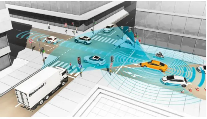
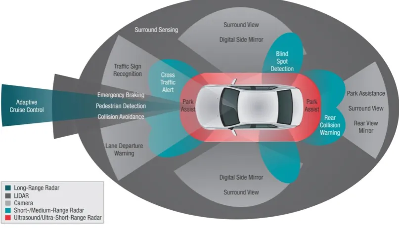
the art can be found in [25]. The figure 10 below shows some of the existing
applications with the types of sensors used in ADAS.
Fig. 10 ADAS applications in use with the different types of sensors 2
21
CHAPTER 4
MULTI SENSOR DATA FUSION
Most of the techniques pertaining to the information fusion were derived from defense
and surveillance applications in the automotive industry. The challenge was to make
the environment perception more robust with increasing confidence and reliability in
order to meet the unpredictable demands of the constantly changing nature of the
AV’s surroundings. Yet, the challenges that are to be met impose few additional
constraints depending on the cost, architectures and types of sensors used. This
chapter introduces to some of the architectures that are commonly accepted by the
data fusion community followed by some of the advantages of using these methods.
4.1 ARCHITECTURES OF MULTI SENSOR DATA
FUSION
Due to the vast majority of applications exist for multi sensor data fusion some to
mention in the field of robotics, defense applications, virtual reality and air traffic
control, the methodology of fusion techniques used is diverse. Many models have
been proposed to achieve this task over the years. Out of all these one of the highly
cited models that is still followed today is the model proposed by U.S based defense
research foundation named Joint Directors of Laborotary (JDL). This model is widely
studied and revised in 2004. The figure 11 below shows the revised JDL model for
data fusion [26].
The JDL model takes into account the abstraction of data at different levels
with respect to fusion. The data can be abstracted at a very early stage as in signal
22 comprises of integration of information from different sources such as sensors,
databases and different layers of data processing called fusion domain along with an
interface for decision system. In automotive industry the fusion domains inherited
from this model can be implemented to achieve the robust description of the
environment. However, there are constraints with respect to cost and complexity of
the design.
Fig. 11 JDL process Model for Data Fusion [26]
For automotive applications two types of fusion paradigms are possible
depending on the level of data abstraction [6]. The low level fusion or signal level
fusion that utilizes the raw sensor data and the high level fusion or so called the
decision level fusion which uses the processed data for fusion of information.
There is the third kind of fusion that takes in the advantages of both high level and
low level called the hybrid fusion or feature level fusion. Each of these fusion
paradigms has certain advantages and disadvantages based on the application and
types of sensors utilized for integration of the information to perceive the
environment. The figure 12 below shows the block diagram of each of these fusion
23
a)
b)
c)
Fig. 12 a) Low-level fusion b) High-Level Fusion c) Hybrid Fusion S0 Sn F u s i o n
Detection Tracking Tracks
S0
Sn
S0
S1
Detection Tracking
Tracks
Detection Tracking
Detection Tracking
Tracks F u s I o n F u s i o n F u s i o n
24
4.2 ADVANTAGES OF MULTI SENSOR DATA FUSION
The design and implementation of data fusion architectures vary from application
and the types of sensors used. Also the field of application is diverse as in data
fusion is used for defense and surveillance, aviation industries, Robotics and
Virtual reality apart from the automotive sector. According to [6], There are nine
benefits of data fusion aiming at two objectives of increased system’s availability
and increases system’s authenticity that define the exactness of the objects
perceived. The sensor arrangements vary in accordance with the objectives. There
can be three different classes of sensor arrangement as shown in figure 13.
Fig. 13 Different classes of sensor arrangements [27]
The following arrangements for fusion objectives are:
Complementary Arrangement: The sensors perceive complimentary
information with advantages of extended spatial coverage, extended temporal
coverage and improves detection.
25 providing redundant data with the advantages of increased dimensionality,
improves system reliability and enhanced spatial resolution.
Collaborative Arrangement: The sensors perceive the environment
collaboratively by providing information that single sensor cannot derive. The
26
CHAPTER 5
PROPOSED METHOD
This chapter gives the overview of the proposed model used for the study
mentioned in the scope of this thesis. Since in literature the problem of MSDF
technique is not uniquely designed however, is studied separately addressing
multiple problems as tracking with detection while few tend to deal with specific
problem as obstacle detection. In the first part of this work a novel technique to
detect the road obstacles for AVs using laser scanner and camera is designed. The
second part focuses on data association and state estimation often termed as multi
target tracking (MTT) with robust track management. In order to estimate the
performance of proposed MTT in terms of different fusion paradigms with varying
sensor combinations, a discrete event simulation analysis model is proposed in the
third part.
5.1 OBSTACLE DETECTION USING COOPERATIVE
FUSION OF LASER SCANNER AND CAMERA
In this section the architecture proposed for the cooperative fusion between laser
scanner and camera sensors is considered. The block diagram given in figure 14
below explains the steps taken towards obstacle detection on road for AV. There are
many sophisticated methods available in literature to do this task considering single
sensor such as camera alone, however the motive here was to explore the
techniques available for laser scanner processing and with the help of this extract
27 work the advantages of this method are discussed with relevant techniques in order
to extend this work. Further sub sections in this part explain each important block
in the proposed architecture.
Fig. 14 Block diagram for cooperative fusion of laser and camera
5.1.1 FEATURE EXTRACTION
Since the objects in world around AVs are made of primitive geometric shapes, due
to the property of laser scanner the reflections of ground objects have information
about local saliencies such as surface normal and curvature at each of the
corresponding 3d location in sensor space. The first preprocessing step involved in
order to make sense of point cloud data obtained is to remove the points belonging
to the road surface by fitting a planar surface which requires estimating of above
mentioned saliencies in each step.
In the field of computer vision literature, methods like Least squares,
Prinicipal Component Analysis (PCA) and Random Sample Consensus (RANSAC) LASER SACNNER
FEATURE EXTRACTION
CLUSTERING
CAMERA FEED
PROJECTION OF LASER POINTS
28 are well known, and are still cited algorithms in order to achieve this task. Some of
the recent works can be found in [28] [29], wherein the work done by nurunabbi et
al gives the analysis of the above mentioned techniques for ground plane detection
and removal. RANSAC is a re-sampling technique which iteratively generates the
candidate solutions into inliers and outliers by using the minimum number of
observations required to estimate the model parameters that fit a plane. If the
fraction of the number of inliers over the total number of points in set exceeds the
predefined threshold T, then the model parameters are re-estimated considering all
the identified inliers and process is terminated. Simple illustration of this method
for 2d line fitting can be seen in figure 15 below.
Fig. 15 Illustration of 2D line fitting technique
Much later in [30], Torr and zisserman showed that in RANSAC if the
threshold T for considering the inliers is set too high then the robust estimate can be
very poor. To over come this they proposed a new estimator called MSAC which
takes as support the log-liklihood of the solution taking into account the distribution
of outliers and uses random sampling to maximize this. Vosselmen and Klien [31]
showed the advantages of using MSAC over RANSAC algorithm for this purpose.
29 belonging to corresponding plane. Figure 16 below illustrates some of the results
applied to the point cloud data.
a) Raw laser point cloud projected on an Image
b) Ground plane detection on the horizontal plane in point cloud data
c) Ground plane removal and projection of laser points on vertical surfaces
Fig. 16 Illustration of Ground plane Detection and removal from point cloud data
5.1.2 CLUSTERING
Once the ground plane is removed, the remaining point clouds belong to road
obstacles which may be coming from vertical plane surfaces such as cars, walls and
clutter objects such as poles and bins on the road. The next step is to classify the
30 points coming from same objects into one is called clustering. The 3D points coming
from laser for each frame may differ in orientation based on the arbitrary shapes. In
order to cluster the data of this type most promising clustering methods include
Graph-theoretic methods which cluster the data based on the neighboring points [32].
In this work one of the kind belonging to this class of methods called DBScan
proposed by ester et al [33] is used.
The advantage of using this algorithm is it does not take into account the prior
initialization of a number of clusters to be formed as in Kmeans. It takes just two
parameters as input specified by the user. The parameters include the search radius
and the minimum number of neighboring points Mp to be considered while
clustering. An illustration of working of this algorithm is shown in figure 17. The
algorithm starts with arbitrary point A and looks for the Mp points in
neighborhood. The new cluster is started if condition is satisfied by marking A as
cluster center and all other points in neighborhood belong to this cluster core. In the
next step Mp neighborhood of all these points is checked and cluster is grown
arbitrarily. The points that do not satisfy this condition are marked as outliers. The
metric used for computation is the euclidean distance between the points. The
complexity of this algorithm isO n log n
, where n is number of points. Worstcase complexity is given byO n
2 .
31
5.1.3 BINARY MASK EXTRACTION
After clustering the laser point clouds, the filtered objects are projected on image
plane using the calibration matrix between laser and camera. The next task is to
extract the region of interest in the image plane, which represent the potential targets
on the road that AV has to identify in order to avoid the collision and accurate path
planning. In order to extract the ROI in image plane a binary mask is created which
search for projected laser points. A NXN scanning window is run across the image
plane, which collects and marks the potential targets. A novel algorithm is proposed to
do this task. The algorithm is depicted below which shows the following steps taken.
The Algorithm
BinMask=False
For i = 1 : N : end of X coordinate For j = 1: N : end of Y coordinate
For k = 1: Size(Projected laser Points) If (in the Image Plane)
Extract Projected Points End
End
If Size(Extract Projected Points) > Threshold BinMask = True
32
5.2 MULTI TARGET TRACKING (MTT)
This section explains the steps taken for the process of multi target tracking which
involves association of multiple detections over the time and updating the believe
of where the objects in space are based on the predictions made on where the
objects are going to move in future frames. The block diagram given below in
figure 18 explains the methodology followed in order to design this system. It is
important to note that the overall system design may vary as there is no uniform
practice followed in the literature.
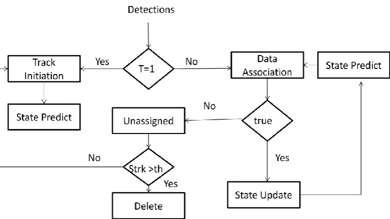
Fig. 18 Block diagram of Multi target tracker
5.2.1 DATA ASSOCIATION
In the case of MTT while maintaining the states of multiple occurrences of targets,
what’s important is to assign the measurements coming from particular targets to
33 information required to do this task is the detected features of the targets and the
predicted states that come from the filtering step. Figure 19 below illustrates the
association of three predicted states to the five measurements which clearly depicts
the linkage between previous to the current time step.
In literature, there are many techniques to achieve this task, some of the
commonly used methods for applications in the automotive field are Global
Nearest Neighbors (GNN) [34], Multiple Hypothesis Tracker (MHT) [35] and Joint
Probabilistic Data Association (JPDA) [36]. In this study GNN algorithm has been
used to do the associations which take the distance between predicted states and
measured data and globally optimizes the solutions to find the match between the
last iteration in order to update the states in filtering step. The steps taken in order
to make the correct associations are explained below
Fig. 19 Illustration of Data Association Process
Consider the two sets of data that’s required for the association. Let Z be the
34 measurements. Let X be the predicted target states where xj= 0,1,2,..n-1 with n
being the number of tracks. Now, the problem of data association can be
formulated to find the Assignment matrix M that minimizes the cost function
given in equation 5.1 and 5.2 which evaluates the cost of assigning each predicted
state j to their respective measurement i, with the distance d( , j)i . In order to
solve this linear assignment problem Hungarian algorithm is used.
1 1 0 0
(
)
( , )
m n ij i jf M
m d i j
(5.1)
Where, (5.2)
1 0
{
m
The above equations hold true subjected to the following constraints given in
equation 5.3 and 5.4 which follow the general rule of data association to ensure that
every measurement gets assigned to exactly one predicted track and every predicted
state gets assigned to at most, one measurement respectively.
1
0
1,
, 0,1,..
1
mij i
m
j
n
(5.3)And
1
0
1,
, 0,1,..m 1
n ij j
m
i
(5.4) if zi assigned toxj35
5.2.2 STATE ESTIMATION
While maintaining the states of targets based on sensor measurements, due to the
irregularities and noise subjected to sensors and clutter it becomes difficult to deduce
the true nature of the environment. In order to overcome this a proper, timely
correlation of knowledge about the world has to be maintained as tracks by
eliminating the noise making sure the estimates are close to the real entities. The
target states of interest include the position and velocity of the objects at every time
step. The process includes two iterative steps: state update /correction and state
prediction. The figure 20 below shows one of the example scenarios depicting the
workflow of these kind of filters.
Fig. 20 Illustration of Kalman Filtering Process
In literature, most common methods adopted to achieve this task include
Kalman filtering, extended Kalman filtering and particle filters [37]. Application of
36 assumptions, such as the if the motion model is linear then Kalman filter is used and
for non linear noise, particle filter and extended Kalman filters and its variants are
used. Each has its own advantages and disadvantages in terms of a tradeoff between
memory requirements and accuracy of the performance. For this proposed
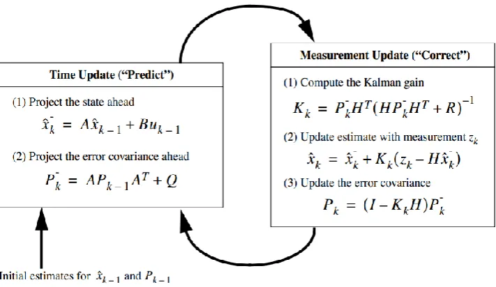
architecture, Kalman filter is used for accurate state estimation.
The design of Kalman filter includes the three steps: Initialization, State
prediction and state update / correction. In the initialization step all the required filter
parameters such as state estimate xˆk and covariance matrix Pk are set to initial
values. The equations used for calculation of prediction and correction are depicted in
figure 21 below.
Fig. 21 Steps involved in Kalman Filtering with equations
5.2.3 TRACK MANAGEMENT
The above mentioned techniques of data association and state estimation cannot
perform individually, without the assistance of the robust track management module.
The main functionality of this module is to check for the newly entered objects in the
37 also helps to identify the lost tracks for a couple of frames in the case of short missing
instances of sensor data. The performance of the overall tracker depends on the
decisions made here as the unwanted tracks may lead to exhaustive memory drain in
the processor while failure to assign new tracks may lead to loss of information.
There are many ways one can design this system which may vary over the
chosen algorithms for data association and the type of state estimation done. Just to
mention a few examples, some methods take decisions based on track survival
probability such as in [35], while another type includes checking the entropy or the
information content as shown by [38]. In this thesis the decision module is built by
choosing the heuristic approach to check for unassigned tracks after association so as
to fit the randomness of the chosen data set. The unassigned tracks which do not get
assigned to any of the measurements are given the strike rate, which keeps in count
the number of frames, a particular track is idle. If the strike rate exceeds the selected
threshold, then the track is deleted. Also, this module checks if any new targets have
entered by scanning the past consecutive frames in order to initialize new tracks.
5.3 SIMULATION MODEL
Usually while designing the MSDF system, it gets difficult to evaluate the algorithms
due to the plethora of architectures and sensor systems available. It is not feasible to
test all the combinations of sensory systems in all the environment. In order to fill this
gap a simulation analysis model is presented which gives the flexibility to the user to
evaluate the architectures with different fusion paradigms.
The simulation model designed incorporates the different sensor models with
varying detection probabilities. The model can be extended to fit the purpose of
38 data association techniques which are the core of any fusion paradigms. The aim here
is to generate the random trajectories of the targets. This could be sensed by the
sensors employed and the data is fused with different fusion paradigms. The figure 22
below shows the core of the simulation engine proposed for this thesis.
Fig. 22 Block diagram of simulation model
The figure 23 explains the way low level and high level architectures are
designed for this simulation analysis.
a) Low level Fusion b) High level Fusion
Fig. 23 Block diagram of fusion architectures Trajectory Generator S1 S2 S y n c r o n i z e Low Level Fusion High Level Fusion Evaluation
S1 S2
fusion
MTT
Tracks
S1 S2
MTT MTT
fusion
39 The sensor set’s used for the simulation can be found in table 2 below. This
includes Laser scanner (LS), long range radar(LRR), short range radar(SRR) and
Lidar.
Sensors Range Azimuth Variance
in X
Variance
in Y
LRR 120 10 0.45 0.15
SRR 40 60 0.5 0.2
LS 100 100 0.11 0.11
LIDAR 120 10 0.15 0.15
Table. 2 Types of Sensors used for simulation
The screenshot of one of the scenes, including the laser scanner and Long
range radar can be seen in figure 24. The interface was built in python and as it can be
seen in the figure, the red color box represents the ego-vehicle, while the blue and
yellow color regions define the field of view of LS and LRR respectively. The blue
boxes represent the targets in the scene while the black dots represent the error in
detection with the circles on edge representing the detected positions (x, y) of the
corresponding targets.
40
CHAPTER 6
EXPERIMENTS AND RESULTS
This chapter provides the details of the evaluation made on the proposed
architectures using real time and simulated sensor data. All the experiments were
conducted on 2.4 GHz microprocessor running windows 7 Operating System using
MATLAB and python for simulation interface. The assumptions made for the
experiments and the metrics used is addressed in following sub-sections of this
chapter. The purpose of the experiments was focused, keeping in mind answering
three different research problems: detection, data association and Optimal Filtering.
In the first part focus of study is to detect the potential road obstacles while the
second part deals with predicting where the obstacles fall and updating the states
based on detections obtained. The third problem, in fact the most important is the
evaluation of how well the proposed multi target tracker performs with different
fusion paradigms using discrete event simulation analysis.
6.1
COOPERATIVE FUSION RESULTS
For this experiment the registered sensor data from laser scanner and camera are
considered. In order to do the clustering neighbors considered to be 5. If the nearest
neighbors considered are larger, then the algorithm tends to misclassify the clusters
which may be coming from the wall or pole. Also, for the proposed ROI extraction
the window size chosen was 50X50. The values for neighbors and window size has
been heuristically chosen and the performance of the algorithm can be seen in
figure 25. The analysis shows the instances where the obstacles have been precisely
41
a) Frame 1
b) Frame 2
42
c) Frame 3
d) Frame 4
43
6.2 MULTI TARGET TRACKING
For Optimal filtering we considered the constant velocity model which assumes the
linear Gaussian noise in nature. The evaluation metrics used and visual results are
shown in the figures below.
6.2.1 EVALUATION METRICS
The metrics used to evaluate the proposed multi target tracker considering the
ground truth values from the KITTI data set [39] are Recall, Precision, F-measure
and False Positive rate.
Recall is also known as detection rate which gives the percentage of detected
true positives as compared to the total number of true positives in the ground truth
Re
(
)
tp
call
tp
fn
Where, tp is the number of true positives, fn is the total number of false
negatives. Along with recall, the other metric used is Precesion, which gives
positive prediction. Which represents the percentage of detected true positives as
compared to the total number of objects detected.
Pr
(
)
tp
ecision
tp
fp
Where, fp is false positive. The method is considered good if Recall is high
without sacfricing Precesion. The weighted harmonic mean of these two metrics is
taken and called as F-measure or figure of merit. Given by,
2.Re
.Pr
(Re
Pr
)
call
ecision
F
measure
call
ecision
44 objects detected in the scene. This should usually be low as compared to all the
above in order for the method to be considered as good.
(
)
tp
Falsepositiverate
tp
fn
fp
For the evaluation two scene sequences are considered. The first sequence
consists of the pedestrians and cyclists crossing the road with lots of occlusions and
for the second sequence, the traffic junction scenario is considered which is
45
6.2.2
VISUAL RESULTS
a) For sequence 1
a) Frame 153
b) Frame 154
c) Frame 155
d) Frame 156
e) Frame 157
f) Frame 158
46 b) For Sequence 2
a) Frame 52
b) Frame 65
c) Frame 84
d) Frame 103
e) Frame 112
f) Frame 132
g) Frame 139
47
6.2.3
QUANTITATIVE RESULTS
a) For Sequence 1
b) For Sequence 2
48
6.3
SIMULATION RESULTS
6.3.1
FOR SENSOR SET 1- LRR & SRR
a) Low Level Fusion
b) High Level Fusion
Fig. 29 Simulation Results for sensor set 1 Y-position X-position
49
6.3.2
FOR SENSOR SET 2- LS & LRR
a) Low Level Fusion
b) High Level Fusion
Fig. 30 Simulation Results for sensor set 2 X-position Y-position
50
6.3.3
FOR SENSOR SET 3- LIDAR & SRR
a) Low Level Fusion
b) High Level Fusion
Fig. 31 Simulation Results for sensor set 3
X-position Y-position
51
6.3.4
FOR SENSOR SET 4- LS & SRR
a) Low Level Fusion
b) High Level Fusion
![Fig. 1 Canada’s 2008 Road safety ranking among OECD Member Countries [1]](https://thumb-us.123doks.com/thumbv2/123dok_us/1392215.1171924/13.595.122.514.448.667/fig-canada-road-safety-ranking-oecd-member-countries.webp)
![Fig. 3 Timeline summarizing the impact of autonomous vehicles on transport system [3]](https://thumb-us.123doks.com/thumbv2/123dok_us/1392215.1171924/16.595.120.521.569.724/fig-timeline-summarizing-impact-autonomous-vehicles-transport.webp)
![Fig. 4 Illustrations of different fusion paradigms adopted by ProFusion group [8]](https://thumb-us.123doks.com/thumbv2/123dok_us/1392215.1171924/20.595.177.470.431.652/fig-illustrations-different-fusion-paradigms-adopted-profusion-group.webp)
![Fig. 11 JDL process Model for Data Fusion [26]](https://thumb-us.123doks.com/thumbv2/123dok_us/1392215.1171924/34.595.158.455.241.435/fig-jdl-process-model-for-data-fusion.webp)