Division II
Export Classified – ‘Not Listed’ © Copyright Rolls-Royce plc 2017. All rights reserved.
DEVELOPMENTS IN ENVIRONMENTALLY ASSISTED FATIGUE
METHODOLOGIES
Keith Wright1
1
Chief Stress Engineer & Associate Fellow Structural Integrity, Rolls-Royce, UK
Chair of ASME Working Group on Environmental Fatigue Evaluation Methods (2012-2017)
ABSTRACT
The American Society of Mechanical Engineers (ASME) Working Group on Environmental Fatigue Evaluation Methods (WGEFEM) has proposed in a fatigue action plan a number of methodologies with an increasing degree of complexity for the engineer to assess Nuclear Power Plant (NPP) components exposed to PWR or BWR reactor water environment. In particular components of austenitic stainless steel are those of main interest due to changes in the ASME air fatigue design curve in 2009 and the realisation that a PWR environment also has a detrimental effect on the fatigue crack growth behaviour.
This paper introduces the reasoning behind the fatigue action plan and the developments that have occurred due to international collaboration in a number of forums over the last few years.
An improvement in understanding of the translation of knowledge to plant representative components and
loading conditions, compared to that originally provided in NuReg/CR-6909 by Chopra and Shack
(2007), provides an opportunity for a reduction in conservatism that would otherwise have more severely penalised NPP designers and component inspection intervals.
A vision for the future developments, including a total life approach to fatigue assessments and the use of target reliabilities as an acceptance criterion, is described.
INTRODUCTION
In the nuclear industry the concept of design by analysis was introduced in the 1960s with the development of the ASME Section III Boiler and Pressure Vessel Code. A number of novel methods were introduced at that time including strain based fatigue design curves for pressure vessels. Prior to then it was assumed that fatigue was not an issue for pressure vessels due to the relatively low number of stress cycles seen in service compared to, say, rotational machinery components.
The fatigue curves developed from polished, small scale, strain controlled specimen tests in air were adjusted by design factors applied to both pseudo-stress (strain multiplied by Young’s Modulus) and cycles to account for uncertainties in scatter, size effects, surface finish and, of course, environment. These were not safety factors but transference factors for application of fatigue design curves to large scale vessels. ASME undertook scale vessel tests, Kooistra et al. (1964), which were used to confirm that the design curves were appropriate for use. These cyclic pressure tests used water as a medium albeit at ambient temperature conditions. Many years later it was claimed that the translational factor for environment was only for in-situ air conditions versus laboratory air conditions, Cooper (1992).
Export Classified – ‘Not Listed’ © Copyright Rolls-Royce plc 2017. All rights reserved.
necessity, led to improvements in experimental, analytical and mechanistic understanding. This paper sets out to summarise some of these improvements as well as further aspirations for future developments.
BACKGROUND
In the four decades following the introduction of the original ASME fatigue design curves, further work to understand fatigue behaviour revealed the detrimental effect of a PWR (and BWR) reactor water environment on small scale specimens, and the sensitivity to temperature and strain rate in particular. Work undertaken in Japan and the USA (TENPES and PVRC) showed, for austenitic stainless steels, that
at temperatures of around 300°C and strain rates of <0.004s-1 specimen lives were being reduced by over
an order of magnitude. Whilst this provided many opportunities for the academic community to undertake research, the industry and the codes and standards community were unable to reach consensus on an appropriate way forward.
A contributing factor to the lack of consensus was the argument that the pressure vessel fatigue design curves and the ASME Section III methods for fatigue were never intended to be precise predictors of cyclic life but rather a demonstration of fitness-for-purpose that a design was suitable for construction.
Nevertheless, the United States Nuclear Regulatory Commission (US NRC) regulatory body eventually lost patience with this lack of consensus and in 2007 published NuReg/CR-6909 and the associated Regulatory Guidance RG-1.207 that said, in layman’s language:
“If you want to apply for any new build or license renewals then you are expected to consider environmental effects in a way similar to that prescribed by NuReg/CR-6909.”
The timing of these developments, co-incident with the supposed dawning of an eagerly awaited nuclear renaissance worldwide, had cast a significant shadow across the international community.
INDUSTRY RESPONSE
Whilst most of the major players in the nuclear industry were for many years maintaining a watching brief on developments with this issue, the publication of NuReg/CR-6909 provided the catalyst for a more pro-active involvement due to the potential impact not only on new designs, but also on the management of in-service existing designs.
Within ASME the initial response was to attempt to wrest control back to the codes and standards community via publication of two code cases N-761, ASME (2010) and N-792-1, ASME (2012). However, these were largely based on NuReg/CR-6909 and offered no real improvement in terms of longer cyclic life.
The involvement of the Electric Power Research Institute (EPRI) on behalf of the industry members led to the formation of an expert panel and focus group which generated a gap analysis and roadmap for future research activities, Midmore and Tice (2011 and 2012).
At around the same time as the publication of the EPRI roadmap, ASME took the step to create a new Section III working group; this was named the Working Group on Environmental Fatigue Evaluation Methods (WGEFEM). The brief for this WGEFEM is summarised by the following charter that was agreed by the ASME Section III main committee:
Export Classified – ‘Not Listed’ © Copyright Rolls-Royce plc 2017. All rights reserved.
traditional fatigue usage evaluations, crack growth evaluation and other approaches to provide appropriate design margins when a usage factor or an equivalent criterion is determined.
The wording of the charter was deliberate and provoking in a number of ways to recognise that change was necessary in the way that the issue of fatigue was to be treated in the traditional world of Section III code space. For those not familiar with the nuances of the organisation of the ASME codes and standards, and the regulatory framework in which they are used, some explanation is necessary. Section III relates to design and construction of nuclear facility components, whereas Section XI relates to in-service inspection and operation. Hence, whilst Section XI provides rules for flaw assessment and acceptance criteria in the case of existing plant, Section III is aimed at the design and manufacture of new plant where the perception is that flaws are not permitted and many, including the US NRC, have stated that the purpose of the fatigue design criteria is to protect against the initiation of flaws. However, contrary to this way of thinking, ASME Section III Appendix II permits the use of experimental stress analysis for substantiation where the theoretical analysis is inadequate, including the use of fatigue tests to evaluate the adequacy of a component or portion thereof for cyclic loading. This contradicts the perception that Section III is required to protect against the initiation of flaws as paragraph II-1520 defines failure in a test as propagation of a crack through the entire thickness, such as would produce a measurable leak in a pressure retaining member. Within the Appendix II approach, the allowable operational life is obtained by dividing the minimum test life by a design factor, which is not less than 2.6 and is dependent upon the number of replicate tests and how representative the test conditions are of the component/plant conditions. A factor of 2.6 on life to leakage is unlikely to protect against the initiation of a flaw, particularly when the feature tested has a through wall strain gradient arising from an internal stress concentration feature or the dominant loading is from thermal shocks.
It is accepted that the perception of the protection against the initiation of flaws also assumes conservatism in the analytical methods. But if the analytical methods and fatigue design curve transference factors are deemed accurate, and the component is subject to cyclic membrane loading, then the use of a design curve (from test results using this 25% load drop criterion on specimens with gauge diameters between 5.1mm to 9.5mm) could be considered to suggest that, on average, an ‘engineering crack’ of 3mm depth in a component would equate to a fatigue usage factor of unity. However, this is conveniently considered by Section III to be ‘flaw free’.
Therefore, inclusion of the words ‘crack growth’ into the charter for a Section III working group was seen as a paradigm shift by the conventional and established code-using community. Other innovations included recognising that the traditional design margins, and indeed the acceptance criterion itself, were in need of review.
The WGEFEM have been meeting quarterly since 2012 at the ASME boiler code week meetings. The roster of members and the minutes of meetings are accessible via the ASME “csconnect” system for those with member log-in access, or via request to the applicable ASME staff secretary.
PLAN OF PROPOSED METHODOLOGIES FOR EAF
The overall objective of the WGEFEM fatigue action plan was to identify a series of tasks that would result in an update of methods into Section III to enable appropriate consideration of reactor water environment in the prediction of component fatigue life in a manner acceptable to the regulatory authorities.
Export Classified – ‘Not Listed’ © Copyright Rolls-Royce plc 2017. All rights reserved.
likely to be more load following in operation and hence the subject of increased transient frequencies. The development of methods was required in order to consider reductions in areas of conservatism, for example those due to simplifying assumptions, provided that improved understanding could be validated.
The vision of the WGEFEM action plan is to enable the analysis effort for considering environmental fatigue effects to be minimised by provision of various fit-for-purpose methods. The range of methods included in the plan recognises the potential need to justify components for longer service lifetimes and that the cyclic demands of base load operation versus load following operation are significantly different. A series of methods, with increasing degrees of complexity to enable benefit from increasing reductions in conservatism, are to be provided for the engineer. This staged approach, arguably from the most simplistic to the most complex, is shown in Table 1.
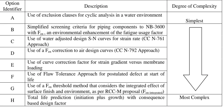
Table 1: Overview of WGEFEM Fatigue Action Plan.
Option
Identifier Description Degree of Complexity
A Use of exclusion clauses for cyclic analysis in a water environment
Simplest
B Simplified screening criteria for piping components to NB-3600
with Fen , an environmental enhancement of the fatigue usage factor
C Use of water adjusted design S-N curves for strain rate (CC N-761
Approach)
D Use of a Fen correction to air design curves (CC N-792 Approach)
E Use of curve correction factor for strain gradient versus membrane
loading
F Use of Flaw Tolerance Approach for postulated defect at start of
life
G Use of a Fen threshold method that considers the integrated effect of
surface finish and environment, as per RCC-M proposal (Fen-integrated)
H Total life prediction (initiation plus growth) with consequence
based design factor
Most Complex
Options A to D from Table 1 would result in evaluations of fatigue life with potentially no reductions in conservatism, compared to NuReg/CR-6909, but may still be adequate in some cases. Options E to H are for where conservatism is required to be removed from the fatigue life assessment of the most limiting components. Hence most effort to date has been concentrated in these latter four approaches.
The ultimate goal is to provide a non-mandatory ASME appendix on the evaluation of environmental fatigue, with guidelines based on the various code cases to be developed in the interim.
FATIGUE ACTION PLAN – SUPPORTING ACTIVITIES
Export Classified – ‘Not Listed’ © Copyright Rolls-Royce plc 2017. All rights reserved.
Some activities have been identified that are the responsibility of other ASME working groups but have been included in Table 2 for completeness. For example, simplified plasticity correction factors (item 18 of Table 2) are the remit of Working Group Design Methodologies (WGDM) and fatigue design curve transference factors (item 13 of Table 2) are the remit of Working Group Fatigue Strength (WGFS).
In parallel to the ASME WGEFEM fatigue action plan, other international bodies have also identified plans for addressing fatigue issues including the harmonisation of fatigue methods by the Standards Development Organisations, Faidy (2016). There is an ongoing effort to rationalise the various fatigue plans that exist into a single plan but, at face value, it appears that they address similar gaps and overlap in the majority of cases.
The WGEFEM fatigue action plan was subject to an ASME comment and review ballot in 2014 which showed that members were supportive of its aim but, not surprisingly, also recognised that it was ambitious and a long-term undertaking that requires significant effort to bring to fruition.
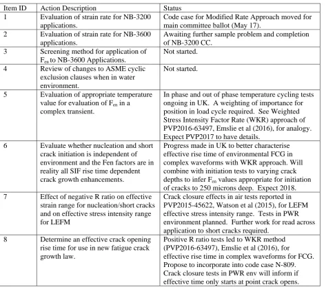
Table 2: Supporting Activities of WGEFEM Fatigue Action Plan.
Item ID Action Description Status
1 Evaluation of strain rate for NB-3200
applications.
Code case for Modified Rate Approach moved for main committee ballot (May 17).
2 Evaluation of strain rate for NB-3600
applications.
Awaiting further sample problem and completion of NB-3200 CC.
3 Screening method for application of
Fen to NB-3600 Applications.
Not started.
4 Review of changes to ASME cyclic
exclusion clauses when in water environment.
Not started.
5 Evaluation of appropriate temperature
value for evaluation of Fen in a
complex transient.
In phase and out of phase temperature cycling tests ongoing in UK. A weighting of importance for position in load cycle required. See Weighted Stress Intensity Factor Rate (WKR) approach of PVP2016-63497, Emslie et al (2016), for analogy. Expect PVP2017 to have details.
6 Evaluate whether nucleation and short
crack initiation is independent of environment and the Fen factors are in reality all SIF rise time dependent crack growth enhancements.
Progress made in UK to better characterise effective rise time of environmental FCG in complex waveforms with WKR approach. Will combine with initiation tests to varying crack
depths to infer Fen values appropriate for initiation
of cracks to 250 microns deep. Expect 2018.
7 Effect of negative R ratio on effective
strain range for nucleation/short cracks and on effective stress intensity range for LEFM
Crack closure effects in air tests reported in PVP2015-45622, Watson et al (2015), for LEFM effective stress intensity range. Tests in PWR environment planned. Further work for read across application to short cracks required.
8 Determine an effective crack opening
rise time for use in new fatigue crack growth law.
Positive R ratio tests led to WKR method (PVP2016-63497), Emslie et al (2016), for
Export Classified – ‘Not Listed’ © Copyright Rolls-Royce plc 2017. All rights reserved.
Table 2 (continued): Supporting Activities of WGEFEM Fatigue Action Plan.
Item ID Action Description Status
9 Hold time effect on effective crack
opening rise and its dependence on the stress magnitude at which it occurs.
WKR method (PVP2017-65645), Emslie et al (2017), derives an effective rise time. Holds in lower portion of load cycle much less significant than holds in upper half of load cycle. Empirical use of 1000 psi/hour below which N-809 assumes ‘steady state reached’ is arbitrary.
10 Hold time effect on ability of
protective oxide layer to repair and reform.
No progress. Will need experimental programme and may prove very difficult to take advantage of in design. Analogy to retardation of FCG in high S steels. Ratio of benefit/expense judged low so propose it is a long term and low priority item.
11 Hold time effect at high temperature
for introducing material hardening that would only gradually soften during subsequent cycling (AdFaM project).
European AdFaM project nearing completion. For stabilised stainless steels indicates a benefit in enhancing life by maybe 30% but difficulty in how to claim use of the benefit in safety case other than a defence-in-depth margin.
12 Appropriate cycle counting
methodology for variable amplitude loading and with localised plasticity.
See WRC Bulletin, WRC 550 – “Standardization of Fatigue Methods for use in API 579-1 / ASME FFS-1”
13 Re-appraisal of fatigue design
transference factors to result in an appropriate safe life prediction for a specific target reliability value. (see Item ID 20).
French work published on reducing design factor on strain from 2 to 1.4 on 304 grade material. Integrated effect of surface finish and PWR environment also not as severe as when considered independently. Debate on definition of end-of-life ongoing. Raised in paper, Wright (2016),
presented at IAEA Technical Meeting on Fatigue Assessment, July 2016. Now picked up by WGFS and need for clarity from ASME in updated criteria document essential.
14 Component feature validation testing
for benchmarking revised analytical procedure.
Discussion with EPRI held to develop a Request For Proposal to put to interested parties in 2017. Consider use of results for round robin predictions by industry. Would be enhancement from ‘stepped pipe’ thermal shock tests that have been relied upon to date. Overview provided by PVP2017-65995, Steininger et al (2017).
15 Guidance on effect of through wall
strain gradients and total life prediction. (see also Item ID 21 and 22).
Work with EPRI to evaluate analytical benefit of simple linear strain gradients in piping components and consideration of 25% load drop criteria in thicker walled components to enable allowable end of life crack depths greater than 3mm to be
Export Classified – ‘Not Listed’ © Copyright Rolls-Royce plc 2017. All rights reserved.
Table 2 (continued): Supporting Activities of WGEFEM Fatigue Action Plan.
Item ID Action Description Status
16 When a fatigue crack initiation
(stage I) life is combined with a fracture mechanics (stage II) life guidance is required to define the crack size and shape assumed when transitioning between methods. This would depend on the type of loading and extent of the stress field.
For a thermal shock loading then a large surface area may be susceptible to thermal crazing. The eventual formation of a single dominant crack is likely to be due to the coalescence of several smaller initiated cracks.
The draft Flaw Tolerance Code Case assumes postulated semi-elliptical surface flaws of at least 6:1 (surface half length to depth ratio). But where the wall thickness reduces and/or the membrane-to-gradient stress ratio reduces then a more severe aspect ratio is assumed tending towards extended. Where the stress field is localizes a smaller aspect ratio is permitted if justified on a case by case basis.
17 Procedure for where plastic analysis is
required to evaluate strain ranges for fatigue analysis – remit of WGDM.
Initial work provided at WGEFEM meeting May 2014 for EAF analysis using NL FEA. More recent proposal on plastic strain measure for discussion with WGFS.
18 Derivation of less conservative
plasticity correction factors for Ke and
Kmu – remit of WGDM.
EPRI have done some work recently. Various PVP papers all state ASME approach excessively conservative.
19 Watching brief on Fatigue Resistant
Design proposals from WG Piping.
20 Methodology for deriving target
reliabilities against which fatigue predictions need to be made.
Consequences of leakage occurring at particular locations to dictate
reliability target.
Special Working Group on Reliability and Integrity Management (SWG RIM (BPV XI) ) have
introduced concept of reverse engineering the plant probabilistic risk assessment (PRA) to evaluate reliability targets. Methodology required to harmonise an approach for plant designs with varying degree of plant protection systems. See IAEA paper, Wright (2016).
21 Flaw Tolerance Method to take
advantage of strain gradient effect
Draft code case developed which assumes a start of life postulated defect in the event of extant fatigue methodologies being unable to demonstrate a FUF of less than unity. Sample problem detailed in PVP2014-28788, Dewees et al (2014).
22 Total Life Methodology to combine
Nucleation and Stage I life and to take advantage of strain gradient in Stage II life yet still satisfy required target reliability for avoidance of through wall leakage.
This is the gold standard end objective which draws upon enhanced knowledge from majority of sub-tasks above. A fit-for-purpose model that is validated by adequate component feature testing would enable simpler screening options to be developed with quantified margins for plant representative complex loading conditions.
23 Fen Integrated Code Case See presentation at Nov 2016 WGEFEM. Details
Export Classified – ‘Not Listed’ © Copyright Rolls-Royce plc 2017. All rights reserved. DISCUSSION
The reasoning behind the fatigue action plan is to provide a series of staged options of assessment methods for environmental fatigue; from the simple and cheap to the more complex and expensive, albeit less conservative, where deemed necessary. Progress has been made on a broad front of activities that will contribute to the delivery of options E to H in Table 1, which are all less conservative than the approach of NuReg/CR-6909.
The critical path activities are all, to differing degrees, dependent upon testing to improve understanding. Testing in a pressurised hot PWR environment using non-isothermal complex loading waveforms that are more representative of plant conditions is key to unlocking the conservatisms that exist in NuReg/CR-6909. Understandably this testing is difficult and time-consuming so the impression can easily be obtained that progress is slow.
However, an improvement in the understanding of environmental fatigue crack growth is one of the notable successes so far. In particular the weighted stress intensity factor rate (WKR) approach, Emslie et al (2016), significantly aids the reconciliation of complex plant representative loading waveforms to data from simple laboratory sawtooth loading waveforms. This will help underpin future developments because the less conservative options E, F and H of Table 1 all require a consideration of fatigue crack growth effects.
For option E of Table 1, the effect of a strain gradient, albeit for carbon steel piping components, has been considered in terms of stage I and stage II crack growth compared to conventional membrane loading, Gosselin et al (2016). This has shown the potential for enhanced lifetimes independent of environmental considerations that can offset to a certain degree the penalty of environmental effects even when limiting the allowable fatigue crack growth to a depth corresponding to a 25% load drop for strain controlled conditions.
Option F of Table 1 for the flaw tolerance approach has been developed into a draft code case with supporting technical basis document and sample problem technical paper, Dewees et al (2014). Currently this approach requires some ballot disapprovals to be resolved despite a majority of voting members being in favour. The common theme from most of the disapprovals received is centred on accepting that a fatigue usage factor may exceed unity. In brief, the flaw tolerance approach is only intended for use when the fatigue usage factor is above unity when the effects of environment are included, but would have been less than or equal to unity without the effects of reactor water environment. The code case requires that an initial flaw be postulated, but this is solely for determining the flaw tolerance. Nothing in the draft code case relaxes Section III requirements which prohibit such flaws.
However, despite only being a postulated flaw and assuming it to be present from start of life, even though it can be shown in certain cases not to propagate a significant distance through wall and still maintain an end of life margin comparable to Section XI requirements, it is still not currently seen as being acceptable to some in Section III. In the author’s opinion, this objection is related to the traditional ASME ways of thinking and the demarcation between Section III and Section XI as discussed earlier in this paper. It is hoped that these negative opinions may be resolved and overcome in the near future.
Option G of Table 1 refers to the Fen threshold approach that has also been developed into a draft code
Export Classified – ‘Not Listed’ © Copyright Rolls-Royce plc 2017. All rights reserved.
equivalent to an environmental enhancement on fatigue usage factor (Fen factor) of 3.0, Métais et al
(2015).
Finally, option H of Table 1 proposes a total life approach, Wright (2016). This remains the least developed option at present but, in practice, it is technically no more demanding with the proviso that two key aspects are addressed.
First and foremost the question of what is an adequate margin against the possibility of through wall leakage occurring needs to be understood, recognising the potential consequences were it to occur. The concept of using target reliability as an acceptance criterion for fatigue, Wright (2017), is not new and has been successfully employed in other non-nuclear industries, Beratta (2015).
In the nuclear industry there is an idea to reverse engineer the probabilistic risk assessment (PRA) so that component level target reliabilities can be derived. These would enable a meaningful and quantified margin, aligned to and calibrated against a target reliability, to be imposed and would provide a major leap of progress compared to relying upon the judged appropriateness of the fatigue design curves from the scale vessel tests of 1964.
Secondly, it becomes necessary for improved component feature testing under plant representative loading and environmental conditions to be undertaken (item 14 of Table 2) to benchmark against the more realistic total life analytical approaches. Proposals for such testing have been described, Steininger et al (2017), and are being pursued by EPRI and others internationally.
Deterministic total life approaches, where a partial safety factor on life prediction is calibrated to a required target reliability, would provide the gold standard approach to be drawn upon in extreme circumstances for the most limiting of components subject to detrimental environmental fatigue conditions.
CONCLUSIONS
The nuclear industry is now significantly more informed about reactor water environmentally assisted fatigue and fatigue crack growth and the industry should seek to take credit and benefit from this.
Progress in proposed developments by the ASME WGEFEM community and others are ongoing to enable various staged options of improved fatigue evaluation methods to be drawn upon in the design and through-life substantiation stages of NPP components when deemed necessary.
Achievement of a total life approach with an understanding of appropriate target reliabilities will enable the current unquantified margins in fatigue design to be challenged and permit the potential trading of margins to be considered in the optimisation of future NPP designs, even in the presence of a detrimental reactor water environment.
ACKNOWLEDGEMENTS
To past and present members of ASME WGEFEM thank you for your support.
REFERENCES
ASME, (2010), “Fatigue Design Curves for Light Water Reactor (LWR) Environments, Section III,
Division I”, Case N-761, ASME Boiler and Pressure Vessel Code. Code Cases Nuclear
Export Classified – ‘Not Listed’ © Copyright Rolls-Royce plc 2017. All rights reserved.
ASME, (2012), “Fatigue Evaluations including Environmental Effects, Section III, Division I”, Case
N-792-1, ASME Boiler and Pressure Vessel Code. Code Cases Nuclear Components, ASME, USA.
Beretta, S. and Regazzi, D. (2016). “Probabilistic fatigue assessment for railway axles and derivation of a
simple format for damage calculations”, International Journal of Fatigue, Vol. 86, 2016, pp13-23.
Chopra, O., and Shack, W. (2007). Effect of LWR Coolant Environments on the Fatigue Life of Reactor
Materials, NUREG/CR-6909, Argonne National Laboratory.
Cooper, W.E. (1992). The Initial Scope and Intent of the Section III Fatigue Design Procedures, PVRC
Workshop on Environmental Effects on Fatigue Performance, Clearwater Beach, FL, USA.
Dewees, D.J., Hirschberg, P., Reinhardt, W., Stevens, G.L., Roarty, D.H., Gosselin, S., Wright, K. and Damiani, T.M. (2014). “ASME Section III Flaw Tolerance Sample Problem for Fatigue Design of
Nuclear System Components”, PVP2014-28788, Proc., ASME 2014 Pressure Vessels and Piping
Conference, Anaheim, California, USA.
Emslie, J., Gill, C. and Wright, K. (2016) “Assessment Method to Account for the Rise Time of Complex Waveforms in Stainless Steel Environmental Fatigue Crack Growth Calculations”,
PVP2016-63497, Proceedings of the ASME 2016 Pressure Vessels and Piping Conference, Vancouver,
British Columbia, Canada.
Emslie, J., Cruchley, S., Currie, C. and Wright, K. (2017). “Further Validation of the Weighted Stress Intensity Factor Rate (WKR) Method for Stainless Steel Pressurised Water Reactor Fatigue Crack Growth Calculations”, PVP2017-65645, Proceedings of the ASME 2017 Pressure Vessels and Piping Conference, Waikoloa, Hawaii, USA.
Faidy, C., Shi, J., Wasylyk, A., Wei, L. and Prinja, N. (2016). “A Comparison of Different Design Codes on Fatigue Life Assessment Methods”, PVP2016-63040, Proceedings of the ASME 2016 Pressure Vessels and Piping Conference, Vancouver, British Columbia, Canada.
Gosselin, S.R., Nunez, D., Esselman, T.C. and Palm, N. (2016). “Fatigue Usage Life and Gradient
Factors for ASME Class 1 Piping Fatigue Analyses”, PVP2016-63027 R1, Proc., ASME 2016
Pressure Vessels and Piping Conference, Vancouver, BC, Canada.
Kooistra, L.F., Lange, E.A. and Pickett, A.G. (1964). “Full-Size Pressure Vessel Testing and Its
Application to Design”, Journal of Engineering for Power, ASME, USA.
Midmore, L. and Tice, D. (2012). Environmentally Assisted Fatigue Gap Analysis and Roadmap for
Future Research – Roadmap, EPRI 1026724.
Midmore, L. and Tice, D. (2011). Environmentally Assisted Fatigue Gap Analysis and Roadmap for
Future Research – Gap Analysis, EPRI 1023012.
Métais, T., Courtin, S., Genette, P., De Baglion, L., Gourdin, C and Le Roux, J.C. (2015). “Overview of French Proposal of Updated Austenitic SS Fatigue Curves and of a Methodology to Account for
EAF”, PVP2015-45158, Proceedings of the ASME 2015 Pressure Vessels and Piping Conference,
Boston, Massachusetts, USA.
Steininger, D., Wright, K., Twite, M., Morley, A., Métais, T., Leopold, G. and Le Roux, J.C. (2017).
“Component Testing Proposal to Quantify Margins in Existing Environmentally Assisted Fatigue
(EAF) Requirements”, PVP2017-65995, Proceedings of the ASME 2017 Pressure Vessels and
Piping Conference, Waikoloa, Hawaii, USA
Watson, C., Currie, C. and Emslie, J. (2015). “Accounting for Negative R-Ratio (Crack Closure) in
Fatigue Crack Growth Calculations on Stainless Steel Components”, PVP2015-45622, Proceedings
of the ASME 2015 Pressure Vessels and Piping Conference, Boston, Massachusetts, USA
Wright, K. (2016). “A Total Life Fatigue Assessment Approach with Quantified Margins for LWRs”, IAEA Technical Meeting on Fatigue Assessment in Light Water Reactors for Long Term Operation: Good Practices and Lessons Learned, Erlangen, Germany, 6th to 8th July 2016.
Wright, K. (2017). “Target Reliability as an Acceptance Criterion for Fatigue”, Fatigue 2017, Proc., of
the 7th International Conference on Durability and Fatigue, Downing College, University of