Preliminary Evaluation of Double Deck
& Extra Long Train Operations
Project: DfT Capacity Development Options
Project: DfT Capacity Development Options –Double Deck and Extra Long Train Operations
Task Deliverable Element Lead: Andrew Coombes
Signature
Name: Bob Murton
Job Title: Enhancement Engineer (Civils) Prepared By
Date: 24/07/07
Endorsed By Name: Andrew Coombes
Job Title: Head of Enhancement Engineering
Date: 24/07/07
DfT Foreword
In developing the White Paper ‘Delivering a Sustainable Railway’ the Department for Transport asked Network Rail to carry out some preliminary work to assess the case for longer or double deck trains as a way of providing additional carrying capacity on the rail network in the longer term.
The work was to focus on a range of medium distance corridors where it was possible that longer term demand trends could result in further crowding. Whilst accepting that other parts of the strategy, such as cab based signalling, could provide additional capacity it was important to assess what other solutions could be used.
Importantly the study was also asked to consider the passenger acceptability of any train design that resulted. Previous designs of Double Deck trains which used the existing gauge were criticised as being cramped and stuffy. The White Paper makes it clear that over time passenger expectations of the railway are likely to increase and these considerations needed to be included within new train designs.
The report that follows is a high level assessment of the case for longer or double deck trains. The report does not attempt to answer every question, and in some cases innovative designs could tackle some of the issues raised. But the report attempts to highlight the key issues to be considered when assessing double deck or extra long trains and makes conclusions based on an initial assessment of implementation costs and additional capacity delivered whilst considering the needs of passengers.
Contents
1
EXECUTIVE SUMMARY ... 6
1.1
S
UMMARY OFF
INDINGS FOR‘UK
D
OUBLED
ECKV
EHICLE’ ... 7
1.2
S
UMMARY OFR
OUTESA
SSESSED FORD
OUBLED
ECK... 9
1.3
S
UMMARY OFA
SSESSMENT OFL
ONGT
RAINO
PERATION AND WORKS... 10
1.4
S
UPPORTINGI
SSUES ANDC
OMMENT... 11
2
PURPOSE... 13
3
METHODOLOGY... 15
3.1
C
HARACTERISTICS OFD
OUBLED
ECKV
EHICLE... 15
3.2
C
ONCEPTD
ESIGN FORUK
D
OUBLED
ECKV
EHICLES... 16
3.3
E
XTRAL
ONGT
RAINO
PERATION... 17
3.4
E
VALUATION OFW
ORKS
COPE... 18
3.5
C
OSTING OFW
ORK... 18
4
FINDINGS – CONCEPT DESIGN FOR DOUBLE DECK VEHICLES ... 20
4.1
K
EY FEATURES OFE
UROPEAN MAINLAND DOUBLE DECK ROLLING STOCK... 20
4.2
K
EY EXTERNAL DIMENSIONS OF CURRENTUK
PASSENGER ROLLING STOCK... 21
4.3
K
EY INTERNAL DIMENSIONS AND LAYOUT OF CURRENTUK
PASSENGER ROLLING STOCK... 22
4.4
P
ROVISION FOR STANDING PASSENGERS IN CURRENTUK
ROLLING STOCK... 23
4.5
C
ONCEPTD
ESIGN FORUK
P
ROFILED
OUBLED
ECKV
EHICLE... 24
4.6
P
OTENTIAL FOR USE OFS
TANDARDE
UROPEANM
AINLANDV
EHICLES... 28
5
ESTIMATE OF SEATING CAPACITY OF UK PROFILE DOUBLE DECK
VEHICLES ... 29
5.1
B
ASEA
NALYSIS VEHICLE... 29
5.2
A
NALYSIS OF THE23
M VEHICLE... 29
5.3
A
NALYSIS OF THE20
M VEHICLE... 29
5.4
C
OMPARISON OF SEATING CAPACITIES BETWEENUK
S
AMPLE VEHICLES AND PROPOSEDUK
D
OUBLE DECK VEHICLE... 30
5.5
A
SSESSMENT OFS
EATINGC
APACITY FORP
ROPOSEDUK
PROFILED
OUBLED
ECKT
RAINF
ORMATIONS... 31
6
LONG TRAINS ... 33
7
COMPARISON OF TRAIN CAPACITIES ... 35
8
INFRASTRUCTURE ASSESSMENT... 36
8.1
D
OUBLED
ECK–
W
ORKI
TEMS... 36
8.2
L
ONGT
RAINW
ORKI
TEMS... 40
8.3
C
OSTE
STIMATION... 40
9
SUMMARY OF INFRASTRUCTURE ITEMS ... 43
APPENDIX A – FRENCH NATIONAL RAILWAYS CLASS Z20500 EMU ... 46
APPENDIX B - GERMAN RAILWAYS BOMBARDIER DOUBLE DECK PUSH
PULL COACHES ... 51
APPENDIX C - COMPARISON OF MAINLAND EUROPE PASSENGER VEHICLE
DIMENSIONS ... 52
APPENDIX D – PROPOSED UK PROFILE VEHICLE CROSS-SECTIONS ... 55
APPENDIX E – LONDON VICTORIA AND LONDON BRIDGE TO BRIGHTON
ROUTE... 57
APPENDIX F – LONDON LIVERPOOL STREET TO IPSWICH ROUTE... 63
APPENDIX G – LONDON PADDINGTON TO READING AND OXFORD ... 68
APPENDIX H – LONDON WATERLOO TO SOUTHAMPTON ... 71
APPENDIX I – RISKS AND OPPORTUNITIES REGISTER ... 75
APPENDIX J - DIMENSIONAL RELATIONSHIP OF OVERHEAD LINE
ELECTRIFICATION TO OVERLINE STRUCTURES ... 76
APPENDIX K - BACKGROUND TO MAINLAND EUROPE VEHICLE GAUGES ... 78
APPENDIX L - APPLICATION OF THE ‘UIC’ REFERENCE PROFILES IN THE
U.K. ... 81
APPENDIX M - DEVELOPMENT OF VEHICLE AND STRUCTURE GAUGES IN
THE U.K……….80
APPENDIX N SUMMARY OF UK PASSENGER ROLLING STOCK
DIMENSIONS………...……….84
APPENDIX O – SUMMARY OF UK PASSENGER SEATING ARRANGEMENTS
AND CAPACITIES………86
1 EXECUTIVE
SUMMARY
This concept study considers the alternatives of using Double Deck vehicles or longer trains (12-16 coaches) to address the increased capacity needed for a selection of London outer suburban routes. These routes have high growth forecasts and as a base it is assumed that the services will have expanded to12 coach operation. The selected routes also provided a range of current infrastructure configurations to test the
proposals against. (Inner suburban, London, routes were not considered as many have more scope for growth by increasing to 10 or 12 car length.)
For Double Deck the study proposes a vehicle which is considered to be a best fit of the available infrastructure and still providing the expected quality of passenger
environment. To establish a suitable ‘design’ the vehicles currently in use, or being developed, in Europe were reviewed and an existing French vehicle used as a design reference. This UK proposed vehicle was then assessed on each route and the works required to accommodate it were assessed and costs established at an outline level. The conclusion of this analysis is that the constraints on vehicle size (width) and length (curvature and bogie spacing) result in a relatively inefficient vehicle with seating benefits around 8% per 20m vehicle or 24% per 23m vehicle. These compare with values of about 50% for a ‘typical’ European vehicle. The comparison costs for route conversions range from £500m to around £1,300m with a work scope dominated by civil engineering activity.
For Longer trains the study used a train sized at 16 coaches, which would provide a passenger carrying benefit of around 33%, to assess the impact on the infrastructure facilities. Again scope and comparison costs were collated at an outline level for two routes and ranged from £720m to £1200m with work scopes which include significant specialist rail construction costs. However, no detailed consideration was given to the passenger dispersal and handling issues which are considered a significant issue with the application of long trains on relatively short journey lengths.
The scope and costs for the associated works have been derived from existing asset data supported by ad hoc site specific information, the costs are then allocated on the basis of a set of typical activities and a separate assessment of disruption. All the figures exclude the cost of the vehicles and any costs to strengthen traction power supplies. The overall figures are therefore valid as a means to assess the proposals but not as an anticipated scheme cost.
In conclusion the benefits from the double deck solution on the existing network do not offset the relatively low volume of additional capacity generated, the significant
disruption required to adapt the routes and the resulting long term inflexibility of
operation. Double deck would be a viable solution for a new-build route where a more efficient vehicle size could be specified. Alternatively if a higher density seating pattern were to be acceptable on these longer journeys then the case is improved. However, some of the engineering solutions require validation in terms of practicality and design assessment. These uncertainties transfer into the disruption estimate which may well be much higher than the general assumption used in the study. The longer train solution is a comparable first cost, but the issue of how much ‘longer’ to optimise capacity gain, land take and cost remains open. Further work to identify the trade off point would give a secure additional capacity at an optimal cost. Other favourable features are that the vehicles can be more flexibly used in shorter formations and opportunities exist for the integration of works, over time, with renewal projects. The concerns about crowd control and achieving an even loading require further
consideration and solutions applying as stations are re-developed. Train operators could lead on these solutions, to achieve an even load along the train with comparable dwell times. Moving forward the more detailed evaluation of longer train lengths and how to provide additional trains by better train performance, improved train control systems or the creation of more through running in the capital could offer better solutions.
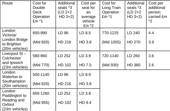
Route Cost for
Double Deck Operation £m *1 Additional seats *3 (LD 2+2 HD 3+2) Cost per seat for an average vehicle £m *2 Cost for Long Train Operation £m *1 Additional seats *3 (LD 2+2 HD 3+2) Cost per additional person carried £m *2 London Victoria/ London Bridge to Brighton (20m vehicles) 650-990 (Mid 820) LD 96 HD 216 LD 8.5 HD 3.8 770-1225 (Mid 1055) LD 240 HD 270 4.4 3.9 Liverpool St – Colchester and Ipswich (23m vehicles) 580-960 (Mid 770) LD 252 HD 102 LD 3.9 HD 7.5 720-1140 (Mid 930) LD 260 HD 360 3.6 2.6 London Waterloo to Southampton (20m vehicles) 500-1140 (Mid 820) LD 96 HD 216 LD 8.9 HD 3.8 London Paddington to Reading and Oxford (23m vehicles) 650-1260 (Mid 955) LD 252 HD 102 LD 3.8 HD 9.4 *1 Comparison costs with disruption included as an overlay
*2 Person carried assessment is used for ranking only (i.e. takes no account of service). The ratio is the additional seats and the mid point in the range of costs.
*3 The increased seat number is based on Double Deck 12 car operation (2*6car) compared to conventional 12 car operation.
Table 1.1 Summary of costs for Double Deck and Long Train Operation
1.1 Summary of Findings for ‘UK Double Deck Vehicle’
The ‘UK Double Deck Vehicle’ was derived by considering vehicles from mainland Europe, making key assumptions about the extent of changes which would be
‘affordable’ to our infrastructure and developing a credible outline vehicle and seating plan. This vehicle was then used to establish, to a greater level of detail, the work required to make the routes available for Double Deck operation.
The vehicles used in the review fell into two overall categories, those built to suit the UIC ‘GB’ Reference Profile at 4320mm above rail level (French Railways gauge) and the UIC ‘GC’ Reference Profile at 4650mm (German and Central European gauge). For UK a body height of around 3800mm is typical. The body width of modern European
nominal 26 metre length double deck vehicles at 2800mm is very similar to that of recent UK rolling stock with a body length of 20.25 metres and would allow a similar seating layout with either a high-density (3+2) or low-density (2+2) format. However, the European bogie pivot point dimension of 20m or more is far more favourable to an efficient seating layout than the 14.17m used on British 20m stock.
In establishing a credible ‘UK’ gauge the limiting factor on height was the assessment of the headroom available for passengers in each floor of the carriage. To derive this consideration was given to other, comparable, transport modes and a height of around 1920mm chosen. This is similar to the smaller London Underground tube stock (e.g. the Victoria Line) but more generous than the typical top deck of a bus. To minimise the overall height low floors are proposed which severely restrict the space for ancillary and traction equipment on the vehicles. For the vehicle width, this was bound by the existing platform dimensions on grounds of both cost and operational flexibility. For the bogie pivot points the distance was held at 14.17m for 20m stock and 16m for 23m stock. This effectively deemed that wholesale repositioning of both curves and curved platforms (e.g. a possible rebuilding Clapham Jcn) unaffordable. The resulting body width was between 2800mm for a 20.25m vehicle and 2740mm for a 23m. This gave a lower seating layout of either a high density 2+2 or an acceptable spacing but low capacity 1+2.
The conclusion of this analysis, combined with the overall structure of the analysis vehicles, effectively confirmed that a vehicle fitting within the existing overall static height of 3990mm would not provide acceptable headroom. This conclusion also addresses the objective to improve the passenger experience and provide for a population that is taller than it has been historically and forecast to have an increasing body mass index.
The adoption of an existing European profile train is considered uneconomic because of the extensive infrastructure work required to accommodate the longer bogie centres with the resulting implications for end throw and mid throw. Work would also be required to the platforms to suit their highly efficient end vestibule arrangements and hence release width for the lower deck. These alterations would be further complicated by the need to continue to support the use of the existing rolling stock. One feature, seen in some European stock, that would be beneficial is the through connection at the high level, but was not assessed in this report.
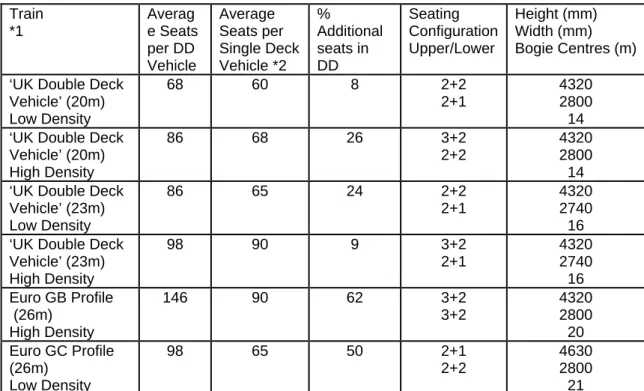
Train *1 Averag e Seats per DD Vehicle Average Seats per Single Deck Vehicle *2 % Additional seats in DD Seating Configuration Upper/Lower Height (mm) Width (mm) Bogie Centres (m) ‘UK Double Deck
Vehicle’ (20m) Low Density 68 60 8 2+2 2+1 4320 2800 14 ‘UK Double Deck
Vehicle’ (20m) High Density 86 68 26 3+2 2+2 4320 2800 14 ‘UK Double Deck
Vehicle’ (23m) Low Density 86 65 24 2+2 2+1 4320 2740 16 ‘UK Double Deck
Vehicle’ (23m) High Density 98 90 9 3+2 2+1 4320 2740 16 Euro GB Profile (26m) High Density 146 90 62 3+2 3+2 4320 2800 20 Euro GC Profile (26m) Low Density 98 65 50 2+1 2+2 4630 2800 21 *1 Train formations for UK vehicles are average vehicle capacity for 6 car sets
*2 Base train is an average vehicle capacity based on a 4 car set
Table 1.2 Capacity and sizing summary of European and ‘UK proposed’ Double Deck Vehicles 8 of 89
Hence a UK profile Double Deck train could provide a 26% additional capacity compared to an equivalent single deck train for a high density (3+2) seating layout or 8% for a low density (2+2) layout based on a nominal 20metre vehicle length. The train size is considered to be practical but has not been fully assessed against all the space requirements for ancillary services and DDA provision which could reduce seating provision. Equally by using the French National Railways (SNCF) 4-car EMU as a reference vehicle some of the generous provision for above deck provision of power equipment (due to the low floor height) could be improved upon to generate more seating space.
1.2 Summary of Routes Assessed for Double Deck
The impact of proposed ‘UK Double Deck vehicle’ on the routes has been assessed by using existing data sources for gauging and route configuration. Where work has been identified then it has been sized into a range of tasks and valued in terms of works costs and disruption impact. Again these criteria values have been allocated on a banded basis rather than individual detail assessment. In assessing disruption reference has been made to other recent major programmes and also the view that there is a ‘credible’ limit to the amount of disruption tolerable on a route e.g. a 6 month closure for a tunnel widening on the Brighton Main line would not be tolerable. Also there are some works for which no credible possession regime / work method could be readily proposed e.g. the raising of the GE overhead line system to ‘GC’ clearance throughout. Where these were identified then an alternative option was followed for the purposes of this report. The assessments demonstrated a mixture of common themes and route specific issues. The nature and conclusions to the main items are discussed below:-
• On those routes with DC Electrification – London Brighton and London
Southampton significant alterations to existing over line structures built prior to the 1960’s and/or lowering of the track formation is required. A substantial lowering of the track level in tunnels would be needed or the construction of a new single track tunnel allowing the existing tunnel to operate as a single line repositioned towards the centre of the tunnel bore.
• For those routes with Overhead Electrification London Ipswich and London Reading: -
o For UIC ‘GB’ vehicles, the raising of the majority of existing over line structures and localised modification to the OLE system over a length of around 500 metres in the vicinity of each structure
o For UIC ‘GC’ vehicles, the raising of the majority of existing over line structures and the modification of the entire overhead line electrification system to achieve the required electrical safety clearance.
• The CTRL main line has been constructed to the mandated UIC ‘GC’
Reference Profile size and the larger 4650mm vehicle height could be operated on this route. Separate platforms have been provided at European platform gauge for international services and UK platform gauge for domestic services. • In reviewing the bridge, canopy and other overhanging structures the majority
(in volume) can be addressed at reasonable cost and possession length. However, there is a number of what could be deemed exceptional structures which have a disproportionate cost. Examples of these include overlapping and interlaced bridges i.e. rail over rail over road where work will be required on
all three levels, bridges carrying extensive property activities e.g. Croydon and occasional listed structures.
• Depot provision, a sum has been allowed for the construction of new facilities at the depots to accommodate the taller trains and some infrastructure amendments.
Route Work
Types A-E £m
Major Items (e.g. tunnels, major structures, rewiring) £m Works Total £m Disruption Allowance (30%of mid) £m Total £m London Victoria/ London Bridge to Brighton GB 105-170 350-530 460-800 190 650-990 London Victoria/ London Bridge to Brighton GC 190-290 390-690 580-980 230 810-1200 Liverpool St – Colchester and Ipswich GB 200-390 200-295 400-785 180 580-960 Liverpool St – Colchester and Ipswich London GC 310-520 320-560 630-1080 260 890-1340 Waterloo to Southampton GB 90-350 85-340 310-950 190 500-1140 Waterloo to Southampton GC 130-530 100-410 375-1200 235 610-1440 London Paddington to Reading and Oxford GB 90-350 340-690 430-1040 220 650-1260 London Paddington to Reading and Oxford GC 140-570 370-860 510-1430 290 800-1720 Table 1.3 Summary of infrastructure work activity and comparison costs for the introduction of Double Deck vehicles.
1.3 Summary of Assessment of Long Train Operation and works
The impact of operating longer trains on the routes has been assessed by using existing data sources for platform lengths, gauging and route configuration. Where work has been identified then it has been sized into a range of tasks and valued in terms of works costs and disruption impact. Again these criteria values have been allocated on a banded basis rather than individual detail assessment. The work required is more varied than for the Double Deck operation and is more associated with junction and station layouts. These works tend to attract higher costs than the civil engineering activity required for increase route clearance. There is however opportunity to integrate the works with other maintenance and renewal activity over time to reduce the overall disruption on the route. In undertaking the analysis it was noted that issues of
passenger loading and junction occupancy would be significant issues not being addressed in this study. Any future study would need to address the management of people flow and the facilities at stations to achieve balanced loadings of the train and adequate dwell times. A review of junction occupancy will also be required to confirm
that the longer trains do not have a severe impact on the overall capacity of the network. The assessments demonstrated a mixture of common themes and route specific issues. The nature and conclusions to the main items are discussed below:-
• The overall assumption is that the vehicles will be within the existing rolling stock clearances.
• Work to extend platforms can be straightforward and this is reflected at some locations. However, some will affect the associated junctions, signalling and will require land take. In some cases the land may not be available in and restricted or reduced facilities (junction size) would be the only option.
• For effective dispersal at the terminal stations and for passenger loading at the feeder stations a considerable amount of flow management equipment will be required and this is not allowed for in this work.
• Depot provision has not been reviewed in depth. However, it is expected that lengthening is likely to be more expensive than the Double Deck option. Examples of work required include, additional land to accommodate the longer train lengths, depot connections would need to be moved and the provision of carriage sidings on the network would need confirming.
• The work showed that there could be optimal solutions between 12 and 16 vehicle formations which will require further work to confirm.
Route Associated
works £m
Major Items (e.g. major re-modelling) £m Works Total £m Disruption Allowance £m Total £m London Victoria/ London Bridge to Brighton 260-560 280-435 540-995 230 (30% of 780) 770-1225 Liverpool St – Colchester and Ipswich 240-360 260-560 500-920 220 (30% of 710) 720-1140 Table 1.4 Summary of infrastructure work activity and comparison costs for the introduction of Long Trains.
1.4 Supporting Issues and Comment
As part of the study, consideration was given to the background of available gauges to both the UK and Continental railways. Whilst not directly used in the evaluation this does give a background understanding as to why the application of Double Deck
vehicles is more economical on some railway networks than others. It also validates the conclusion that many of the findings are transferable between UK routes.
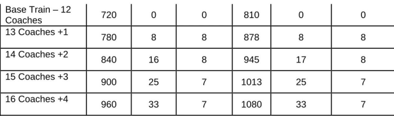
The capacity of longer trains was established by using a 4 car ‘Electrostar’ set as a base vehicle and extension with typical standard class vehicles.
Train Total Seats LD % Seats on base % Seats on increment Total Seats HD % Seats on base % Seats on increment 11 of 89
Base Train – 12 Coaches 720 0 0 810 0 0 13 Coaches +1 780 8 8 878 8 8 14 Coaches +2 840 16 8 945 17 8 15 Coaches +3 900 25 7 1013 25 7 16 Coaches +4 960 33 7 1080 33 7
Table 1.5 Capacity summary for ‘Long Trains’ (above 12 coaches)
2 P
URPOSEContinued growth in demand on the core commuter routes into London could see a doubling in passenger numbers over the next 30 years. This level of increase will be met in the early phases by solutions which are well understood and applied through the Route Utilisation Process (RUS). This approach is expected to meet demand until around 2020. The purpose of this study is to explore the implications of the application of Double Deck vehicles or Extra Long trains to address the continued growth. These two options are amongst a number of possible solutions which include additional trains through improved performance, use of ERTMS to increase route capacity, the use of different rolling stock ‘layouts’ and the possible construction of additional routes.
This study has completed a structured assessment of the opportunities and implications of operating a Double Deck train or Long Trains on a selection of inter-urban routes around London. To achieve this end the following criteria for this element were established:-
• A concept design for a double deck vehicle to address: - passenger capacity, DDA compliance, on train systems and the overall height / length of the vehicles.
• Measure of the additional capacity provided and a comparison with capacity provided by longer trains and double deck trains.
• Implications for station design and station dwell times.
• An infrastructure assessment which uses existing ‘Omnicom’ video surveys, ClearRoute and other existing data sources to establish the extent of clearance works.
• A broad scoping and costing of the identified works based on unit rates and generic solutions to implement
o Double Deck Trains
o Very Long (16 car x 20m or equivalent)
The assessments also addressed the relative incremental cost of achieving UIC GB or GB+ and GC vehicle height concurrent with any works (including any additional scope items).
The routes for Double Deck evaluation are (rationale for each is noted):
• London Victoria/ London Bridge to Brighton (Third Rail, Commuter mainline with tunnels operating at near capacity)
• Liverpool St – Colchester initially then onto Ipswich (OHLE commuter line operating at near capacity)
• Paddington to Reading then onto Oxford and Bristol (OHLE and Diesel operation but built to wider track initially)
• London Waterloo to Southampton (Third Rail, Commuter mainline with tunnels)
Outline statements will also be prepared for • CTRL – London St Pancras to Ashford
For the extra long train evaluation only the first two routes will be used and a current standard stopping pattern assumed for the stations.
• London Victoria/London Bridge to Brighton
Station Stops – Clapham Junction, East Croydon (via both Quarry Line and the Redhill Line) Redhill, Gatwick Airport, Three Bridges and Haywards Heath Liverpool St – Colchester and Ipswich
Station Stops – Stratford, Romford, Shenfield, Chelmsford, Witham, Marks Tey, Colchester and Manningtree
3 M
ETHODOLOGYTo undertake this concept study in to the alternatives of using Double Deck vehicles or longer trains (12-16 coaches) the first phase established the possible vehicle
configurations and then applied these to the selected routes. The route configurations and capabilities were taken from existing sources and the scope and complexity of the work was derived form these records. The cost of works, were established from a range of current projects and allowances made for the expected additional items such as access, contingency and legal permissions (e.g. TWA).
In deriving the ‘UK Double Deck vehicle’ the trade off between vehicle size and the work required to achieve clearance evidence was developed in a series of iterations, firstly by assessing the historic ruling design criteria for the route. These overall findings gave a robust basis to assess between a marginal improvement in capability and a major rebuild of a route. Secondly these assumptions were tested for items which significantly constrained the capacity of the vehicle to confirm the volume of work on the route. Examples of the overarching constraints included curving rules and bogie spacing which impact on the end and mid throw of the vehicle and the height of platforms which
constrain both access to and width of a lower passenger deck.
Evaluation of the works was undertaken on a generic basis of typical work scopes rather than site specific detail. This principle was then carried through into the costing process by giving a standard rate to similar work activities. For the larger and more complex items e.g. tunnels and major junction alterations some site specific detail was added in to confirm the validity of the concept design. For some of the works consideration was given to the incremental costs of achieving other outputs. For example the relative incremental cost of achieving UIC GB+ concurrent with any works. The evaluation of work excluded a number of items at this stage, principally timetable analysis and the impact on traction power. The study also did not address issues of station crowding and dispersal issues. Generic assumptions were made for changes to depots and stabling facilities.
3.1 Characteristics
of Double Deck Vehicle
This study uses the experience of the use of double deck trains with other operators to establish a credible vehicle outline and occupancy for UK use. In assessing these existing vehicles the following assumptions were used -
• The service pattern will be for outer suburban operations where the station stops are generally infrequent (compared to inner suburban operations) but with sufficient consideration of stations where peaks of loading occur.
• The general layout and seating density will be comparable with existing outer suburban vehicles although it is anticipated the roof height will be constrained. • The vehicle will be designed to fit with current platform designs as these trains will need to operate alongside existing rolling stock which will also operate on these routes.
• The issues of flow of people on and off the Platforms will be dealt with by a future assessment. (Consideration will be given to the time required for the reasonable access and egress by the vehicle concept design).
• Vehicle length is not expected to exceed 23m (noted that European vehicles are 26m compared with a historical design limit of 20m stock for the southern
routes).
3.2 Concept Design for UK Double Deck Vehicles
This study has reviewed the leading dimensions: vehicle body length; vehicle height, vehicle width and seating layout of double deck rolling stock currently operating in mainland Europe.
The leading dimensions of European mainland rolling stock are normally defined by vehicle gauges established by the UIC and commonly known as the UIC ‘GB’ and ‘GC’ Reference Profiles and these are summarised in table 3.1. It has been established that the maximum vehicle body width of current mainland Europe double deck stock is in the order of 2800mm for a standard 26.4m length vehicle and that this width is very similar to that of current UK passenger vehicles.
These typical European dimensions compare with the cross section dimensions of passenger vehicles operating in the UK which are in the range 2700mm to 2820mm in width and at a height of around 3800mm.
Height (static) (mm) Width (static) (mm) Height (kin) (mm) Width (kin) (mm) Vehicle Width (mm) Length (m) UIC GB 4320 3150 4350 3290 2800 26.4 UIC GC 4650 3150 4700 3290 2800 26.4 GB Typicals 3990 2820 4015 3020 2700-2820 23.0
Table 3.1 Summary of European and UK leading dimensions
The study uses these overall dimensions, the bogie positions and their associated seating capacities to assess the impact of applying similar vehicle parameters to the UK routes. The subsequent trades between vehicle size and route clearance works
undertaken on the basis of the costs of the works and/or the loss of capacity in the vehicle.
The concept design takes account of the need to accommodate the current UK platform gauge and this has the effect of reducing the external body width of the lower saloon between the vehicle bogies.
To inform the assessment of the potential seating capacity comparison is made with the layout of a modern French National Railways (SNCF) 4-car EMU. Initial analysis has been carried out for a second class vehicle with the maximum possible seating capacity and the figures compared with a range of current UK vehicles of nominal 23 metre and 20 metre body length also with all standard class seating and comparable loss of seating area due to standard toilet compartments. The resulting percentage increases
in seating capacity can be regarded as maxima for the trailer vehicle. This reference vehicle also featured a low floor height which is a necessary feature of the UK vehicle. To achieve this there is a generous allowance for above floor equipment in the end vehicles. For the purposes of this study these have been reflected in the proposed train and a opportunity recorded for improving the arrangements for the traction equipment. The estimation of the potential seating capacity of a UK profile double deck vehicle for nominal 23 metre and 20 metre body lengths is thereby determined for both high density (3+2) and low density (2+2) seating layouts in the upper saloon and for a similar seat bay length to current UK practice.
To extrapolate the seating capacity of a single vehicle to that of a train allowances were made for a reduced density of seating in first class accommodation, wheelchair space, provision for disabled toilet facilities and space provision for electrical and auxiliary equipment that would primarily be mounted below saloon floor level in conventional EMU stock. Figures have been assessed based on a comparison of the relative seating capacities of the all-second class vehicle with that of the Driving Coach and composite coach of the French Railways EMU ‘analysis’ vehicles. The provision for standing passengers was derived from the current standards on vehicle loading and the franchise targets for an acceptable level of standing on a day to day basis.
Appendix K of this report examines the background to the development of mainland Europe vehicle gauges, describes the UIC ‘GB’ and ‘GC’ Reference Profiles and relates the reference profiles to actual vehicle body lengths and widths that are in current operation.
3.3 Extra Long Train Operation
The evaluation of extra long trains focused on the testing of the physical fit of 16 car trains on the routes. Where, it is accepted that an incremental approach would demonstrate the marginal benefits of each stage but this will be a refinement of the study. The assumptions and start points used for the longer trains are -
• The additional vehicles will fit to the existing infrastructure in terms of gauge, speed, acceleration, braking and compatibility with existing rolling stock. • Issues of station design and station dwell times will be covered by a future
investigation.
• Issues of junction occupancy and clearance times will be addressed by a future timetable study.
The passenger capacity of extra long trains has been determined based on 16 car x nominal 20 metre vehicle formations requiring an extension of existing 12 car platforms by around 85 metres.
An assessment of the requirements for provision of extended platforms has been made for the terminal and principal stopping points on the selected routes to determine physical space and the extent of changes to track layout and signalling. Order of magnitude costing for physical works have been determined for the assessed changes to infrastructure.
3.4 Evaluation of Work Scope
Evaluation of the works was undertaken on a generic basis of blocks of scope rather than site specific detail. Need for the work was derived from a number of existing sources and an analysis of current and historical standards. Where appropriate the opportunity to achieve further capability improvement at marginal cost was explored e.g. the incremental cost of achieving UIC GB+.
The evaluation of work excluded a number of items at this stage, principally timetable analysis and the impact on traction power. The study also did not address issues of station crowding and dispersal issues. Generic assumptions were made for changes to depots and stabling facilities.
To establish current route capability the following resources were used -
• ‘Omnicom’ route video to identify all over line structures and other railway infrastructure that could be foul of rolling stock of greater height than for current operations Omnicom’ video surveys.
• The Network Rail National Gauging Database has been used to obtain the current height from rail level to underside of the bridge and profile of the deck or arch.
• Ordnance Survey mapping has been used to assess the surrounding area at each over line structure to identify urban, residential and rural conditions. Based on the UIC ‘GB’ or ‘GC’ Reference Profile height of 4350mm and 4700mm above rail level respectively plus an allowance of 200mm for gauge clearance, any requirement for raising of the bridge deck, reconstruction of the bridge deck or the potential for track lowering has been identified.
The complexity of any work to raise the height of the bridge and the consequential effect on the surrounding area at road level together with the likelihood of there being
significant gas, water, drainage, power and telecommunications routes at road level has been assessed.
The study considers the incremental cost of enhancing the loading gauge to support UIC GB+ and UIC GC operation so as to understand the incremental costs of going to a further enlarged gauge (with implications for passenger acceptability).
For all activities an assessment of the likely disruption to services (in terms of physical extent and duration) has been made.
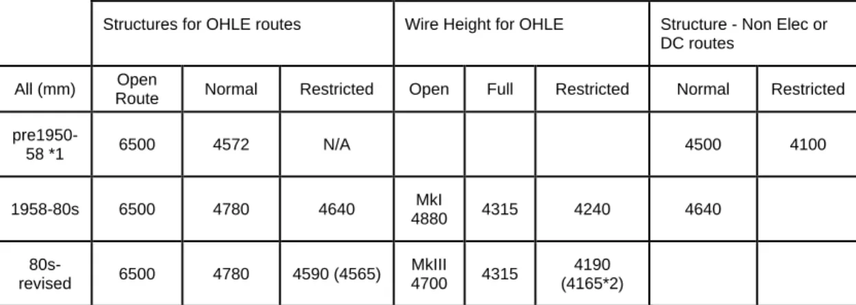
To confirm assumptions and generic scope two pieces of background work are included firstly, Appendix M describes the development of vehicle and structure gauges in the UK and the dimensional relationship between Overhead Line electrification equipment and over line structures in order to identify expectations for the extent of infrastructure works. Secondly Appendix J describes the dimensional relationship of overhead line equipment to over line structures.
3.5 Costing of Work
Potential works have been allocated against a five point scale to reflect the complexity of the works and disruption to railway business and the local area with a broad order of
cost determined for each category. This will give an approximate cost for the introduction of a double deck train on each route, along with a commentary on key issues to be addressed, scale and timings for any disruptions.
In drawing together a total number allowances have been added for depot works and other significant infrastructure items. Then an overall project management percentage has been used. In this case 15% was selected in recognition of the overall complexity of either solution. A broad contingency of -50 / +100% is applied to reflect the range of possible scope solutions. An allowance for disruption is then applied to the range in recognition of how the evaluation and treatment of disruption can vary over time. In assessing disruption an overall figure of 30% was used for most works. Where specific and extensive disruption would occur (e.g. protracted route closure) then additional lump sums were included (circa £10m per item) by revising the percentage.
4 F
INDINGS–
C
ONCEPTD
ESIGN FORD
OUBLED
ECKV
EHICLES4.1 Key features of European mainland double deck rolling stock
Around thirteen examples of European Double Deck rolling stock were compared to understand the trends in development and the variations in application and the specific gauge characteristics of the host nation.
The discussion and base information used is located in –
• Appendix K which examines the background to the development of mainland Europe vehicle gauges, describes the UIC ‘GB’ and ‘GC’ Reference Profiles and relates the reference profiles to actual vehicle body lengths and widths that are in current operation.
• Appendix C examines the detailed sizing of mainland European rolling stock to allow comparison with the UK vehicle gauge width.
• Appendix L describes the application, to date, of the UIC Reference profiles in the UK
The conclusions of this review are summarised below –
• Double deck rolling stock operated by the principal European mainland railways on conventional rather than high speed routes are based on three principal vehicle layouts
o Intermediate trailer vehicles with two sets of 1800mm wide doorways per side positioned over the bogies and serving a vestibule area with the floor level at around 1150mm above rail level.
o Driving trailer vehicles or EMU driving coaches with two sets of 1800mm wide doorways per side positioned inboard of the bogies and serving a vestibule area with a floor level at around 600mm above rail level. o French Railways EMU vehicles with three sets of doorways per side
serving vestibule areas with a floor level at around 1000mm above rail level optimised for high volume suburban services with limited station dwell time.
o For the intermediate trailer design, stairways run from each vestibule area to the lower saloon requiring 3 or 4 steps and to the upper saloon
requiring 7 steps.
• A short ramp or single step connects the vestibules of the driving coach design to the lower saloon and a 3 or 4 steps link to a small saloon area positioned over the bogies with a further similar flight from the bogie area saloon to the upper saloon.
• To minimise the footprint of the stairways, the riser and going dimensions provide a steeper than average stair design than is normally applied to areas with public access.
• Allowing for the inter vehicle gangway, the vestibule area has sufficient space for a standard toilet compartment or a group of facing seating on each side of the
gangway. Provision for a larger disabled toilet compartment requires a reduction of the seating saloon areas and is usually placed in the driving vehicle.
For comparison, Appendix B shows the layout of German National Railways intermediate coach and driving trailer vehicles with a lower density seating layout.
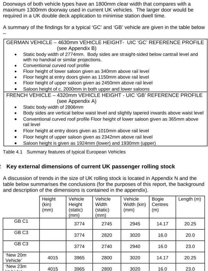
Doorways of both vehicle types have an 1800mm clear width that compares with a maximum 1300mm doorway used in current UK vehicles. The larger door would be required in a UK double deck application to minimise station dwell time.
A summary of the findings for a typical ‘GC’ and ‘GB’ vehicle are given in the table below –
GERMAN VEHICLE – 4630mm VEHICLE HEIGHT- UIC ‘GC’ REFERENCE PROFILE
(see Appendix B)
• Static body width of 2774mm. Body sides are straight-sided below cantrail level and with no handrail or similar projections.
• Conventional curved roof profile
• Floor height of lower saloon given as 340mm above rail level • Floor height at entry doors given as 1150mm above rail level • Floor height of upper saloon given as 2450mm above rail level
• Saloon height of c. 2000mm in both upper and lower saloons
FRENCH VEHICLE – 4320mm VEHICLE HEIGHT - UIC ‘GB’ REFERENCE PROFILE
(see Appendix A)
• Static body width of 2806mm
• Body sides are vertical below waist level and slightly tapered inwards above waist level
• Conventional curved roof profile Floor height of lower saloon given as 365mm above rail level
• Floor height at entry doors given as 1010mm above rail level
• Floor height of upper saloon given as 2342mm above rail level
• Saloon height is given as 1924mm (lower) and 1930mm (upper) Table 4.1 Summary features of typical European Vehicles
4.2 Key external dimensions of current UK passenger rolling stock
A discussion of trends in the size of UK rolling stock is located in Appendix N and the table below summarises the conclusions (for the purposes of this report, the background and description of the dimensions is contained in the appendix).
Height (kin) (mm) Vehicle Height (static) (mm) Vehicle Width (static) (mm) Vehicle Width (kin) (mm) Bogie Centres (m) Length (m) GB C1 3774 2745 2945 14.17 20.25 GB C3 3774 2820 3020 16.0 20.0 GB C3 3774 2740 2940 16.0 23.0 ‘New 20m Vehicle’ 4015 3965 2800 3020 14.17 20.25 ‘New 23m Vehicle’ 4015 3965 2800 3020 16.0 23.0
Table 4.2 Summary of UK vehicle dimensions
The two ‘new vehicle’ dimensions were therefore used as a basis for developing the shell of the ‘UK Double Deck Vehicle’. Whilst height is the obvious constraint the loss of vehicle length and the relatively tight bogie centres, compared to the European vehicles cause significant constraints on the capacity of a double deck vehicle. Consideration was given to extending the length of the vehicles and whilst this would generate some advantage this is limited by the constraint on the lower deck from the bogie positions. Also increasing length on some of the southern suburban routes would lead to extensive infrastructure changes given the ruling ‘20m’ design of the infrastructure. Similar
consideration was given to moving the bogie centres, but this again would lead to a wholesale reconfiguration of the railway especially on the tighter curves and through features such as stations on curves. For example the wholesale alignment and re-construction of Clapham Junction. The study also showed that for some of the southern routes longer vehicles could be deployed in which case benefits similar to the 23m vehicle could be gained. This study did not seek to confirm this for any particular route but the London – Brighton is considered the most likely and the South Eastern the more restrictive.
4.3 Key internal dimensions and layout of current UK passenger rolling stock
The layout of current inter-urban rolling stock in the UK has the following characteristics: • Double sliding or plug door openings at approximately one-third and two-third
positions over the body length.
• Maximum 1300mm clear door openings.
• Vehicle floor height of around 1150mm above rail level.
• The length of facing seating bays vary between 1770mm and 1830mm for standard seating plus an additional 100mm for designated priority seating. • Pitch length for airline layout seating varies between 760mm and 830mm for
standard seating plus an additional 100mm for designated priority seating. • Internal saloon width of 2650mm for the typical 2800mm maximum external
body width as identified above.
• Standard Class seating is arranged in a ‘low density’ (2+2) format with armrests or ‘high density’ (3+2) format without armrests and in some cases with a
combination of both types within a train set.
• First Class seating is arranged in either a (2+2) or (2+1) format always with armrests.
• Individual seats HD min 455mm no armrests, LD same with 60mm armrests. For the purposes of this study the layout of the ‘Electrostar’ stock will be used as a base for comparison and population of the vehicle shell.
Density Seat width (mm) Gangway (mm) Interior Saloon width (mm) Spacing (mm) Comments Low (2+2) 1090 470 2650 1770 Face 775 Air Armrests High (3+2) 1370 (3) 910 (2) 370 2650 1770 Face 775 Air No armrests. Min. gangway for trolley service High (3+2) 1390 (3) 925(2) 335 2650 1770 Face 775 Air No armrests
No access for trolley Table 4.3 Summary of seating layouts used for the UK DD vehicle (derived from Electrostar).
4.4 Provision for standing passengers in current UK rolling stock
To provide a valid comparison of total vehicle and train capacity between conventional UK rolling stock and a proposed UK profile double deck train an estimate of standing capacity is required.
Railway Group Standard GM/RT 2100 ‘Structural Requirements for Railway Vehicles’ provides some direction on this matter in the section of the standard covering vertical loading.
The payload for passenger vehicles should be within:
• a minimum loading of 80kg x (number of seats in the vehicle) plus (4 x the floor area in square metres of passageways and vestibules)
• a maximum loading of 71.5kg x (number of seats in the vehicle) plus (8.6 x the floor area in square metres of passageways and vestibules)
The floor areas of vestibules and longitudinal gangways (but excluding the space
between facing seats have been assessed for the interior trailer vehicle of three types of modern suburban layout interior trailer coaches with maximum seating capacity and no toilet facilities.
The table below shows the floor areas, standing capacity figures for the lower density 80kg (12.6 stone) per person and higher density 71.5kg (11.3 stone) per person assessments and associated crowd loading and crush loading vehicle capacities. For comparison the density of persons per square metre for the crowd loading of 5KN/m² used in the design of bridges and public buildings is just over 7 compared to 4 for rail vehicle crowd loading and 8.6 for crush loading respectively.
Vehicle
Seating
Capacity Floor Area
Crowd at 4 per m² % of Seating Crush at 8.6 per m² % of Seating Class 165 DMU 106 19.1 m² 76 71% 164 155% Class 465 EMU 90 16.8 m² 67 74% 144 160% Class 375 EMU 68 17.5 m² 70 106% 150 220% 23 of 89
Table 4.4 Evaluation of crowding capacity in current rolling stock.
Based on these sample results it is proposed that an average standing capacity of 75% of the seated capacity is adopted in overall train capacity determinations within this report.
This analysis provides the comparison figure for a technical crowded level carrying capacity. In terms of service provision it is expected that the current commercial targets of no standing for journeys over 20minutes and no more than around 30% standing for shorter journeys are likely to apply.
4.5 Concept Design for UK Profile Double Deck Vehicle
The analysis of European and UK practice has been drawn to together to produce the concept design for a UK profile vehicle and then extrapolated into a train formation. In drawing the analyses together the following have been addressed and are discussed in the following sections:
• Acceptable height of each saloon • Achievable width of each saloon • Seating capability of each saloon
• Seating layout of each saloon for each vehicle length • Reprise of the arguments for a 26m vehicle
• Reprise of the arguments for using a ‘standard European vehicle
The concept design study for a UK profile double deck vehicle has examined passenger vehicle lengths in current use in the UK and, as concluded in section 4.2, will use the following dimensions for the overall shell –
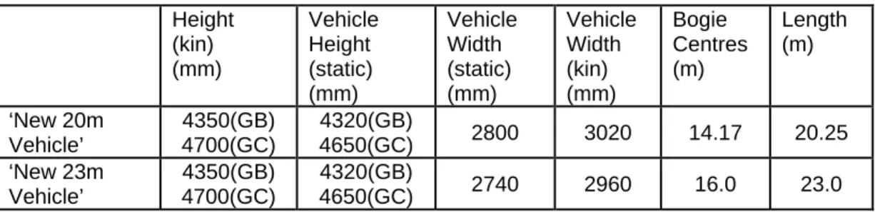
Height (kin) (mm) Vehicle Height (static) (mm) Vehicle Width (static) (mm) Vehicle Width (kin) (mm) Bogie Centres (m) Length (m) ‘New 20m Vehicle’ 4350(GB) 4700(GC) 4320(GB) 4650(GC) 2800 3020 14.17 20.25 ‘New 23m Vehicle’ 4350(GB) 4700(GC) 4320(GB) 4650(GC) 2740 2960 16.0 23.0
Table 4.5 Assumed vehicle dimensions for Double Deck vehicle (see appendix D) Height of Vehicle
To derive an acceptable saloon height comparison was made between heights achieved in the two European vehicles namely 2000mm, 1924mm and 1930mm and those
experienced on other transport modes as a qualitative measure. From this a minimum value of 1920mm was chosen, this is similar to the London Underground tube stock (e.g. the Victoria Line) but taller than the top deck of a double deck bus. This
assessment also aligns with the overall objective of providing an improved passenger environment by providing for a population that is taller than it has been historically and
forecast to have an increasing body mass index. From the 1920mm cabin provision a vehicle size of 4320mm was derived which then gave a vehicle requiring GB clearance as a minimum. For the purposes of the study a GC vehicle was evaluated to
understand the cost premium of providing further improvement in height and the possible benefit of a improved gauge for freight use. This gave a vehicle height of 4650mm and a cabin height of 2030mm. (If a GC vehicle was fully engineered then it is expected that the cabin heights would reduce to provide more under-floor space for equipment etc.) Appendix D shows the derivation and allowances in establishing the heights and an indicative cross section of the vehicle.
Width of Lower Passenger Saloon
The potential width of the lower passenger saloon has been assessed from
consideration of the ‘lower sector’ structure gauge that is applicable up to 1100mm above rail level and is defined in Railway Group Standard GC/RT 5212. Adherence to an acceptable limit on width is necessary to avoid ‘low’ structures such as bridge beams and shunt signals.
Conventional passenger vehicles have operational equipment mounted beneath the coach body having a typical maximum width of around 2180mm for exposed equipment. For those with enclosed equipment the maximum width just beneath the underside of the vehicle body is around 2300mm with an angled profile reducing to 1920mm at the bottom corner at 250mm above rail level.
Records show that a two level car transporting van with a rectangular cross section lower deck area between bogies at 13.25m centres had an external body width of 2275mm.
The ‘upper sector’ body width for 23m vehicles is 80mm less than the body width for a vehicle with full C3 profile of 2820mm and this reduction can be deemed to also apply to the lower sector area.
Research into the derivation of the lower sector gauge width suggests that there is some degree of conservatism in the assessment of the controlling dimensions and that a detailed gauging study applying minimum clearances may permit an increased saloon width.
Based on the above a maximum external width of a lower saloon is assessed as 2300mm for a nominal 20 metre vehicle length and 2250mm for a 23 metre vehicle Layout of Lower Passenger Saloon
For an external width body of 2300mm and allowing 75mm for thickness of body
construction, the interior saloon width would be 2150mm. This compares with 2650mm in the Electrostar vehicle. A range of seating options was considered and summarised in table 4.6.
For the lower saloon in the 20m vehicle the 2+2 formation (B) is acceptable with a minimum gangway provision of 330mm (compared to 335mm in the most compact Electrostar layout),
The assessment of the lower saloon width for a 23m vehicle is 50mm narrower than for 20m vehicles. Applied directly, as shown in the table, this makes the gangway
unacceptable. However, a potential seating option for a HD seating with an additional 6 seats could be used. This contrasts with a full 2+2 seating layout which would give 14
seats and is assumed to be achieved by amendments to body construction thickness and individual seat widths. Achievement of this is logged as a opportunity as it may not be possible or acceptable from a passenger comfort viewpoint. To balance this in for the HD option a optimistic 3+2 layout has been used in the upper saloon (see next section).
Option Length (m) Density Seat width (mm) Electrosta r Gangway *1 (mm) UK DD Lower Gangway (mm) UK DD Lower width (mm) A 20 Low (2+1) 1090 (2) 575 (1) 985 485 2150 B 20 High (2+2) 910 (2) 830 330 2150 C 23 Low (2+1) 1090 (2) 575 (1) 985 435 2100 D*2 23 High (2+2) 910 (2) 470 280 2100
Table 4.6 Summary of lower seating layout options used for the UK DD vehicle. *1 Included for comparison purposes – proposed DD seats in an Electrostar
*2 Provisional option, not used – depends on detail design to achieve an acceptable gangway. For typical EMU stock the bottom edge of the window is at around 800mm above floor level. For a typical lower saloon floor level of around 370mm above rail level, the bottom of the window would be positioned at a height of 370mm + 800mm giving 1170mm and this would place a window fully within the vehicle gauge ‘upper sector’ thereby simplifying the detailing of the transition between lower sector and upper sector body widths.
In summary options A LD, B HD and C LD&HD in table 4.6 will be used for the typical vehicle.
Width and Layout of Upper Passenger Saloon
The effective body width for the upper saloon was derived from comparison with modern rolling stock with a nominal 20m body length (Class 357, 375 and 377) giving an
external saloon width of 2650mm. This is large enough to accommodate the ‘normal’ Electrostar type layouts in either high or low density configuration.
Option Length (m)
Density Seat width (mm) Electrostar Gangway *1 (mm) UK DD Upper Gangway (mm) UK DD Upper width (mm) A 20 Low (2+2) 1090 (2) 470 470 2650 B 20 High (3+2) 1370 (3) 910 (2) 370 370 2650 C 23 Low (2+2) 1090 (2) 470 420 2590 D 23 High (3+2) 1370 (3) 910 (2) 370 310 2590
Table 4.7 Summary of upper seating layout options used for the UK DD vehicle. *1 Included for comparison purposes – proposed DD seats in an Electrostar
For the 23m vehicle further consideration has to be given to the narrowing of the vehicle required to accommodate the greater length. It is also likely that additional tapering of
the body side will be necessary and the further chamfering of the body ends. In summary it is assumed that the 3+2 high density layout will become constrained. However, this option (D) has been adopted to give a balance to the risks and
opportunities for HD seating arrangements in the longer, but narrower 23m vehicle. In summary the two options A and D will be used to evaluate the typical vehicle whilst noting that a high density configuration could be used for shorter journeys.
Review of nominal 26m length vehicle
The study has also considered a nominal 26 metre length vehicle that is the standard body size for European coaching stock.
The French Railways EMU intermediate trailer vehicle used for analysis of seating capacity has a 26.1m length body and 20.0m bogie centres that maximises the space available in the lower passenger saloon area.
The length of the central passenger saloon area is 15400mm and that of the vehicle end sections incorporating the entrance/exit vestibule, stairways to the passenger saloons, standard toilet, end gangways to adjacent coach and some seating is 5450mm. The Intercity Express Programme (IEP) has examined the gauging of 26m vehicles adapted for operation on current UK infrastructure with a kinematic envelope no greater than that for a current nominal 23m vehicle.
It has been determined that the vehicles would have to be proportioned with 17 metre rather than the normal maximum 20 metre bogie centres used on modern European double deck vehicles to allow for end and centre throw restrictions on curved track imposed by the current infrastructure.
The effect of this would be to reduce the length of the central passenger saloon area from 15400mm to 12400mm with consequential loss of two seating bays per saloon and increase the length of the end sections by 1.5m each with some additional seating provided.
The initial gauging study has also determined that a tapering body profile may be required over a length of around 2 metres at body ends to match the 23m vehicle gauging profile and the consequential narrowing of the saloon width could also require the removal of some seating to retain an adequate gangway width.
The consequential reduction in the length of the lower saloon between the bogies has a significant effect on the potential seating capacity.
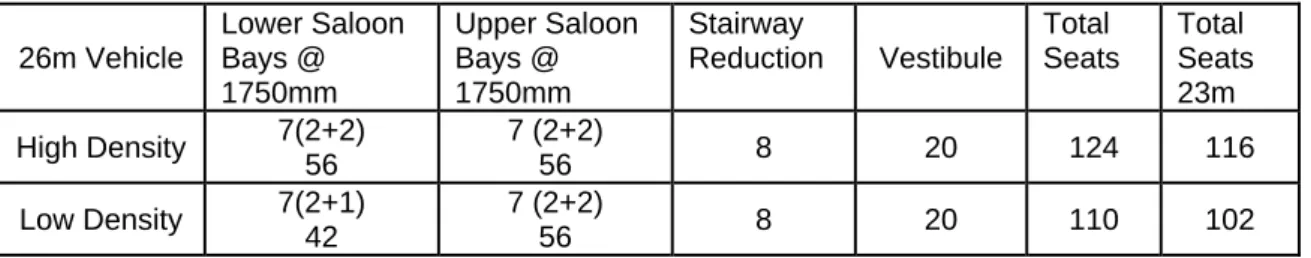
An analysis of the seating capacity for a 26m vehicle layout as described is included below showing a marginal increase in capacity of eight seats over the 23m vehicle. All the additional seating is in the vestibule which is not ideal for the duration of outer suburban trips.
Given this marginal increase in seating, the vestibule location and the significant cost implications for accommodating the longer vehicle the study focused on the 23m option.
26m Vehicle Lower Saloon Bays @ 1750mm Upper Saloon Bays @ 1750mm Stairway Reduction Vestibule Total Seats Total Seats 23m High Density 7(2+2) 56 7 (2+2) 56 8 20 124 116 Low Density 7(2+1) 42 7 (2+2) 56 8 20 110 102
Table 4.8 Comparison of seating capacity between 23m and 26m vehicles
*1 Assume an increase in the length of the end vestibules of 1500mm each allowing two additional rows of airline seating in (2+2) layout per vestibule.
(Note: for a complete description of the vehicle seating calculations see section 5.)
4.6
Potential for use of Standard European Mainland Vehicles
The review has considered the practicalities of operating standard European production 26.4m length double deck vehicles on UK infrastructure. The seating capacity of a standard 26.4m length vehicle with 19m bogie centres and based on a seating bay length layout that is comparable with current UK inter-urban stock would give around a 65% increase in seating capacity. This is achieved with an external body width of 2800mm applies for the full depth of the body profile down to around 350mm above rail level.
To adopt such a vehicle would require the wholesale reconstruction of all the stations to make them compatible with the required UIC reference profile. The new platforms would then be unavailable for use with conventional UK stock as the stepping distance would be significantly in excess of the current maximum UK requirements of 275 horizontal, 250mm vertical and 350mm diagonal between platform edge and vehicle step or floor. (The UK platform gauge is also applied to under bridge girders and some types of signalling equipment that would also be foul of gauge). Work would also be needed to address the side and end throw of the vehicles.
The option to utilise this form of stock was therefore discounted both on grounds of the cost of the works and the resulting lack of flexibility for the network as a whole.
One area where these vehicles could be used is on the CTRL route. Here platform dimensions that are compatible with the UIC ‘GB’ and ‘GC’ reference gauges that have been adopted making a dedicated fleet possible.
5 E
STIMATE OFS
EATINGC
APACITY OFUK
P
ROFILED
OUBLED
ECKV
EHICLES5.1 Base Analysis vehicle
To estimate the potential seating capacity for a UK profile double deck vehicle can be made by comparison with the intermediate Second class trailer of the French Railways Class Z20500 EMU illustrated, along with its leading dimensions in Appendix A. The sizing of the vestibules, saloons and doorways were assessed and proportioned back to the proposed dimensions of the UK vehicles. Allowances were also made for the tighter seat spacing used in the French vehicle (i.e. expanded to a typical spacing for UK application). The estimates were made by varying the seating pitch and layout of the centre saloons whilst retaining the layout of the entrance vestibules and stairways to the passenger saloons. The analysis has been conducted on the standard class layout and the results compared with current UK vehicles of similar format. (With seat bay lengths in the range 1700mm to1800mm determined to ‘fit’ the shorter ‘UK’ saloon lengths).
5.2 Analysis of the 23m vehicle
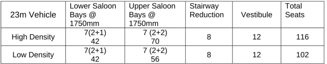
For a nominal 23m vehicle with 16m bogie centres by reduction of the central saloon length of the analysis vehicle by the difference in bogie centres of 4000mm giving an 11400mm saloon. Bay length of 6 would be too short and 7 too long. So with an assumed vestibule end reduction of 425mm this gives 7 bays at 1750mm bay lengths. The previously derived bay widths, gives the seating per bay.
23m Vehicle Lower Saloon Bays @ 1750mm Upper Saloon Bays @ 1750mm Stairway Reduction Vestibule Total Seats High Density 7(2+1) 42 7 (2+2) 70 8 12 116 Low Density 7(2+1) 42 7 (2+2) 56 8 12 102
Table 5.1 23m ‘UK’ Double Deck Vehicle seating capacity
5.3 Analysis of the 20m vehicle
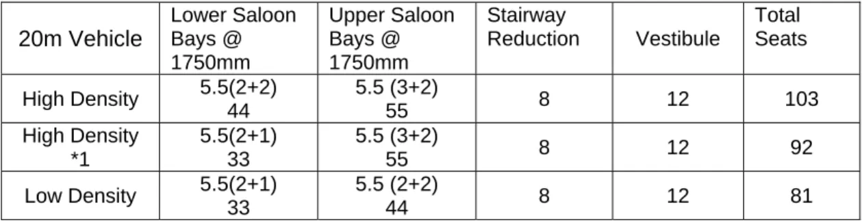
For a nominal 20m vehicle with 14.17m bogie centres by reduction of the central saloon length of the analysis vehicle by the difference in bogie centres of 5830mm giving a 9570mm saloon. Bay length of 5 would be too short and 6 too long. In this case the required adaptation of the vestibule would be too great so a bay layout with an airline arrangement for the balance is used. This gives 5 ½ bays at 1750mm bay lengths. The previously derived bay widths, gives the seating per bay.
20m Vehicle Lower Saloon Bays @ 1750mm Upper Saloon Bays @ 1750mm Stairway Reduction Vestibule Total Seats High Density 5.5(2+2) 44 5.5 (3+2) 55 8 12 103 High Density *1 5.5(2+1) 33 5.5 (3+2) 55 8 12 92 Low Density 5.5(2+1) 33 5.5 (2+2) 44 8 12 81
*1 Included to illustrate the effect of not achieving an acceptable width to the lower saloon. Table 5.2 20m ‘UK’ Double Deck Vehicle seating capacity
5.4 Comparison of seating capacities between UK Sample vehicles and
proposed UK Double deck vehicle
Current UK Vehicle Seats Proposed Double Deck Vehicle Seats % increase 23m class 165 DMU with high
density (3+2) seating 106
23m High Density (2+2) in
Upper and Lower saloons 116 9.4 23m Mark 3 HST Trailer with
(2+2) seating (Great Western) 84
23m Low density (2+2) in Upper
and (2+1) in Lower Saloon 102 21.4 20m class 465 EMU High Density
(3+2) seating 90
20m High Density (3+2) in
Upper and (2+2) in Lower 103 7.3 20m Class 375 EMU Low Density
(2+2) seating 66
20m Low Density (2+2) in Upper
and Lower Saloons 81 22.7
Table 5.3 Percentage increase in capacity with respect to typical UK single deck vehicles (Note: The 2+1 lower saloon high density would achieve a 2% increase.)
To evaluate the increase in capacity for the double deck vehicle a range of current UK vehicles were reviewed and these are detailed in Appendix O. Their summary seating capacity is given above and compared with those established for our Standard Class UK Double Deck vehicles. In arriving at these totals there has been no allowance for first class layout seating, wheelchair space, disabled toilets and train crew areas at this stage. In considering the seating layout the option of all airline seating was evaluated. The benefits were considered marginal, when compared with other assumptions, with just a single extra row being achieved in a 23m vehicle. It was also noted that there is no precedent for the application of airline style in a 3+2 outer suburban application.
5.5 Assessment of Seating Capacity for Proposed UK profile Double Deck
Train Formations
To build up a seating capacity for a whole train estimates were made for the overall configuration of the train and the accommodation of on-board equipment and facilities. The French ‘Analysis’ four car unit was used as a basis for establishing the capabilities of the ‘UK’ Double Deck vehicle.
The French ‘analysis’ four car EMU train has substantial provision within the Driving Coach vehicle floor plan for electrical and auxiliary equipment. The seating capacity of the driving vehicle is 52% of the second class seating vehicle. Similarly, the seating capacity of the part first class layout vehicle is shown as 89% of the capacity of the second class only vehicle. There are no disabled toilet facilities or dedicated wheelchair areas within the four vehicle unit.
To assess a seating capacity for proposed U.K. double deck trains, percentage reductions in vehicle seating capacities will be applied to the previously determined capacity for the ‘standard’ second class trailer vehicle based on the above figures but also taking account of appropriate stock formations and balance of first class and standard class seating for the unit length. (Note: To achieve reasonable levels of seating the first class will include the vestibule seating in that carriage.)
23m Vehicles Driving Coach (1) Trailer Standard Trailer First Driving Coach (2) Total Vehicle Capacity HD 50% 58 100% 116 85% 98 75% 87 4 Car *1 HD 1 68 2 232 0 – assume Driver 2 all first
less 15% 1 74 374 5 Car HD 1 58 2 232 1 98 1 87 475 6 Car HD 1 58 3 348 1 98 1 87 591 Vehicle Capacity LD 50% 51 100% 102 85% 87 75% 76 4 Car *1 LD 1 64 2 204 0-assume Driver 2 all first
less 15% 1 54 322 5 Car LD 1 51 2 204 1 87 1 76 418 6 Car LD 1 51 3 306 1 87 1 76 520
*1 Additional driving coach space allowed in short sets – lighter equipment loading / volume Table 5.4 Seating capacity of typical 23m UK Double Deck trains
20m Vehicles Driving Coach (1) Trailer Standard Trailer First Driving Coach (2) Total Vehicle Capacity HD 50% 51 100% 103 75% 77 75% 77 4 Car *1 HD 1 61 2 206 0 – assume Driver 2 all first
less 25% 1 57 324 5 Car HD 1 51 2 206 1 77 1 77 411 6 Car HD 1 51 3 309 1 77 1 77 514 Vehicle Capacity LD 50% 41 100% 81 75% 61 75% 61 4 Car *1 LD 1 51 2 162 0-assume Driver 2 all first
less 25% 1 47 260 5 Car LD 1 41 2 162 1 61 1 61 325 6 Car LD 1 41 3 243 1 61 1 61 406
*1 Additional driving coach space allowed in short sets – lighter equipment loading / volume Table 5.5 Seating capacity of typical 20m UK Double Deck trains
6 L
ONGT
RAINSThe impact of operating longer trains on the routes has been assessed by using existing data sources for platform lengths, gauging and route configuration. Where work has been identified then it has been sized into a range of tasks and valued in terms of works costs and disruption impact. The work required covers the extension of platforms, relocation of junctions and amendment of station layouts. Work to extend platforms can be straightforward and this is reflected at some locations. However, some will affect the associated junctions, signalling and will require land take. For some locations it is highly likely that additional land will not be available and for these the only available solutions will be to restrict or reduce facilities (junction size). In undertaking the analysis it was noted that issues of passenger loading and junction occupancy would be significant issues not being addressed in this study. A review of junction occupancy will also be required to confirm that the longer trains do not have a severe impact on the overall capacity of the network.
Depot provision has not been reviewed in depth. However, it is expected that
lengthening is likely to be more expensive than the Double Deck option. Examples of work required include, additional land to accommodate the longer train lengths, depot connections would need to be moved and the provision of carriage sidings on the network would need confirming.
High capacity routes in the London Outer Suburban area are currently normally
operated with 12 x 20 metre vehicle EMU trains (243 metres). The Study has examined the scale of infrastructure works that would be needed to increase platform capacity to accommodate trains formed of 16 x 20 metre length vehicles (324 metres) at the principal stations on the selected routes. The individual route section reports contain the results of this study.
To establish a capacity for a 16 car train a review of current layouts in multiple unit trains was undertaken and this is outlined in Appendix O. For evaluation purposes the study uses 240