A New SAW Device Simulator Based on Mason’s Equivalent Circuit Model
Aina Heritiana Rasolomboahanginjatovo, Frédéric Domingue, Adel-Omar Dahmane
Département de Génie Electrique et Génie Informatique Université du Québec à Trois-Rivières
3351, Boul. des Forges, Trois-Rivières, Québec, Canada
[email protected], [email protected], [email protected]
Abstract—This paper presents a new simulator capable of frequency and time domain simulations for surface acoustic wave devices such as surface acoustic wave resonators and reflective delay lines. Developed within Matlab and based on the equations of Mason’s equivalent circuit model, the proposed simulator allows considerable reduction in simulation durations and does not require high computational resources as existing finite element model tools. It is flexible and reliable. Made up of only six files totalizing 40 kilobytes in size, the simulator can be launched on any computer running Matlab.
Keywords-surface acoustic wave; resonator; delay line; frequency domain; time domain.
I. INTRODUCTION
Surface Acoustic Wave (SAW) devices have revolutionized the domain of telecommunications by the possibility to design compact and low cost filters [1]. They are widely used as electronic filters, resonators, delay lines, correlators, convolvers or wireless identification systems integrated into modern communication systems. The evolution of telecommunications standards and requirements, especially for low-loss Radio Frequency (RF) filters used in mobile phones, led to the development of high performance SAW devices, which require flexible, precise and efficient models and simulation tools [2].
Several models including the impulse model, the Equivalent Circuit Models (ECM) [3], the Coupling of Modes (COM) model [4], and the matrix models [5] have been proposed for SAW devices. However, only the ECM, the COM approach and the P-matrix model have been developed to maturity [6]. For its part, the impulse model is not reliable. Indeed, it does not take into account second order effects such as propagation losses, reflections and dispersions.
On the other hand, some Finite Element Model (FEM) tools; e.g., COMSOL [7], Coventor [8], ANSYS HFSS [9]; provide 3D view and 3D simulation for SAW devices. However, the higher the number of fingers is, the longer the simulation duration is, and the higher the required computational resources are. Designers are then faced with a challenge to find a compromise allowing them to reduce the computational complexity of the desired FEM simulation. An alternative consists of implementing the ECM into computer tools such as Ansoft, Spice or ADS. But, again, the same problem can occur when the number of fingers is high.
Despite that, the ECMs are particularly efficient for modeling the interaction between the electrical and
non-electrical components of SAW devices. The analogies between the electrical and mechanical elements are described by W.P. Mason in [10]. The ECM for one pair of fingers he proposed is presented in [11]. As SAW devices are generally composed of several periodic sections; each section consists of a pair of fingers; Mason’s ECM can be easily applied.
From Mason’s ECM equations, it is possible to build, with Matlab, functions that compute the S-parameters of each section, set up the links between sections, and then compute the S-parameters of the entire simulated device. Since most of the computations can be modeled by matrix operations, using Matlab should reduce simulation duration. Therefore, this paper presents a new SAW device simulator based on this approach. The simulator has been implemented into a Matlab program to reduce the required computational power.
The paper is organized as follows: Sections II and III describe the operating principle and the design of the proposed simulator. The reliability of the simulation results is demonstrated in Section IV. Section V highlights the main advantages provided by the simulator.
II. MASON’S ECM AND PROPOSED SIMULATOR A. Mason’s ECM
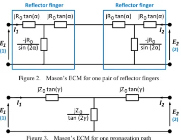
SAW resonators and delay lines are composed of three main components, to wit IDTs (InterDigital Transducers), reflectors, and propagation paths. Each IDT and reflector consists of several pairs of fingers. Mason’s ECMs for one pair of IDT fingers and reflector fingers are illustrated in Fig. 1 and Fig. 2. The ECM Mason proposed for acoustic propagation paths is depicted in Fig. 3 [12].
jR tan(α)0
-jR0 sin (2α)
jR tan(α)0 jR tan(α)0 jR tan(α)0
-jR0 sin (2α) C0 C0 1:1 1:-1 I1 I2 E1 E2 E3 I3 (1) (3) (2)
IDT finger IDT finger
Port (1) and port (2) : Acoustic ports Port (3) : Electrical port Figure 1. Mason’s ECM for one pair of IDT fingers
jR tan(α)0
-jR0 sin (2α)
jR tan(α)0 jR tan(α)0 jR tan(α)0
-jR0 sin (2α)
I1 I2
E1 E2
(1) (2)
Reflector finger Reflector finger
Figure 2. Mason’s ECM for one pair of reflector fingers jZ tan(γ)0 jZ0 tan (2γ) jZ tan(γ)0 I1 I2 E1 E2 (1) (2)
Figure 3. Mason’s ECM for one propagation path
R0 is is the electrical equivalent of the mechanical impedance Z0. C0 represents the electrode capacitance per pair of fingers. α and γ are given by :
α = 0 f f π 2 (1) γ = SAW vf L π (2) where f0 is the center frequency of the SAW device, L is the length of the propagation, and vSAW is the SAW velocity. B. Proposed simulator
The simulator was developed with Matlab Version 7.13.0.564 (R2011b), and is dedicated to the simulation of SAW resonators and delay lines. The operating principle of the proposed simulator is shown in Fig. 4.
Resonance frequency TIME DOMAIN FREQUENCY DOMAIN Equivalent Signature S-parameters TIME DOMAIN FREQUENCY DOMAIN
designed with MatLab designed with MatLab Device parameters
Acoustic velocity Finger width and thickness Number of fingers Density Acoustic aperture Coupling coefficient Dielectric permittivity Device’s structure Materials parameters Number of IDTs Interrogation signal SIMULATION MODULE SIMULATION MODULE electrical impedance
Time domain response
INPUTS OUTPUTS
The major dimensions and parameters of the device to be simulated are first defined by the user. The simulator offers the possibility to run frequency domain simulations and time domain simulations.
Frequency response, impedance parameters and transfer characteristics are provided by the frequency domain simulation module. These include reflection coefficient S33 at the electrical port for SAW resonators, S21 for SAW delay lines, acoustic impedance and equivalent electrical impedance. The impulse response, which can be considered as a signature for SAW identification tags, is calculated by the time domain simulation module.
III. DESIGN OF THE SIMULATOR
The design method (see Fig. 5) is based on a modular approach. Each element of the simulated device is first represented by its Mason’s equivalent circuit. This concerns IDTs, reflectors and propagation paths. Electrical circuit equations are deducted, and then implemented into Matlab functions that extract the S-parameters of each block. Interconnects between blocks are realized by another Matlab function created for this purpose.
Reflector IDT
Reflector Propagation path
1 2
3 2 3
Mason Model equivalent circuit
1 2
3 2 3
Electrical circuit equations
module_3_function ()
module_2_function () module_2_function () module_3_function ()
MATLAB PROGRAM
module_1_function ()
S-parameters / Equivalent electrical impedance
IFFT Mixer Interrogation
signal FFT
The created functions are exported into a Matlab program that computes the S-parameters of the entire simulated device and the equivalent electrical impedance. The results are plotted according to the frequency range set by the user. The time domain simulation capability of the simulator lies in a configurable FFT/IFFT module that predicts the response of the device to a user-defined interrogation signal.
IV. RESULTS
The materials parameters used in the simulations are summarized in Table I. They can be modified by the user, at any time, depending on the properties of the piezoelectric substrate and the metallic layer of the simulated SAW device. The dielectric permittivity of LiNbO3 is given in [12] and the acoustic velocity was extracted from COMSOL simulation.
A. Frequency domain
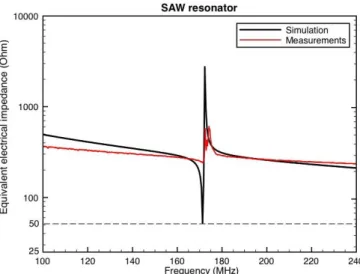
The first simulated device is a one port SAW resonator. It has the same configuration as the SAW device shown in Fig. 5. The dimensions of each element are presented in Table II. The SAW device was simulated with the proposed simulator and then fabricated. Fig. 6 depicts a comparison between simulation and measurement results.
The results demonstrate the reliability of the simulator. The resonance behavior predicted by the simulator matches well with the measurement results (see Fig. 6). For example, the simulator predicts a resonance frequency of 171.3 MHz when the measured resonance frequency is about 171.4 MHz.
Figure 6. Comparison between simulation results and measurement results
The SAW resonator from which the measurements were taken is not perfectly adapted to 50 Ω. The fabrication process is being improved yet.
B. Time domain
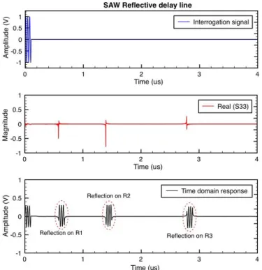
To demonstrate the time domain simulation capability of the simulator, a one port SAW reflective delay line has been simulated. The delay line consists of three reflectors R1, R2, and R3, separated by three propagation paths PP1, PP2 and PP3 (see Fig. 7). The dimensions are summarized in Table III. A short pulse of sinusoidal signal is used as interrogation signal. IDT R1 R2 R3 PP1 PP2 PP3
Figure 7. One port SAW reflective delay line TABLEIII
DIMENSIONS OF THE SIMULATED ONE PORT REFLECTIVE DELAY LINE
Parameter Value
IDT and Reflectors
Finger width 5 μm Wavelength λ 20 μm Finger thickness 100 nm Acoustic aperture 210 μm IDT Number of fingers 150 Reflectors R1, R2, R3 Number of fingers 12, 20, 20 Propagation paths PP1, PP2, PP3 Length 50λ, 70 λ, 120 λ TABLEI MATERIALS PARAMETERS Parameter Value
Piezoelectric substrate LiNbO3
Substrate Type Y-cut, Z-propagating
Dielectric permittivity 27.9
Metallic layer Cu
Acoustic velocity 3 447.7 m/s
TABLEII
DIMENSIONS OF THE SIMULATED ONE PORT RESONATOR
Quantity Value
IDT and Reflectors
Number of IDT 1 Number of reflectors 2 Finger width 5 μm Finger thickness 100 nm Number of fingers 150 Acoustic aperture 210 μm Propagation paths Length 55 μm
Figure 8. Time domain simulation capability of the simulator
The time domain response predicted by the simulator is illustrated in Fig. 8. The output signal is composed of four successive short pulses resulting from reflections at the electrical port and on the three reflectors.
The simulation results are compared with the expected results (see Table IV). The expected time delay of the reflection on Ri (i=1, 2, 3) is given by Ti = 2Li / v, where Li is the one-way path length to Ri and v is the acoustic velocity. Good agreement between expected results and simulation results are observed.
V. ADVANTAGES OF THE SIMULATOR
Several one port resonators have been simulated in order to observe the variation of the simulation duration with the number of fingers in each IDT and reflector (see Fig. 9). The same experiment has been carried out on some one port SAW reflective delay lines by varying the number of reflectors (see Fig. 10). The materials parameters and dimensions of the simulated devices are the same as those presented in Table I, Table II, and Table III. The simulation durations were evaluated with the Matlab instruction
Figure 9. Frequency domain simulation duration
Figure 10. Time domain simulation duration
All simulations were performed using an Intel Core i5-2500 Central Processing Unit @3.30 GHz and 16 gigabytes of RAM. The simulation duration increases with the number of fingers and the number of reflectors. Even for a one port SAW reflective delay line composed of an IDT with 150 fingers and four reflectors with 20 fingers each, the simulation duration is less than one second.
VI. CONCLUSIONS
The proposed new SAW device simulator provides a considerable reduction of the required computational resource and simulation duration. While FEM simulations with COMSOL, or Coventor, or ANSYS HFSS generally last from about ten minutes to several days [13], depending on the complexity of the structure of the simulated device, this simulator allows users to get frequency and time domain simulation results in less than one second.
SAW resonators and SAW reflective delay lines have been simulated. The reliability of the simulator has been demonstrated by comparing simulation results with measurement results. Given that the simulation parameters can be easily modified and a modular approach is used, the new simulator should be able to simulate any SAW device TABLEIV
COMPARISON BETWEEN
EXPECTED RESULTS AND TIME DOMAIN SIMULATION RESULTS Parameter Expected result Simulation result
T1 0.580 µs 0.580 µs
T2 1.461 µs 1.428 µs
AKNOWLEDGMENTS
The authors would like to thank all the members of the LMST team. We especially thank Assane Ndieguene and Issam Kerroum for insightful discussions on acoustic technologies, and Hatem El Matbouly for providing comments on earlier versions of this paper.
REFERENCES
[1] D. C. Malocha, “SAW/BAW Acoustoelectronic Technology
for Filters and Communication Systems”, IEEE Wireless and Microwave Technology Conference, 2010, pp.1-7.
[2] K. Hashimoto, S. Sato, A. Teshigahara, T. Nakamura, and K. Kano, “High-Performance Surface Acoustic Wave Resonators in the 1 to 3 GHz Range Using a ScAlN/6H-SiC Structure”, IEEE Transactions on Ultrasonics, Ferroelectrics, and Frequency Control, vol. 60, no. 3, March 2013, pp. 1-3.
[3] M. Urbanczyk, Z. Waltar, and W. Jakubik, “Interdigital Transducer Analysis Using Equivalent PSpice Model”, Elsevier Science B.V. Ultrasonics, vol. 39, 2002, pp. 595 - 599.
[4] K. Hashimoto, T. Omori, and M. Yamaguchi, “Design Considerations on Wideband Longitudinally-Coupled Double-Mode SAW Filters”, IEEE Ultrasonics Symposium, 2002, pp. 153 - 157.
[5] G. Kovacs, “A Generalised P-matrix Model for SAW Filters”,
IEEE Ultrasonics Symposium, 2003, pp. 707 - 710.
[6] J. Munshi and S. Tuli, “A Circuit Simulation Compatible Surface Acoustic Wave Interdigital Transducer Macromodel”, IEEE Transactions on Ultrasonics, Ferroelectrics, and Frequency Control, vol. 51, no. 7, July 2004, pp. 783-785.
[7] M. Sadeghi, R. Ghayour, H. Abiri, and M. Karimi, “Design and Simulation of a SAW Filter and a New Approach for Bandwidth’s Tuning”, 8th IEEE Int. ASICON, 2009, pp. 642-645.
[8] M. Ghahremani et al., “Surface Acoustic Wave Devices for Ocular Drug Delivery”, IEEE International Ultrasonics Symposium Proceedings, 2010, pp. 872 - 875.
[9] M. Z. Atashbar, B. J. Bazuin, M. Simpeh, and S. Krishnamurthy, “3-D Finite-Element Simulation Model of SAW palladium thin film hydrogen sensor”, in Proc. 2004 IEEE Int. Ultrasonics, Ferroelectrics, Frequency Control 50th Anniversary Conf., pp. 549–553.
[10] W. P. Mason, “Physical Acoustics”, vol. 1A, Academic Press, New York, 1964.
[11] W. P. Mason, “Electromechanical Transducer and Wave Filters”, Second edition, D.Van Nostrand Company Inc, 1948.
[12] B. A. Auld, “Acoustic Waves and Fields in Solids”, vol. I, Wiley, New York, 1973.
[13] A. Stefanescu et al., “Analysis of GaN Based SAW Resonators Including FEM Modeling”, Romanian Journal of Information Science and Technology, vol. 14, no. 4, 2011, pp. 334-345.