Compact Coaxial Probe-Fed CP Substrate Integrated Waveguide
Cavity-Backed Antenna Utilizing Slot Split Ring
Jian-Quan Huang1, Feng Qiu1, Chunzhi Jiang1, Dajun Lei1, *, Zhenghua Tang1, Min Yao1, and Qing-Xin Chu2
Abstract—A circularly polarized (CP) substrate integrated waveguide (SIW) cavity-backed slot antenna is proposed. A slot split ring (SSR) etched on the top metal surface of an SIW resonator is employed to generate the right-handed circularly polarized (RHCP) wave. The proposed antenna is excited directly by a coaxial probe with a proper distance from the symmetric axis of the SSR resonator. A prototype of the proposed CP antenna at the center frequency of 10 GHz is manufactured. As a result, the proposed antenna exhibits the advantages of both conventional planar antennas and metallic cavity backed antennas, including simple structure, compact size of 15.8×15.8 mm2, light weight, easy fabrication, high gain and wide axial ratio bandwidth. It is proved by experiment that an impedance
bandwidth of 10.2% for the reflection coefficient less than −10 dB, an axial ratio (AR) bandwidth of
1.72% for AR less than 3 dB, and a RHCP gain 5.5 dBi have been obtained.
1. INTRODUCTION
Planar circularly polarized (CP) antennas are highly demanded in modern space and communication systems because they can not only reduce the size, volume and cost of the communication systems, but also alleviate multipath distortion and polarization mismatch losses between the receiving and transmitting antennas. Recently, numerous compact and low-profile microstrip CP antennas have been proposed. Perturbation technique, such as loading with extra stub [1], truncating corners [2], etching slots on the patch [3], and series feed coupling [4], is generally used. Meanwhile, to broaden the axial
ratio bandwidth, multiple substrate layers have been applied [5–7]. However, the profiles of those
antennas are high, and the antenna structures are complicated.
Conventional cavity backed antennas have many advantages such as low mutual coupling between antenna elements, low back lobes and gain enhancement. However, traditional cavities employed in antenna are relatively bulky and difficult to integrate with circuits. Substrate integrated waveguide (SIW) antennas have the advantage of low cost, easy integration to circuits and easy fabrication with printed circuit board (PCB) process. Several SIW cavity-backed antenna configurations have been reported. In [8] and [9], a SIW cavity-backed ring slot antenna unified with an SIW feeding network was proposed [8, 9]. By introducing a simply shorting via, the CP generation and a broadband impedance matching characteristic were accomplished. In [10], by exiting two orthogonal resonant modes of an SIW resonator with four radiating slots, a CP SIW slot antenna with high gain was designed. Crossed slot structures were also adopted to achieve the CP radiation characteristic [11–13]. In [12], the gain of a CP x-slot antenna was enhanced by adding a surface mounted horn. Some authors designed new feeding structures to widen the AR bandwidth. In [14], the authors designed a novel feeding transition from stripline to SIW to meliorate the operating bandwidth, and a broad AR bandwidth of the proposed
Received 11 April 2016, Accepted 18 May 2016, Scheduled 28 May 2016 * Corresponding author: Dajun Lei ([email protected]).
1 School of Electronic Information and Electrical Engineering, Xiangnan University, Chenzhou, Hunan, China.2School of Electronic
CP antenna was obtained. However, those SIW cavity-backed antennas were usually loaded with extra feeding networks, which make the antennas larger and not suitable for array application.
In this paper, a circularly polarized substrate integrated waveguide cavity-backed antenna based on a slot split ring (SSR) is proposed. A coaxial probe with a proper offset from the symmetric axis of the SSR is employed to feed the circular SIW cavity-backed antenna directly. Two orthogonal modes of the SSR and SIW resonators are excited, so that circular polarization can be achieved. The total size of antenna is only 15.8×15.8 mm2 owing to no extra SIW feed structure.
2. ANTENNA CONFIGURATION AND DESIGN
A configuration of the proposed antenna is illustrated in Figure 1. A circular cavity with radius of
rSIW is created by an annular array of vertical metallic vias with the diameter of d2 and distance of
pv penetrating through a substrate FR-4 PCB with the relative permittivity 4.4, loss tangent 0.02, and heighth= 1.57 mm. A slot split ring resonator (SSRR) with radius ofrSRRand split of w1 is etched on the upper metal layer of the SIW cavity and excited by a coaxial probe at the distance of xoffset away from the center of the SIW.
(a) (b)
d
1r
SIWx
offsetd
3r
Sl
1w
2r
SSRw
SSRd
2p
vx
y
w
1Figure 1. (a) Top view and (b) bottom view of the proposed antenna (rS = 9.00 mm,rSIW= 7.90 mm,
rSRR = 4.45 mm, wSRR = 1.20 mm, w1 = 0.30 mm, w2 = 0.45 mm, l1 = 1.60 mm, d1 = 1.00 mm,
d2 = 2.30 mm, d3 = 0.60 mm,pv = 1.10 mm, xoffset = 1.12 mm).
(a) (b)
Figure 2 depicts the simulated electric currents of the antenna at two resonant frequencies. As
shown in Figure 2(a), the lower frequency fL is ascribed to the resonance of the SSRR (denoted as
SSRR mode). It can be seen that the terminals and center of the SSRR have the strongest electric current at this resonance frequency. fL can be estimated by the following equation [15]:
fL= c
2π·rSRR−w1+ 2(l1−wSRR) × 1.2
√
εeff
(1)
where c is the speed of light in free space, andεeff = 2εr/(1 +εr) is the effective relative permittivity considering the presence of different dielectric media between the slot and the ground. The simulated electric current distribution of the top layer of SIW resonator at higher resonant frequencyfH is plotted in Figure 2(b). It is due to the resonance of SIW resonator (denoted as SIW mode) at its fundamental mode (TM010-like mode). Considering the perturbation by the split slot ring, the resonant frequency
fH is given by [16]
fH = 0.345c
rSIW√εeff
(2)
wherecandεeff are the same as Equation (1). It is noted that the totalE-fields on the split ring slot on the top layer is roughly orthogonal to those at lower resonance frequencyfL. To obtain a CP radiation,
the offset xoffset of coaxial probe away from the symmetric axis of SSRR is chosen carefully to excite
two electromagnetic orthogonal components with equal magnitudes and phase difference of 90◦. The
proposed antenna radiates a right-hand circularly polarized (RHCP) wave. The left-hand circularly polarized (LHCP) wave can be obtained by mirroring the coaxial probe with respect to y-axis.
The circular polarization band is between the lower resonant frequency and the higher one. Thus,
the operating frequency of the proposed antenna is mainly influenced by radius rSIW of the SIW
resonator and radius rSRR of the split slot ring. Figure 3 shows the influence of the cavity and slot
(a) (b)
(c) (d) 9.0 9.5 10.0 10.5 11.0
-30 -20 -10 0 S11 (dB) Frequency(GHz)
RSIW=7.7mm
RSIW=7.8mm
RSIW=7.9mm
RSIW=8.0mm
9.0 9.5 10.0 10.5 11.0 -30 -20 -10 0 S11 (dB) Frequenc y(dB)
rSSR=4.40mm
rSSR=4.45mm
rSSR=4.50mm
rSSR=4.55mm
9.0 9.5 10.0 10.5 11.0 -30 -20 -10 0 S11 (dB) Frequency(dB)
l1=1.0mm
l1=1.5mm
l1=2.0mm
9.0 9.5 10.0 10.5 11.0 -30 -20 -10 0 S11 (dB) Frequency(GHz)
xoffset=0.8mm
xoffset=0.9mm
xoffset=1.0mm
xoffset=1.1mm
0 3 6 9 12 15 18 Axial ratio(dB )
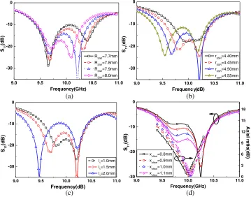
Figure 3. Effects of selected antenna parameters on reflection coefficient and axial ration: (a) diameter
dimensions on the two resonant frequencies. Variation of S11 versus frequency for different values of cavity radiusrSIW is depicted in Figure 3(a). It can be seen by increasing rSIW, and higher resonant
frequency is decreased, and lower resonant frequency is also affected a bit. Moreover, the radius,rSRR, has a great effect on S11 of the slot antenna. Variation of S11 versus frequency for different values of rSRR is illustrated in Figure 3(b). It can be observed that the effect of a small change of rSRR on
the lower resonant frequency is more significant than those on the higher one. Variation of l1 also
slightly affects lower resonant frequency and matching as shown in Figure 3(c). The distance of the
coaxial probexoffset has much influence on magnitudes of two resonant modes and input impedance of
the antenna. Consequently, by tuning these parameters the axial ratio and impedance bandwidth of the antenna can be adjusted, as shown in Figure 3(d). According to the above discussion, in order to achieve a wide axial bandwidth and low return loss, appropriate dimensions of the cavity, split slot ring and location of the excited probe can be achieved by using Ansoft HFSS. All optimized parameters of the proposed antenna are listed in Figure 1.
3. EXPERIMENTAL RESULTS AND DISCUSSION
To demonstrate performances of the proposed antenna, a prototype has been successfully fabricated,
as shown in Figure 4. The S-parameter was measured by Agilent vector network analyzer PNA
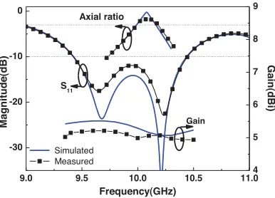
N5230C. Both measured and simulated results obtained by Ansoft HFSS are depicted in Figure 5. The measured result agrees well with the simulated one. The measured impedance bandwidth of 10.12% (for S11 <−10 dB) is greater than the simulated one of 10.1%. The slight difference is mainly caused by fabrication tolerances, and probably a slightly difference of the relative permittivity of the practical substrate compared to the simulated one. The AR, gain and radiation patterns of the proposed antenna were measured in an anechoic chamber by Agilent vector network analyzer ENA E5071. Simulated and measured results of the AR at the boresight direction (z-axis direction) versus frequency are shown in Figure 5. Again measured results are in agreement with the simulated ones. The measured AR
bandwidth is 1.72% (for AR < 3 dB), which is much less than the fractional impedance bandwidth.
The simulated and the measured gains at the boresight direction are also shown in Figure 5. It is seen that the proposed antenna has 5.5 dBi maximum gain within 9.3 to 10.5 GHz at the boresight direction, a very stable 3 dB gain bandwidth of 1.02 GHz. The measured realized gain of the antenna at frequency 10 GHz at the boresight direction is 5.0 dBi, which is slightly lower than that of the simulated result. The simulated and measured far-field radiation patterns in two orthogonal cutting planes at the frequency 10 GHz are illustrated in Figure 6. It is proved that the antenna radiates a RHCP wave with low cross-polarization at the boresight direction. The maximum of radiation in E-planexoz is slightly shifted about 12.5◦.
Figure 4. Photo of the fabricated CP antenna.
9.0 9.5 10.0 10.5 11.0 -30 -20 -10 0 Gain Axial ratio S11 Gain(dBi) Magnitude(dB) Frequency(GHz) Simulated Measured 4 5 6 7 8 9
Figure 5. Measured and simulated reflect coefficient, axial ratio and gain of the proposed antenna.
(a) (b) -30 -15 0 0 30 60 90 120 150 180 210 240 270 300 330 -30 -15 0 z Simulated RHCP Simulated LHCP Measured RHCP Measured LHCP x -30 -15 0 0 30 60 90 120 150 180 210 240 270 300 330 -30 -15 0 Simulated RHCP Simulated LHCP Measured RHCP Measured LHCP y x
Figure 6. Measured and simulated radiation of the proposed antenna at 10 GHz. (a) xoz plane and (b)xoy plane.
Table 1. Comparison of the proposed CP SIW antenna with previously published ones.
ref size BW % AR bandwidth% Peak Gain (dBi) Feed type
[8] 0.88λ0×0.54λ0 9 2.6 8.2 Coax-to-SIW
[9] 1.27λ0×0.83λ0 12.86 2.3 5.75 Microstrip-to-SIW
[11] 1.21λ0×1.21λ0 2.85 0.6 7.8 Microstrip-to-SIW
[13] 0.53λ0×0.53λ0 1.8 0.8 6.5 Microstrip direct
This work 0.53λ0×0.53λ0 10.2 1.72 5.5 Coax direct
4. CONCLUSIONS
In this paper, a very compact X-band circular polarized split-ring-slot SIW back-cavity antenna has been proposed. Two orthogonal modes have been excited by a coax with proper offset from the symmetric axis of SSRR. Consequently, the circular polarization wave is generated. The antenna exhibits the further advantage of small size and light weight. Experimental results prove that the antenna achieves
the impedance bandwidth of 10.12% (for S11 < −10 dB), AR bandwidth of 1.72% (for AR <3 dB),
ACKNOWLEDGMENT
This work was supported by Science and Technology Innovative Research Team in Higher Educational Institutions and the Research Foundation of Education Department (Grant No. 14C1061) of Hunan Province.
REFERENCES
1. Wong, K. L. and Y. F. Lin, “Circularly polarized microstrip antenna with a tuning stub,”Electron.
Lett., Vol. 34, No. 9, 831–832, Apr. 1998.
2. Chen, W. S., C. K. Wu, and K. L. Wong, “Single-feed square-ring microstrip antenna with truncated corners for compact circular polarization operation,” Electron. Lett., Vol. 34, No. 11, 1045–1047, May 1998.
3. Lam, K. Y., K. M. Luk, K. F. Lee, H. Wong, and K. B. Ng, “Small circularly polarized U-slot
wideband patch antenna,” IEEE Antennas Wireless Propag. Lett., Vol. 10, 87–90, 2011.
4. Row, J. S., “The design of a squarer-ring slot antenna for circular polarization,” IEEE Trans.
Antennas Propag., Vol. 53, No. 6, 1967–1972, Jun. 2005.
5. Buffi, A., R. Caso, M. R. Pino, P. Nepa, and G. Manara, “Single-feed circularly polarized aperture-coupled square ring slot microstrip antenna,” Electron. Lett., Vol. 46, No. 4, 268–269, Feb. 2010.
6. Chung, K. L., “A wideband circularly polarized H-shaped patch antenna,”IEEE Trans. Antennas
Propag., Vol. 58, No. 10, 3379–3383, Oct. 2010.
7. Rao, P. H., V. F. Fusco, and R. Cahill, “Wide-band linear and circularly polarized patch antenna
using a printed stepped T-feed,” IEEE Trans. Antennas Propag., Vol. 50, No. 3, 356–361, Mar.
2002.
8. Lacik, J., “Circularly polarised SIW square ring-slot antenna for X-band applications,”Microwave
Opt Technol Lett., Vol. 54, No. 11, 2590–2594, Nov. 2012
9. Kim, D., J. W. Lee, C. S. Cho, and T. K. Lee, “X-band circular ring slot antenna embedded in single-layered SIW for circular polarisation,”Electron Lett., Vol. 45, No. 13, 668–669, June 2009. 10. Hao, Z. C., X. Liu, X. Huo, et al., “Planar high-gain circularly polarized element antenna for array
applications,” IEEE Transactions on Antennas & Propagation, Vol. 63, No. 5, 1937–1948, May
2015.
11. Elboushi, A., O. Haraz, and A. Sebak, “High gain circulary polarized slot-coupled antenna for millmeter wave applications,”Microwave Opt Technol Lett., Vol. 56, No. 11, 2522–2526, Aug. 2014. 12. Pablo, S. O. and L. M. C. Jos´e, “Novel four cross slot radiator with tuning vias for circularly polarized SIW linear array,”IEEE Trans. Antennas Propag., Vol. 62, No. 4, 2271–2275, Apr. 2014. 13. Luo, G. Q., Z. F. Hu, Y. Liang, L. Y. Yu, and L. L. Sun, “Development of low profile cavity backed
crossed slot antennas for planar integration,” IEEE Trans. Antennas Propag., Vol. 57, No. 10,
2972–2979, Oct. 2009.
14. Gao, F., F. Zhang, L. Lu, and Y. C. Jiao, “Wideband Circularly polarised SIW antenna,”
Microwave Opt. Technol. Lett., Vol. 56, No. 11, 2539-2542, Aug. 2014.
15. Chen, W. S., C. C. Huang, and K. L. Wong, “Microstrip-line-fed printed shorted ring-slot antennas for circular polarization,”Microwave Opt. Technol. Lett., Vol. 31, No. 2, 137–140, Aug. 2001. 16. Rao, J. S. and B. N. Das, “Impedance characteristics of transverse slots in the ground plane of a