Int. J. Electrochem. Sci., 10 (2015) 9766 - 9774
International Journal of
ELECTROCHEMICAL
SCIENCE
www.electrochemsci.org
Short Communcation
Flexible Two-in-one Micro Sensor for Integration in Vanadium
Redox Flow Battery
Chin-Lung Hsieh1, Chi-Yuan Lee2,*, Chia-Hung Chen3, Kin-Fu Lin1, Shyong Lee3, Yen-Pu Huang2 and Yun-Min Liu2
1
Institute of Nuclear Energy Research, Taoyuan, Taiwan, R.O.C. 2
Department of Mechanical Engineering, Yuan Ze Fuel Cell Center, Yuan Ze University, Taoyuan, Taiwan, R.O.C.
3
Department of Mechanical Engineering, National Central University, Taoyuan, Taiwan, R.O.C. *
E-mail: [email protected]
Received: 20 July 2015 / Accepted: 9 September 2015 / Published: 30 September 2015
The important physical parameters inside the vanadium redox flow battery (VRFB) are difficult to be measured accurately. They have critical influence on the vanadium redox battery performance and life cycle. Due to the uniformity and expendable nature of solution distribution, it will cause the phenomenon of uneven temperature distribution during the power generation process. As the vanadium pentoxide molecules are solid at normal temperature, once they are formed, the flow of vanadium electrolyte is affected severely. Particularly, the runner is even blocked, so that the heat carried away by the electrolyte flow is reduced, and inside the vanadium redox flow battery temperature rises continuously. However, the present bottleneck is outside, theory and simulation. The real information inside the vanadium redox flow battery cannot be obtained accurately and instantly. Therefore, according to the demand for internal in-situ microscopic diagnosis of vanadium redox flow battery, this work applied the micro-electro-mechanical systems (MEMS) technology to develop a flexible two-in-one (temperature and flow) micro sensor, which is embedded in the vanadium redox flow battery for in-situ microscopic sensing and diagnosis.
Keywords: Flexible two-in-one micro sensor; MEMS; VRFB
1. INTRODUCTION
storage technology development plan and has listed the vanadium redox flow battery in the first place. During the operation of the vanadium redox flow battery energy storage system under ambient temperature and pressure, the heat generated by the battery system can be discharged out efficiently through the electrolyte solution and then outside the system by way of heat exchange. The electrolyte solution is a kind of non-burning and non-explosive aqueous solution with high safety performance. The vanadium redox flow battery is characterized by high current density discharge, long life cycle, quick charging, wide application, low price relative to other energy storage devices and suitability for large static energy storage. Due to the many advantages possessed, the vanadium redox flow battery energy storage system has unlimited development potential in the future energy storage technologies and may change the overall energy arrangement in the future [1, 2].
The vanadium redox flow battery is one of the most representative types of flow batteries. The battery energy storage system mainly utilizes the oxidation-reduction reaction at the battery anode and cathode to conduct the battery charging and discharging. The vanadium ion has four valence states of +2, +3, +4 and +5 that all can exist stably and utilizes the electrolyte to realize the circular flow to convert the chemical energy into electric energy through the oxidation reduction of the active substances in the electrolyte. The vanadium redox flow battery is mainly composed of the proton exchange membrane, carbon fiber felt and bipolar plate where the electrolyte of the anode and cathode is pressurized by a pump and charged into the vanadium redox flow battery’s flow channel to fulfill the electrochemical reaction to release the electric energy and the electrolyte flows back into the liquid storage tank again after the reaction, thus fulfilling the process of charging and discharging through the continuous circular flow of electrolyte [3]. The high-flow-velocity electrolyte reduces the vanadium redox flow battery’s concentration overvoltage under normal circumstances. Although this may improve the efficiency effectively, the high flowrate would result in more power consumption. When the internal temperature of vanadium redox flow battery is increased, the voltage change drops along with it as well [4]. Semiz [5] made membrane from directly copolymerized disulfonated poly(arylene ether sulfone) (BPSH) has been studied for VRFBs. Lee [6] developed the micro temperature sensor to diagnosis high temperature proton exchange membrane fuel cell stack.
2. SENSING PRINCIPLE OF MICRO SENSORS
2.1 Micro temperature sensor
The structural schematic diagram of the micro temperature sensor is as shown in figure 1. The resistance temperature sensor is applied within the linear range of the conductor’s resistance, as shown in Eq. (1).
0 1 1
t
R R T
(1) Eq. (1) can also be adapted to Eq. (2).
0 1
0( )
t
R R
R T
(2)
[image:3.596.235.361.297.554.2]where, the physical meaning of the temperature coefficient (α1) is the sensitivity of sensor.
Figure 1. Structural schematic diagram of micro temperature sensor.
2.2 Micro flow sensor
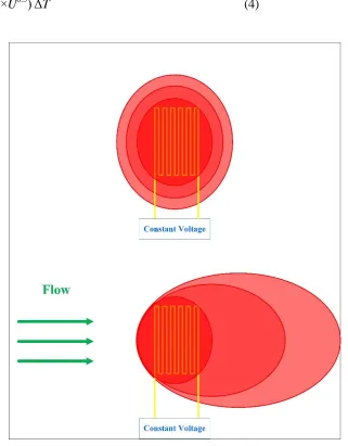
According to the King’s law, the relationship between the thermal energy dissipation rate and the fluid flow velocity is as shown in Eq. (3)
Q = I2×R = I×V = (A+B×Un
) (Ts-To) (3)
where, Q is the electric power supplied by the external power supply; U is the flow velocity of fluid; n is the correlation coefficient of the heat (Q) and the flow velocity (U), which is about 0.5 as learned from the experiment; Ts is the hot-wire temperature; To is the inlet fluid temperature; A is an constant, the heat coefficient transferred by the heater when the flow is zero constantly; B is an constant, the heat coefficient affected by the fluid and heater when the flow is not zero; therefore, Eq. (3) can be adapted to Eq. (4).
[image:4.596.137.458.229.640.2]Q = (A+B×U0.5) ΔT (4)
Figure 2. Schematic diagram of principle of micro hot-wire flow sensor.
3. PROCESS OF FLEXIBLE TWO-IN-ONE MICRO SENSOR
the acidic electrolyte and other advantages of resistance to high temperature and compression, high flexibility and good durability.
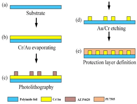
The production process as shown in figure 3, which can be roughly divided into the following steps:
First clean the polyimide base material with acetone and organic methanol solution respectively and then remove the residual methanol, surface dirt and residual grease with deionized water to increase the adhesion of the film metal;
In the process, first conduct the chromium (Cr) evaporation to use it as the adhesive layer between the gold (Au) and the lower insulating layer to increase the adhesion between the gold and polyimide;
Conduct the exposure and development to define and fulfill the sensing graphics of the micro temperature and flow sensors;
Transfer the graphics once again onto the metal film of the chromium (Cr) and gold (Au) by way of wet etching;
[image:5.596.58.535.360.725.2]Finally, spin coat PI 7505 onto and all around the flexible two-in-one micro sensor to fulfill its protective layer and its production with the actual product and the optical micrograph as shown in figure 4.
Figure 4. Diagram of actual product and optical micrograph of flexible two-in-one micro sensor.
3.1 Calibration of flexible two-in-one micro sensor
The flexible two-in-one micro sensor needs to be calibrated before it is embedded inside the vanadium redox flow battery to conduct the microscopic diagnosis to guarantee the reliability of signals. The method of flexible two-in-one micro sensor calibration is to calibrate the micro sensors according to the respective physical quantity individually. The calibration methods are described briefly as follows [8]:
3.1.1 Calibration of micro temperature sensor
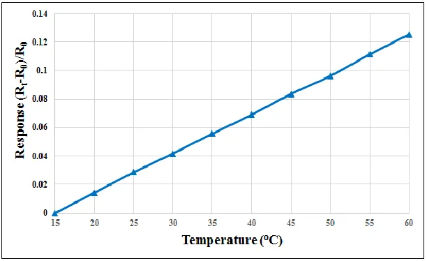
[image:6.596.189.411.70.223.2]After the micro temperature sensor is embedded in the vanadium redox flow battery, use the constant temperature and humidity machine as the temperature calibration reference and maintain the humidity at 100% to simulate the humidity status when the electrolyte flows by to conduct the temperature calibration of the micro temperature sensor. After the control temperature is stable, use the NI PXI 2575 data acquisition device to collect the resistance of the micro temperature sensor in a real-time manner, thus obtaining its calibration curve as shown in figure 5.
[image:6.596.145.451.545.732.2]
3.1.2 Calibration of micro flow sensor
[image:7.596.164.431.244.432.2]The method of flow calibration is to embed the micro flow sensor in the graphite plate of a single flow channel and then provide a stable flow to it. Install an avometer by way of series connection between the power supply and the micro flow sensor to measure the current variation value. The calibration principle is to apply a constant voltage onto the micro flow sensor (heater) to heat up the heater so as to form a stable temperature field. According to the Ohm’s Law, when the voltage is fixed, the resistance decreases and the current would increase relatively, thus the calibration curve of the flow and current variation able to be obtained. The calibration result curve is as shown in figure 6.
Figure 6. Calibration curve diagram of micro flow sensor.
4. EMBEDMENT OF FLEXIBLE TWO-IN-ONE MICRO SENSOR INTO VANADIUM REDOX FLOW BATTERY
[image:7.596.156.446.546.723.2]
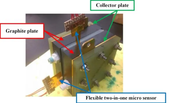
Figure 7 is the diagram of the flexible two-in-one micro sensor embedment into the vanadium redox flow battery. The embedment locations are at the No.2 upstream flow channel and No.2 downstream flow channel of the graphite plate of the vanadium redox flow battery and used to measure its temperature and flow variation inside the battery on the same flow channel generated due to the internal electrochemical reaction downstream and to conduct the microscopic monitoring and diagnosis.
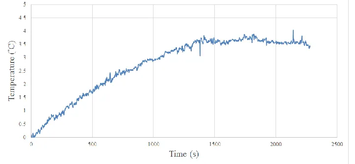
[image:8.596.120.482.262.430.2]Under the conditions of vanadium redox flow battery 30°C and charge constant voltage 1.4V, the flexible two-in-one micro sensors are embedded in cathode flow channel plate of vanadium redox flow battery. When vanadium redox flow battery charge, the local temperature increase is by positive and negative valence of vanadium ions swap as shown in figure 8. Baccino [9] do vanadium redox flow battery charging process of the temperature simulation, which the results are consistent with this study, vanadium redox flow battery temperature of about higher than the outside temperature 3°C to 4 °C.
Figure 8. Local temperature test of vanadium redox flow battery.
5. CONCLUSIONS
This study successfully developed the flexible two-in-one micro sensor applied on the PI base material using the MEMS technology. Its advantages include multiple functions, plug-and-play feature, high precision, high linearity, high sensitivity, strong flexibility, suitability for batch production and fast reaction time. The temperature calibration curve conforms to the calibration within the temperature range of the vanadium redox flow battery under the working status and under the relative humidity of 100% at the same time when the curve is still presented in the linear state. The flow also conforms to the flow of the vanadium redox flow battery under the working status. The micro hot-wire flow sensors of this type are not so uniform for the heat of the temperature field, and may be taken away along with the flow velocity under the liquid environment. Currently, the flexible two-in-one micro sensor is embedded into the vanadium redox flow battery successfully to conduct microscopic sensing and diagnosis inside the battery.
ACKNOWLEDGEMENTS
2221-E-155-033-MY3, 103-2622-E-155-006-CC2, 103-2622-E-155-018-CC2 and 104-2622-E-155-004. In addition, we would like to thank the YZU Fuel Cell Center and NENS Common Lab, for providing access to their research facilities.
References
1. O. D. Akinyele, K. R. Rayudu, Sustainable Energy Technologies and Assessments 8 (2014), 74-91.
2. H. Chen, N. T. Cong, W. Yang, C. Tan, Y. Li, Y. Ding, Progress in Natural Science 19 (2009), 291-312.
3. J. K. Lee, H. Y. Chu, Vacuum 107 (2014), 269-276.
4. Y. Zhang, J. Zhao, P. Wang, M. Skyllas-Kazacos, B. Xiong, R. Badrinarayanan, Journal of Power Sources 290 (2015), 14-24.
5. L. Semiz, N. D. Sankir, M. Sankir, International Journal of Electrochemical Science, 9 (2014), 3060-3067.
6. C. Y. Lee, F. B. Weng, F. H. Liu, C. P. Chang, C. K. Cheng, International Journal of Electrochemical Science, 8 (2013), 12580-12589.
7. B. Xiong, J. Zhao , Z. Wei, M.Skyllas-Kazacos, Journal of Power Sources 262 (2014), 50-61 8. C. Y. Lee, C. H. Chen, C. L. Hsieh, K. F. Lin, S. Lee, T. L. Chen, Y. P. Huang, International
Journal of Electrochemical Science 10 (2015), 3185-3191.
9. F. Baccino, M. Marinelli, P. Nørgård, F. Silvestro, Journal of Power Sources 254 (2014), 277-286.