International Journal of Innovative Technology and Exploring Engineering (IJITEE) ISSN: 2278-3075, Volume-8 Issue-8 June, 2019
Abstract: This article aims to design a patch antenna (PA) that can resonate at three bands. Its architecture contains circular ring enclosed by a flower shaped aperture with circular notch at its center, best suitable for wireless communication applications. Central notch improves the reflection coefficient of designed patch antenna. Proposed design exhibiting three resonating band characteristics, first one is at 2.52 GHz with operating bandwidth (OBW) of 0.25GHz, second one is at 4.58 GHz with OBW of 0.57GHz and third one is at 7.2 GHz with OBW of 0.71GHz respectively. Proposed antenna is exhibiting a maximum peak gain of 3.8dBi at 2.52GHz operating frequency over FR4 substrate of thickness 1.6mm. The over all size of antenna is 41.8X28X1.6 mm3..
Index Terms: Ultra-wideband (UWB), Triple band, Flower shaped antenna.
I. INTRODUCTION
The growth in wireless communication technology giving challenges to antenna engineers to design a system that can perform multiple number of task and compatible for existing technology. So multi-band antennas attracting the attention of antenna researchers. Here single antenna covers more number of frequency bands [1]. In [2], triple band antenna with microstrip slot was proposed. In [3] Zhai proposed circular arc shaped tunable antenna was proposed to achieve triple band characteristics. In [4], asymmetric dipole antenna with C-shaped parasitic strip is proposed by tuning its strips it will produce double and triple band characteristics. In [5], antenna incorporated by two opposite triangular rings can produce triple band and triple polarization. In [7], circularly polarized slot antenna proposed for triple wide band applications. Similar and some extended version of research was presented in [8-13]. Current study concentrates on the development of simple triple band antenna. Current architecture consists of a circular ring incorporated by four petals arranged 90 degrees apart. To enhance the performance of antenna ground size is made to half instead of covering full.
II. DESIGNMETHODOLOGY
Fig 1 showing the iterations to design proposed patch antenna. During first iteration circular ring is designed, next iteration petal1 is designed copy of it (that is petal2) is arrange 90 degree to petal1 similarly third petal3 is arranged 90 degree to patel2 and finally petal4 is arranged 90 degree to patel3. During final iteration, a circular notch is made at the
Revised Manuscript Received on June 05, 2019.
Dr. Praveen Kumar Kancherla, Associate Professor, Dept of ECE, CMR Institute of Technology, Kandlakoya, Hyderabad, T.S.
center of radiating ring. The complete architecture is etched on top surface of FR4 substrate with thickness of 1.6mm backed by half ground of dimension 41.8X28mm2.
Table1 : Design parameters corresponding values in mm.
Paramete
r Value Variable Value
Ws 28 R1 12
Ls 41.8 R2 10.5
Lg 16 Lf 1.5
Wg 28 Wf 16
H 1.6 O 2
(a) (b) (c) (d) (a) iteration 1 (b) iteration 2 (c) iteration 3
(4) Proposed antenna.
Fig 1: Development stages of proposed antenna.
Fig.2(a) is showing a single petal design and its corresponding coordinate system, detailed dimensions and size for better understanding its structure.
(a) Proposed antenna
Triple Band Edge Feed Patch Antenna; Design
and Analysis
(b) Structure of the Petals
Fig 2 : Dimensions
The final architecture is depicted in Fig. 2(a), corresponding design values are presented in Table.1
III. RESULTSANDDICUSSIONS
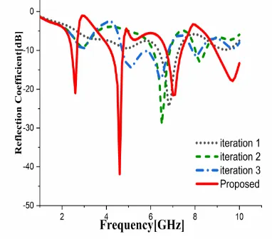
Fig 3 showing the simulated results of return loss characteristics (S11) of PA at every iteration. The
[image:2.595.325.531.218.363.2]fundamental structure of edge feed circular disk PA over half ground is exhibiting operating frequency of 6.33GHz - 7.27GHz with an OBW of the 0.9 GHz, shown in Fig 3 with black colour small dots. During second iteration PA architecture is as shown in Fig 1(b) where the aperture of antenna contains a circular ring. This structure is exhibiting an operating frequency of 6.1GHz – 6.8GHz with an OBW of 0.7 GHz, shown in Fig 3 with green colour long dots. During third iteration the PA architecture is as shown in Fig 1(C), where single petal was incorporated. This structure is exhibiting an operating frequency varying from the 4.7GHz - 6.8GHz, shown in Fig 3 with blue colour long dots.
Fig 3: Return loss characteristics PA at each iteration.
After final iteration, proposed antenna architecture is achieved as shown in Fig 1(d), is exhibiting triple frequency bands first resonance band is ranging from 2.4GHz -2.62GHz with an operting bandwidth of 0.22GHz and second resonance band is ranging from 4.18GHz - 4.78GHz with an OBW of 0.55GHz and finally third resonating band ranging from 6.7GHz - 7.3GHz with an OBW of 0.6GHz. Corresponding reflection coefficients (S11) are as follows -21
dB, -41 dB and -29 dB. Hence proposed and designed antenna is best covers WLAN, ISM, INSAT and X-band applications.
A. Parametric Study:
At this stage few parameters which are effecting operational characteristics of antenna more are considered its influence was studied to determine the optimum parametric values. The key parameters considered here are (i) length of the ground structure, (ii) feed width, (iii) second circle radius and (iv) radius of slot. While studying one parameter effect during that time remaining parameters are kept at its fixed position. Reflection coefficient is considered as operational characteristic of antenna and obtained results are shown in Fig 4 - 7. Ground length is varied from Lg= 15mm-18mm, when ground length is at 17mm triple band output was observed.
Fig 4: Effect of ground length on triple band characteristics. Feed line width is varied Wf= 1mm-2.5mm with an increment of 0.5mm at each step. When feed line width is at 2mm triple band characteristics were observed and obtained results were presented in Fig.5.
Fig 5: Effect of second circle radius on triple band characteristics.
[image:2.595.71.262.428.596.2] [image:2.595.309.521.447.596.2]International Journal of Innovative Technology and Exploring Engineering (IJITEE) ISSN: 2278-3075, Volume-8 Issue-8 June, 2019
[image:3.595.348.491.122.578.2]Fig 6: Effect of radius of the circle R2 on triple band characteristics.
Fig 7. Effect of radius of slotted circle ‘O’ on triple band characteristics.
The slotted circle (notch) radius is altered from O= 3mm-6mm with an increment of 1mm at each step. When slotted circle radius is at 4mm triple band characteristics were observed and obtained results were presented in Fig.7.
B. Surface Current Distribution
Surface current concentration on the proposed antenna, when operating at three center frequencies that is 2.52GHz, 4.58GHz and 7.2GHz is simulated and obtained results were analyzed and presented in Fig.8. From the figure it was understood that surface current is more on the circular ring when compared with the flower structure when proposed antenna is operating at 2.52GHz. As the progress in antenna operating frequency up to 4.58GHz from 2.52GHz, the surface current passes to flower structure through circumference of circle and also maximum radiation occur from feeding edge of the patch, when operating frequency progresses from lower to higher.
(a)2.52GHz (b) 4.58GHz (c) 7.2GHz Fig 8:Concentration of surface current, when progress in
resonating frequency of proposed structure.
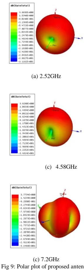
C.GAIN
Polar gain of triple band PA with edge feed is shown in Fig.9. It is observed a maximum peak gain of 3.86dB at 2.52GHz, 3.62dB at 4.58GHz and 3.77dB at 7.2GHz.
(a)2.52GHz
(c) 4.58GHz
(c) 7.2GHz
Fig 9:Polar plot of proposed antenna.
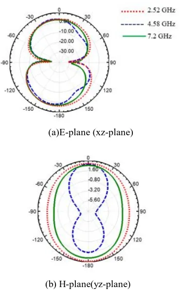
D. RADIATION PATTERN
[image:3.595.82.257.228.368.2] [image:3.595.47.277.653.782.2](a)E-plane (xz-plane)
[image:4.595.78.263.48.346.2](b) H-plane(yz-plane)
Fig 10: Simulated Radiation patterns of proposed antenna.
E. MEASURMENT SETUP
(a)Network analyzer testing
[image:4.595.320.533.50.213.2](b) Top view (c) Rare View
Fig 11: Fabricated antenna and corresponding Measurement setup.
[image:4.595.300.557.299.471.2]Fig 12. Return loss characteristics of simulated and measured results.
Table 2: Tabulation of simulated and measured results for
better judgement of proposed antenna performance.
S.No Parameter Simulated Measured
1
Frequency range (GHz)
2.4-2.62 2.41-2.56
4.18-4.78 4.25-4.52
6.7-7.3 6.8-7.35
2 Bandwidth
(GHz)
0.22 0.15
0.55 0.27
0.6 0.55
3 S11(dB)
-21 -17
-41 -16
-29 -18
4 Impedance
band width (%)
8 6
12 6.9
8 7
IV CONCLUSION
The circular ring enclosed flower shaped aperture with circular notch at center having edge feed PA over FR4 substrate is operating at three operating bands was successfully designed. It radiation characteristics (simulated results) were presented in comparison with measured results, to judge its performance. .
REFERENCES
1. Zaman, W., Ahmad, H., &Mehmood, H. (2018). A miniaturized
meandered printed monopole antenna for triband
applications. Microwave and Optical Technology Letters, 60(5),
1265-1271.
2. Dang, L., Lei, Z. Y., Xie, Y. J., Ning, G. L., & Fan, J. (2010). A compact
microstrip slot triple-band antenna for WLAN/WiMAX
applications. IEEE Antennas and Wireless Propagation Letters, 9,
1178-1181.
[image:4.595.104.241.580.699.2]International Journal of Innovative Technology and Exploring Engineering (IJITEE) ISSN: 2278-3075, Volume-8 Issue-8 June, 2019
4. Badugu P. Nadh, B T P Madhav, Munuswamy S. Kumar, Manikonda V. Rao, TirunagariAnilkumar, Asymmetric Ground Structured Circularly Polarized Antenna for ISM and WLAN Band Applications, Progress in Electromagnetics Research M, Vol. 76, 2018, Pp 167–175.
5. T V Ramakrishna, B T P Madhav, G Manmohan, M Pavithra, Triple Band linearly polarized Square Slotted Micro strip Antenna for X – Band Applications, Far East Journal of Electronics and Communications, ISSN: 0973-7006, Vol 15, No 2, Dec-15, pp 99-110.
6. S. S. Mohan Reddy, B. T. P. Madhav, B. Prudhvinadh, K. ArunaKumari, M. V. S. Praveen, M. Hemachand, E. Mounika, Arc-Shaped Monopole Liquid-Crystal Polymer Antenna for Triple-Band Applications, Lecture Notes in Electrical Engineering, ISSN:1876-1100, Vol 471, 2018, pp 797-806.
7. G Jyothsna Devi, U Ramya, BTP Madhav, Triple Band Monopole Frequency Reconfigurable Antenna for Wireless Medical Applications,Indian Journal of Public Health Research & Development, June 2018, Vol. 9, No. 6, pp 279-284.
8. Zhang, T., Hong, W., & Wu, K. (2015). A Low-Profile Triple-Band
Triple-Polarization Antenna with Two Triangular Rings. IEEE Antennas
And Wireless Propagation Letters, 14, 378-381.
9. Li, L., Zhang, X., Yin, X., & Zhou, L. (2016). A compact triple-band
printed monopole antenna for WLAN/WiMAX applications. IEEE
antennas and wireless propagation letters, 15, 1853-1855.
10.K.Praveen Kumar, Dr Habibulla Khan " Surface wave suppression band, In phase reflection band and High Impedance region of 3DEBG Characterization" IJAER, Vol 10, No 11, 2015.
11.K.Praveen Kumar, Dr. Habibulla Khan, "Design and characterization of Optimized stacked electromagnetic band gap ground plane for low profile patch antennas" IJPAM, Vol 118, No. 20, 2018, 4765-4776.
12.K.Praveen Kumar, Dr. Habibulla Khan "Optimization of EBG structure for mutual coupling reduction in antenna arrays; a comparitive study"
IJET, Vol-7, No-3.6, Special issue-06, 2018. page 13- 20.