5-31-1950
Effect of flow rates on holdup in a liquid-liquid
extraction spray column for the system
hexone-water
Howard Carl Peterson
Iowa State UniversityFollow this and additional works at:http://lib.dr.iastate.edu/ameslab_iscreports
Part of theMaterials Science and Engineering Commons, and theMechanical Engineering Commons
This Report is brought to you for free and open access by the Ames Laboratory at Iowa State University Digital Repository. It has been accepted for inclusion in Ames Laboratory ISC Technical Reports by an authorized administrator of Iowa State University Digital Repository. For more information, please [email protected].
Recommended Citation
Peterson, Howard Carl, "Effect of flow rates on holdup in a liquid-liquid extraction spray column for the system hexone-water" (1950). Ames Laboratory ISC Technical Reports. 6.
the system hexone-water
Abstract
An investigation of liquid-liquid spray column operation using the system hexane-water was made, with particular emphasis on the relationship between flow rates and holdup (volume fraction of dispersed phase in the column). A preliminary study was made in a 1 3/4 inch outside diameter column to determine the mechanism of drop formation. At low dispersed phase rates, drops of equal size formed at the dispersion plate. As the flow increased, a cone of dispersed fluid built up into the continuous phase and the drops broke off the tip of this cone in a variety of sizes. It is possible from tests made on this small column (with few holes in the dispersion plate) to predict the performance of a plate with a large number of holes with respect to drop formation and approximate drop size distribution. This prediction is from the pressure drops across the plate in both cases.
Disciplines
Engineering | Materials Science and Engineering | Mechanical Engineering
f
·
1
',,.
' fISC-96
EFFECT OF FLOW RATES ON HOLDUP IN A LIQUID-LIQUID EXTRACTION SPRAY COLUMN FOR THE SYSTEM HEXONE-WATER
By
Howard Carl Peterson
May 31
1.1950
Iowa State College
Ames Laboratory
-Work performed under Contract No. W-74Q5 .. eng-72
PRINTED IN U.S.A. PRICE 20 CENTS
EFFECT OF FLO\JY RATES ON HOLDUP IN A LIQUID-LIQUID EXTRA.CTION SPRJ. Y COLUMN FOR THE SYSTEM HBXONE-WA TERl
by Howard Carl Peterson
AffiTRACT
an investigation of liquid-liquid spray column operation using the system hexane-water was made, with particular emphasis on the relation-ship between flow rates and holdup (volume fr-action of dispersed phase in the column). A preliminary study was made in a 1
J/
4 inch outside diameter column to determine the mechanism of drop formation. At low dispersed phase rates, drops of equal size formed at the dispersion plate. As the flow increased, a cone of dispersed fluid built up into the continuous phase and the drops broke off the tip of this cone in a variety of sizes. It is possible from tests made on this small column (with few holes in the dispersion plate) to predict the performance of a plate with a large number of holes with respect to drop formation and approximate drop size distribution. This prediction is from the pres-sure drops across the plate in both cases.It was observed that when the hexane was dispersed, it wet the plate and formed large irregular drop sizes. A plate was made with protruding metal tips, tapered so that the horizontal area around the hole was a minimum. This plate functioned very satisfactorily.
The major portion of the investigation was carried out on a
6
1/4 incn inside diameter column. The column was an 8 foot length of Pyrex pipe with metal end sections. A dispersion nozzle with interchangeable plates was in one of the end sections. Nozzle plates with 22, 89,357
1/16 inch holes and 89 1/32 inch holes were studied in the course of this investigation. The study was divided into two phases, water dispersed in hexane and hexane dispersed in water.When water was dispersed in hexane, it was .found that the holdup inc:Peased rapidly with dispersed rate with the 22 1/16 inch hole and 89 1/32 inch hole plates. The holdup increased to a point and then abrl..lptly leveled off. This point was called the "break point." Considerable coalescence occurred past the bre~k point. Carryover of the hexane in the water phase was greater after the break point was reached. This phenomenon of carryover is believed to be character-istic of the liquid system used and not of the column.
lJ).LS. thesis submitted June 1, 1950. This work was performed under
A break point was observed when using the plate with 89
1/16
inchholes, but at a greater dispersed rate than with the 22
1/16
inch holeplate. No break point was observed with the
357 1/16
inch hole plate. Little or no carryover occurred when the357 1/16
inch hole plate wasused. The plate with the fewer number of holes produced a larger holaup
for the same dispersed rate than plates with a larger number of holes.
The drop size was larger and more uniform with the larger number of
holes.,
Similar action was observed with the hexane dispersed in water with the exception that no abrupt break point occurred, but there was a
leveling off of the holdup as the dispersed rate increased and less carryover of hexane with the water phase.
INTRODUCTION
In the field of liquid-liquid extraction, experimental
investi-g.ations have been prlinarily concerned with the determination and esti-mation of mass transfer coefficients. Although some work has been done
in the study and evaluation of equipment, there are still problems to
be solved. This is particularly true in the case of spray columns, ·
in which one liquid phase is dispersed by a suitable device in another. The dispersed phase rises or falls through the continuous phase under
the influence. of the difference of density of the two liquids. The spray column represents a relatively simple and useful contacting device which may be readily applied to extraction operations on an
engineering scale. It is analogous to spray type gas absorption eq~ip
ment.
The object of the present studywas the test operation of a
laboratory countercurrent liquid-liquid extraction spray column. Dispersion nozzle design and its effect on holdup was studied. 1~jor interest was placed in the relationship between the flow rates of the liquids used and the holdup (the volume fraction of disr~rsed phase
in the column) • Holdup is related to the interfacial area of the
phases in the column. Holdup is also a measure of the time of contact between the phases. Since extraction rates are· dependent on the inter-facial area and the time of contact, the holdup is an important
consideration in the design of an extraction system. There are other
important factors affecting extraction rates, such as the relative solubilities of the solute in each of the phases, the diffusivity of
Appel and Elgin (1) reported holdup and flow rates on 38 runs for the system toluene-water. Johnson and Bliss (7) presented 109 runs for which holdup was tabulated. Elgin and Blanding (3) were concerned with
column performance and listed conditions of the llflooding point" but presented no values of holdup. Grandjean (5) reported holdup and flow rates for 30 runs on the system hexane-water.
Hunter and Nash (6) reviewed the theory of liquid-liquid extraction and ev.iluated the equipment available, but made no mention of spray columns. Appel and Elgin (1), Elgin and Brown~ng (4), Johnson and Bliss (7), and Elgin and Blanding (3) made advances in the theory of operation of the spray column. Their conclusions were drawn from observation of ·the column under operating conditions and were an attempt to evaluate its performance.
Previous investigators have all used columns of a diameter under
3 inches with the exception of Row, Koffolt1 and Withrow (8) and
Grandjean
(5),
who used9
inch and6
inch diameter columns respectively.EXPERIMENTAL METHODS •
. ,
This investigation was carried out on two spray columns~ one a 1
3/4
inch O.D. by 20 inches long, hereafter referred to as the small column, and the other a6
1/4 inch I.D. column 8 feet long} to be referred to as the large column. The small column was used for a study of nozzle design and operation and for qualitative study of drop formation and drop size. A relationship between pressure drop across the nozzle nlate~ drop formation, and column operation was alsoobtained in the ~mall column.
The large column was used for all countercurrent work and all data relating flow rates to holdup were recorded with test operation of this equipment.
Small Column
The small column was mounted on a ring stand. One end was closed
the dispersion nozzle connected. A nozzle plate was made from sheet metal and suitable holes were drilled in this plate. The dispersion nozzle plate was soldered to a 3/4 inch stainless steel coupling, which was in turn connected, through suitable fittings, to a 1/4 inch
pipe, which was the inlet of the dispersed phase. In this way, the nozzle plate could be replaced with little effort and yet produce the desired results.
A Woulff bottle, raised manually with a rope and pulley, was used as the feed tank to the column. The dispersed phase was the only feed to the column and the only outlet was at the top. Rubber tubing served as feed lines. The nozzle was placed at the top or the bottom
of the column, depending upon which phase was dispersed.
For the pressure drop studies, a differential manometer was placed across the entrance to the dispersion nozzle and an outlet from the column, just even with the nozzle itself (Figure 1). Carb~ tetra-chloride was used as an indicating fluid when the water was dispersed, and benzyl acetate was used when hexane was dispersed.
Nozzle plates with 1, 5, and
9
1/16 inch holes were studied in the column. Plates made of brass, galvanized iron, nickel, leadtin, monel metal, and unglazed porcelain were studied in this column.
A plate was made ·which contained
5
1/8 inch copper rivets, each witha 1/32 inch hole drilled in and the end of rivet tapered, so the
horizontal area around the hole was a minimum.
During the tests to develop the nozzle design, the action of the dispersed phase at the plate was visually observed. The nozzle plate was changed until suitable action of the drops from the holes was
obtained.
Drop formation and column operation were visually observed
while pressure drop readings and flow rates of the dispersed phase were being recorded. Flow rates were made by measuring the volume of fluid
leaving the column over a given period of time.
Large Column
WOULFF BOTTLE
r-I_
t/
NOZZLE PLA TE/
.
i.-"-'
WANOWETEit
The column proper was a
6 1/4
inch I.D., 8 foot length of Pyrexpipe manufactured by the Corning Glass Company. The ends
of
the pipewere flanged, which improved the glass to metal connections at the ends
of the column. The end sections were of the design suggested by Elgin
(2,
3).
The advantages of the use of this design are:(1)
the conicalshape of the dispersed phase entry section (there is no restriction in
flow area for the contin'Uous phase as i t passes the dispersion nozzle),
(2) the circular v1eir of the other section behind which the continuous
phase is introduced and over which this phase flows (preventing
channeling and excessive turbulence), and (3) the enlarged cross
sectional area in both section.s (reducing the velocity of the fluids
and effecting a better separation of the phases).
The end sections were fabricated from 1/8 inch stainless steel
(no.
304)
plate and were joined to the glass pipe by suitable flanges. Both sections had observation windows in them. The lower end sectionvms supported by a metal stand resting on the floor~ while the upper
section was suspended by four turn-buckle rods from the ceiling. In this way the glass pipe itself carried none of the weight of th~ end
sections or the piping. All connections from the outlets of the end
sections to ~he piping were made through
3/4
inch flexible bronze hoseso that any v!:brations of the piping would not be transmitted to the
'I
glass column.
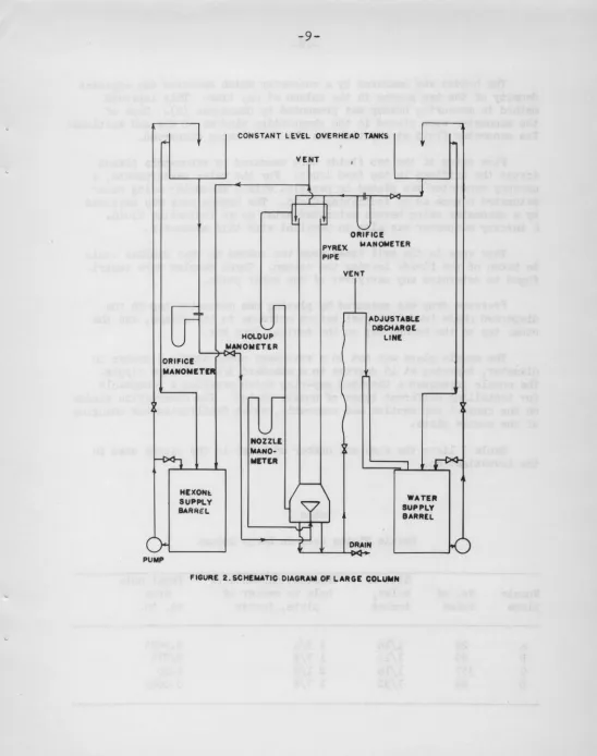
Figure 2 schematically illustrates the flow circuit for the
equip-ment used in this study. Both the continuous and dispersed phases to
the column were .fed through
3/4
inch stainless steel pipe from twC'constant level O'rerhead
15
gallon tanks • . These two tanks were 9 feetand
14
feet 3 inches above the top of the column for the light liquidand heavy liquid respectively. Feed to these tanks was delivered from
the corresponding supply and receiving tanks
(55
gallon stainlesssteel barrels) by positive displacement circulating pumps. Discharge
from the column for each liquid was returned to the corresponding
supply barrel. Separate product barrels were not used since no
extra-action was taking place. Control valves were placed as illustrated. in
Figure 2. Two sharp-edge orifice plates, flanged into the feed lines
and calibratea in place, provided the means of metering the two liquid
phases.
The interface level between the two phases was in the end section
where the continuous phase was introduced. The interface level was
controlled by a flexible leg on the heavy liquid exit line from the
column. This procedure was in agreement with the methods used by the
majority of the previous investigators. The control consisted of a
vented and inverted U-arm which could be lowered and raised manually
to produce changes in the interface level. One leg of the U was a
flexible bronze hose which was connected by pipe to the exit of the
column, the other leg of the U was a one inch pipe, which slipped
ORI,-IC!
MANON!TP
HEXONt.
SUPPLY BARR£L
c>L---..J
PUMP
CONSTANT LEVEL OVERHEAD TANKS
"
r
7 T -n·r l
~
O~IC!'--'
NOZZLE
MANO· NITER
PYREX PIPE
MANOMETER
VENT
....-'- ADJUSTABLE
DISCHAIIIOE LINE
DRAIN
1
WATER
SUPPLY BARREL
[image:11.566.11.559.22.716.2]method in measuring holdup was presented by Grandjean (5). Taps of
the manometer were placed in the observation windows of the end sections.
The manometer fluid at any time was the fluid being dispersed.
Flow rates of the two fluids were measured by manometers placed
across the orifices in the feed lines. For the water measurements, a mercury manometer was placed in parallel with a manometer using water
saturated hexane as an indicating fluid. The hexane rate was measured
by a manometer using hexane saturated water as an indicating fluid. A mercury manometer was also in parallel with this manometer.
Taps were in the exit lines from the column so that samples could
be taken of the fluids leaving the column. These samples were
centri-fuged to determine any carryover of the other phase.
Pressure drop was measured by placing one manometer tap in the
dispersed phase feed line just before entrance to the column, and ~9e
other tap on the holdup tap on the conical feed box.
The nozzle place was set in a stainless steel nozzle 5 inches in
diameter, tapering at
45
degrees to a standard3/4
inch pipe nipple.The nozzle possessed a threaded cap-ring which provided a receptacle for installing different types of nozzle plates. The observation window
on the conical end section was removable, which facilitated the changing
of the nozzle plate.
Table I lists the size and number of holes in the plates used in
the investigation.
Table I
Nozzle Plates Used in Large Column
Size of Greatest distance of Total hole
Nozzle No. of holes, hole to center of area
plate holes inches plate, inches sq. in.
A
22
1/16
1
3/4
0.0
675
B
89
1/16
1
7/8
0.275
c
357
1/16
2
1/8
1.10
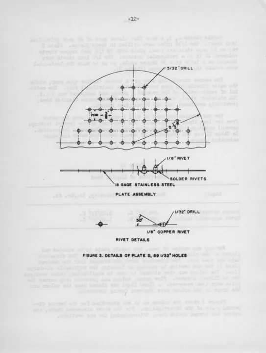
[image:12.564.11.557.22.697.2]Nozzle plates A, B, C were flat plates macie of 20 gage galvanized iron sheet. The l/16 holes were drilled in these plates. Plate D
was an 18 gage stainless steel plate with 89 1/8 inch copper rivets
soldered in it in a rectangular pattern. The 1/8 inch rivets were tapered on a lathe at a 30 degree angle, so as to make the horizontal area around the hole a minimum (Figure
J).
The hexone circulating pump was a bronze turbine type pump, while
the water circulating pump was a Vlorthite centrifugal PJump. The mater-ial of construction of the rema.inirJg piping and equipment was S .A .E. 304 stainless steel, with the exception of the bronze flexible hose,
previously mentioned, and the Pyrex glass column.
The two liquids employed in this investigation were tap water from the Iowa State College mains and technical hexone (methyl isobutyl
ketone) manufacturr'd by the Carbide and Carbon Chemicals Corporation.
In Table II are the properties of hexone saturated water and water saturated hexone.
Liquid
Hexone saturated water
v"fa te r sat UI"d. ted hex one
Table II
Properties of Liquids Used
Density, g/cc
.996/26°
c.
• 797/26°c.
Viscosity, lb./hr. ft.
2.20/25°
c.
1.46/25°c •
For any one series of runs, the nozzle plate to be studied was
placed in the column and the continuous rate was set. The dispersed
rate was then set. 1'he interface level was brought into the desired
place in the end section by raising.or lowering the adjustable discharge
line. The column was then allowed to come to equilibrium, which required ten to fifteen minutes. Flow rates, holdup and pressure drop across the
plate were then recorded. A flood light was placed near the column and
the drops in the column were observed during operation.
Figure 2 shows the column as it was assemb~ed for the hexone
dis-persed phase of the investigation. For the water dispersed study, the
[image:13.564.8.552.31.709.2]PLATE ASSEMBLY
~32"DRILL
1/8" COPPER RIVET RIVET DETAILS
FIGURE 3. DETAILS 0' PLATE D, It 1112• HOLIES
I
[image:14.570.7.551.20.741.2]EXPEf'I.lv!ENTAL PcF.SULTS
Nozzle Design Studies
It was observed that when hexane was dispersed in water in the
small column, the hexane tended to wet the plate, agglomerate, and
break away in large irregular drops. This is in agreement with other
investigators (6, 9). vhen the water was dispersed in hexane, the
water did not wet the plate, but formed drops at the holes, which
broke away in equal size. This is the condition to be desired.
Plates made of brass, galvanized iron, nickel, lead, tin, monel
metal and unglazed porcel~in were tested in the small column. Hexone
wet each of these plates to about the same degree.
Since the hexane spread over the area of the plate, the hexane
would form equal size drops if the horizontal area around the hole
were a minimum. This led t<? the design of the rivet plate. A 1/32 hole was drilled in a l/8 inch copper rivet and the rivet was tapered, so to make the horizontal area minimum. The rivets were then soldered through holes in a sheet of metal. This plate formed equal size drops and no wetting of the rivets was noted. Apparently with the rivet
plate, a smaller total volume is required to form the same contact
angle between the hexone and plate than with the flat plate. The
fabrication of such a rivet plate was laborious and only one such
plate was made for use in the large column.
It was found that when a galva.nized iron plate was soaked in strong caustic solution, hexane would not wet the plate. However,
water would wet this plate. After the plate was placed in acid, the
hexane vrould again wet the plate. The caustic treatment apparently
makes the surface more hydrophilic; therefore, the limiting contact
angle between the hexane and the plate is greater, and the drops
break away from the plate in equal size. This scheme of a caustic
treated plate was used in the large column for the hexane dispersed
phase of the study. After a time a floc would appear on the caustic
treated plate, which hampered drop formation. Therefore, the plate
had to be removed after each test period and replaced for the next
test. I t did, however, provide a temporary solution to the problemo
Drop Formation and Pressure Drop
permitted the mechanism of drop formation to be ob s·'rved. At low
flow rates, the dispersed fluid formed single drops at the hole and
these broke away from the surface of the plate. At higher flow rates
a cone of continuous dispersed fluid built up and the drops broke
away from the surface of the plate. At higher flow rates, a cone of
continuous dispersed fluid built up and the drops broke away from the
tip of this cone. At first, the drops which broke away from this tip
of the cone were of equal size, but as the flow increased, the drop
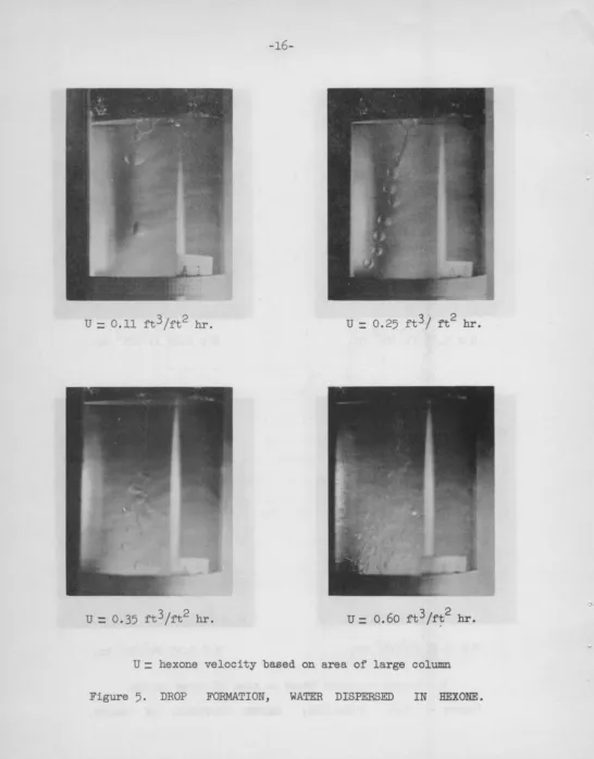
size become more irregular. Figures 4 and 5 are photographs of the
drops forming in the small column with a single hole plate. The upper
left hand photograph is the lowest flow rate, while the lower right
photograph is the highest flow rates. Coalescence began in the column
as flow increased. At high flow rates, the fluid from the plate issued
in a variety of sizes, a greater percentage of drops were smaller than
those formed at the low flow rates.
The rate at which the fluid was going through the hole was a
function of the presDure drop across the plate, as in an orifice. On
the small column, the drop formation and drop size in ranges of
trans-ition was visually observed and the pressure drop across the plate and
the dispersed rate were recorded. Several of these points ·were recorded
and plotted in Figures 6 and 7. The visual observations and pressure
drop points were reproducible to approximately 15%. The pressure drop
across the plate was obtained in the large column, and when used in
conjunction with Figures
t
or 7, the type of drops in the large columncould be predicted.
Large Column
The experimental work on the large column was divided into two
phases: water dispersed in hexone and hexane dispersed in water. In
each phase of the work, plates A, B, C, and D were used. The
temper-ature of the liquids averaged 270 C. with a 2° C. deviation. There
was no noticeable effect of temperature on holdup. The tempertures
were recorded at the supply barrels.
At low flow rates and low holdup, the drops in the column were
sharply defined. As the flovJ rates and holdup increased, the crowding
of the drops in the column became greater, until at high holdup, the
drops, when observed under strong illumination, appeared to be going
3 2
U
=
0.15 ft /ft hr. U=
0.22 rt3 /rt2 hr.U
=
0.45 ft3 /ft2 hr. [image:17.570.9.557.19.716.2]U
=
hexane velocity based on area of large column3;
2U
=
O.ll ft ft hr. U=
0.25 ft3;
ft 2 hr. [image:18.564.8.554.13.711.2]U= hexane velocity based on area of large column
.LO
.8
.6
« ,4
1&.1
...
;
Ill .2
1&.1
:I:
u
z
- .I A. .08
0 ~ .06
~ .04
~
Ill Ill
f
,02,01
---
-
-17-EV
·-
~
-
r-:1:
c
i
~0
l
A/
Ju
-·
I
I
.o1 .oz .o4 .06 .oe .1 .2 .4 .s .e 1.0
HEXONE RATE FT3/FT2HR HOLE
A. CONE STARTING
B. CONE I" LONG
c. START OF COALESCENCE
D. MANY SNALL DROPS IN COLUMN
E. LARGE HOLDUP, LARGE VARIATION
OF DROP SIZE
[image:19.571.10.552.19.702.2]HEXONE RATE BASED ON AREA OF LARGE COLUMN
10 90 6.0
a: 4.0
"'
...
<(· ~ ' ' 2.0
en
"'
:1:
~
- 1.0
A. .8
~ .e 0
~ .4
~
en en
"'
~ .2.I
-18-i
! i
~
v
lo CJ'
1
/
'
c'l
uv
/ 0
p
b(
.01 .02 .04 .06 .08.1 .2 .~ .6 .B LO WATER RATE FT3tn2HR HOLE
A. CONE STARTING
B. CONE 114" LONO
C. START OF COALEICENCE
D. MANY SMALL DROPS IN COLUMN
E. LAIItH HOLDUP, LARGE VARIATION OF DROP IIZI
WATER RATE BASED ON AREA OF LARGE COLUMN
Water dispersed in hexone
The water (dispersed) rates in this part of the study varied between lC ft. 3/ft.2 of column area-hr. to 130 ft.3/ft.2 hr. The hexone (continuous) rates used were 0,
25,
53, 100, and 155 ft.3j.2hr.With the nozzle plate A (the 22 1/16 inch hole plate) the holdup increased rapidly with increasing water rate at a constant hexone rate (Figures 8, 9, 10, 11 12). The holdup increased to a certain point and then leveled off and continued to remain almost a constant value with increased water rates. Run A-11-S (Figure 12) shows particularly well that the leveling off was an abrupt change. The point in the curve of holdup versus water rate at which the leveling off occurred was termed the "break" point. The holdup at rates belov1 the break point was repro-ducible. It was visually observed that below the break point, the drop sizes· in the column became progre-ssively smaller as the water rate increased and there was little tendency to coalesce. After the break point, coalescence became quite noticeable with some drops approaching one half inch in their longest axis. These drops were a milky white, which indicated an emulsion of hexane in water. •
The water phase leaving the column all during the operation of
plate A was an emulsion of hexone in water. The amount of hexone carried out with the water phase was much greater after the break point,
4%
hexane by volume just prior to the break point to 36% shortly after the break point. Carryover of water out with the hexane phase was less than 1/2% by volume past the break point, and less at lower dispersed rates. The emulsification of hexone and water is believed to be a function of the liquid system used and not of the column. It was noted that in the small column, hexone emulsified with a hydrochloric acid solution of water quite readily, while an emulsion of water and hexone was never observed in the small colmmn.
The increase in holdup with water rate was not as rapid with plate B, 89 1/16 inch holes, as with plate A (Figures 8, 9, 10, 11, 12) Equal drop size was gotten for greater water rates than with p:iba.te A·. From the Figures 8, 9, 10, 11,12, it is seen that a similar break point
occurred in the curve. The dispersed rate at which the break point occurred with plate B is approximately twice that as with plate A. Increasing continuous rates decreased the holdup and the dispersed rate at which the break point occurrPd. Similar carryover of hexone with the water phases occurred past the break point. At low flow rates and low holdup, there was no carryover of hexane. An attempt was made to photograph the drops to determine drop size as Grandjean (5) did. •At medium and high holdup the drops were so close together that a s!~rp
definition of a drop could not be distinguished. Therefore, the
photo-graphs were abandoned.
.,.
A.;;)
Q
...J
0
2;
40
. 35
30
2!5
20
15
•
tO
0 o~~~~~~--~--~~--5~o~~.~o~~7~o~~~~o--~9~o~~,~oo~~,~,o~~,t~o~-=,,~~~-,~4G
WATER RATE FM~HR
FIGURE 8. HOLDUP VS. WATER RATE, HE XONE RATE 0 FT31f12HR •. WATER DiSPERSED
[image:22.562.16.545.13.705.2]40 r---~---~---~---~~---~---~---~
30 ~---+---r---+---~~--+----+---4---~
25
A.
i
zo ~---+---~~~+---+---~~---+---~---~..J 0 %
15
10
5 .
0
0 IC' 20 30 .. 0 50 60 70 80 90 100 itO 120 130 140
WATU ltAT! F-r3tft2HR
CL :>
Q
_,
Q~
40
r---~---~---r---~---~---T---as
15
10
s
0 o~~~~~--2~o--~a~o--~4~o--~oo--~so~--~7~o---e~o~--~.o~--,o~o----~~~--~--~~40
WtllWR FIATf FT3/H2ttft
4-0
35
30 - - --··-·
e
25
••
~ :l 0 20
.J
0
-..:
15
40
!5
30
Z5
'#
L
zo
::;:) Q ..1 0
%
15
10
5
0
0 <tO
fiGURl12.HOLDUP VI. WATER
2 2 uus• 01. n
ee Iliff' OLES
357 111• OLU
I t 1/5 HOLtS
!5C 6(.) 70 10 90 100 110 120 150 140
WATER RATE FT3/FT2HR
No break point was observed with plate C, 357 1/16 inch holes. The drop size produced was quite uniform up to about 35 ft.3/ft.2hr. of water rate; at higher dispersed rates there was a variation in the drop size. There was little or no carryover of the hexone with the water phase noted. The drops formed by plate C were larger than either
of those formed by • or B. These large drops fell more rapidly and therefore the holdup obtained with plate C was less than with either
A or B.
The relation between pressure drop and flow rate is shown in Figure 13 for water dispersed in hexane for plates A, B, and C. Drop size and pressure drop relationships predicted from Figure 7 and Figure 13 were confirmed by visual observation. Increased pressure drop produced smaller drops, and a tendency to coalesce. The use of
these figures, however, are limited to the region before the break point.
Reference to Figures 8, 9, 10, 11, 12 will show that plate D,
89 1/32 inch holes, follows practically the same curve as plate A. Plates A and D have the same hole area. For the same water rate, the holdup of plate A is slighly greater. Therefore, the drops formed by plate D are a little larger and more uniform than those formed by
plate A. The amount of carryover of hexane in the water phase and the
visual observations of both plates were approximately the same.
Hexane dispersed in water
The hexane (dis2ersed) rates in this study varied between lOft?
/ft.2hr. and 90 ft.J/ft.2hr. The water (continuous) rates used were 25, 75, and 125 ft.3/ft. 2hr.
With plate A the holdup increased rapidly with increasing
dis-persed rates (Figures 143 15, 16). With the hexane dispersed, there
was no definite break point observed as when the water was dispersed.
There was, however, a leveling off of holdup with increasing dispersed rates. With increased continuous rates, the holdup at which this
leveling off occurred became less. There was a little carryover of
hexane with the water phase. A maximum of 6% by volume was observed
at the highest rates. As the holdup increased there became an interface visible in the conical section between the region of holdup and tro
water phase lea,ving the bottom of the colunm. As the water ratP
110
60
40 20 a:
1&.1 10
.... c
!<. ~
1/) 6. 1&1
:z:
() 4. ~ IL 0 2. a: 0 1&1 a: ;:) I. Ill Ill .8
"'
a:A. .6
,4
.2
,I
~--4--
···-~--+---1---
.-t
I I ! 1---l--! ---· I! I
! I
i
· - · - -
---·---·
--·--·-1- - - -·
·-
---'
- -· -
-0 PL T A 22 1116 HOL S
e PL T 8 19 1116 HOL S
s IPL T c 3!5 1/18 HO ES
,01 • 02 . 04 .06 .08 ,10 .2 .4 .6 ,8 1.0 2 . 4. 6. 1.10 •
WATER RAT! FT5tFT2HR HOL!
[image:28.568.10.556.21.728.2]~
A.
::l
0 ~
0
%:
40
3!5
so
Zl
zo
II
10
I
0
II 1/168 HOLII 111111• OLll
UTI OL£1
18 1/3 HOLI8
0 o~~~--~--~~~0~~~--~--~--~~~~o~--~--~--~~~~--J
4 60 60 70 80 9 140
HE XON£ RATE F -,3 /Fr2 HR
40r---~---r---~---~---~---~---~
~
~ 20 ~---~---~~---~---~~---4---+---~
~
z10
0PL.AT A 22 1111• HOLES
9PLAT 8 IJ8 Vl6• OLE:S
$PLAT C 3!571111• ES
OPL.AT D I t 1/31 OLE$
40 50 10 70 10 90 100
HEXONE lUTE FT'5/FT2H"
110 120 1'50
FIOUJIE IIS,HOLDUP vs. HEXON[ "ATE, WATER RATE 75 ,TJ/fTZHR, HEXONE DIIKRIED
40~---~---~---~---~---~---~---0PLAT A 2 2 1/1 .. ePLA B I t Ill
~PLAT C 071/ LllS
0 PLA D I t 1/11 HOLlE S
00 10 20 30 40 50 10 70 80 90 100 110 120 130
140
H!XONf RATE FT31FT2HR
Considerable foaming occurred at the interface of the water and
hexone at the top end box, and i f the interface got too near the top
exit, there was some carryover of water with the hexone phase. If the
interface was kept three or four inches from the top of the end section9
there was no carryover of water.
Quite uniform drops were obtained with plate B when the hexone was
dispersed. At high flow rates the drop size began to deviate a little.
At not time was there any indication of carryover of either phase out
the ends of the column. From Figures
14, 15,
and16
it is seen that asthe continuous rate increased the holdup increased.
With plate
c,
the drops were quite uniform over the whole rangeinvestigated. There was no appearance of coalescence even at the high
flow rates. Increased continuous rates increased the holdup slightly
for the same dispersed rate.
With all the plates visual observation again demonstrated the
relationship between the pressure drop and drop formation and size as
predicted from Figures 6 and 17.
The performance of plate
D
was quite similar to that of plate AoFigures
14, 15,
and16
show that the curves of each overlap each otherin various regions of flow. There was approximately the same amount of
carryover for both plates. It was noted that the amount of hexonr
carried out with the water phase increased with the water rateso
DISCUSSION
In a cqlumn of liquid, a large drop of a second liquid will rise or
fall more rapidly than a small drop of the second liquid, since the
frictional forces on a small drop are greater than those on a la~ge dropo
T~erefore, if all the drops in a spray column were the same size; they
would rise or fall at the same velocity, providing they travel in a
straight line. The velocity of the drops haR been expressed as follows
(1):
U
=
100 Fd--r
(A)where U is the actual linear velocity of the drops in ft./hr., Fd is
the dispersed rate in ft. 3/ft.2hr., and f is the percentage holdup.
U should be independent of the dispersed phase rate if the drop size
at the nozzle is constant (l)o It can be shown that for a constant
velocity of the drops, the plot of holdup yersus dispersed rate at a
80 -- -- ····-t--f- --- -··· --- t---
t-I
60 . -.. ---
--40
t
--I
Ij
l
20
!
i
-tr
10 --- -. .,....-. - - f- -I -
r-1&1
....
<( e. ~
~ I
1/) 6. I
~I
IIJ I
:r
..
.
W
- ----c.;.
I I ~
;
I
/ I I
a.
:
I i::> 2. -+---
-a: !
0
r4
.
.
a
IIJ
a:
-
t
::;:) 1.0 ~-- f-·- -- --
-1/)
-
t--1/) .8
c. --
-r--
· -
:
_.
f--- --
--
r-iE .6 ----· . - . -- ·
-c..
~- I
,4
--
~- . ---.. --+--- - f l- + ----q" !
~ ' I
~ ~
I
1--- - - -. ··--... .
.
.
tt"" ~-• •• 1' •-
~~:
.:t' 0 PLtAT~ A :u 1116 110 ES
& s
I
I 9 PLATf 8 19 1/16 HO ES ~ jP'.~T~ 0 35 16 HO ESI
,01 .02 .~ .06 .08.10 .2 _4 .6 . 8 1.0 z. 4. 6 • 8.10 tiEXONC 1\•TE F T3/FT2HR HOLE
[image:33.570.10.557.22.704.2]Inspection of Figures 14, 15, 16, show that the straight line relationship was found experimentally only in a short range for nozzle plate B, and a larger range for nozzle plate
c.
The deviation from the straight line is explained by the appearance of a variation of drop sizes. The smaller the drops, the less the velocity, and the tendency towards higher holdup. Examination of equation (A) shows that drop velocity is inversely proportional to the holdup. Thus, the holdup atlcrvv velocities ( as in the case of small drops) is larger than the holdup at high velocities with large drops. It must be remembered that the velocity in equation (A) is the average velocity of the drops if there is a variation of drop sizes in the column.
At moderate and high dispersed rates the drops from plate A break
away in uneven sizes from a cone of fluid at the plate and progress up
(or down) the column. Since there are many small drops formed, high
holdup is reached at much lower dispersed rates than with plate C. At
the break point, coalescence occurs and even though the throughput is
greater, the holdup remains the same.
A comparison of the curves (Figures 14, 15, 16) shows that a higher holdup is observed for a given dispersed rate with plate A than plate
c.
Therefore, the average velocity is lower with plate A, and hence a single
drop is in the column a longer time. This coupled with the fact that smaller drops provide a larger surface area per unit volume makes plate
A attractive to use in extraction. However, Joh~son and Bliss (7) found that a noezle plate with a greater number of holesgave better extraction rates for a given dispersed rate when acetic ~~id was being extracted from water by hexane.
Figures 14, 15, 16 show that the effect of thehole diameter on holdup is quite great, if the number of holes is constant as in plates
B and D. If the tota 1 hole area is constant, as in plates A and D, there is little difference in performance. Use of plates A, D, and, in some cases B is dependent on the emulsion characteristics of the liquid systems used. This study has sh'Jwn that as the number of holes is increased, some undersirable emulsifying characteristics may be avoided.
The literature (1, 2) recommends that the phase with the greatest
flow rate be the dispersed phase. Appel and Elgin (1) used the system toluene-benzoic acid-water and indicated that the extraction coefficient
was greater if toluene was dispersed when the flow rat::i o of toluene
to water was appreci~blw greater than unity, and was greater with water dispersed if this ratio was considerably below unity. Whenever one flow rate was considerably in excess of the other, the dispersal resulted
in greater interfacial area, which was confirmed in this investigation.
Figure 18 is a cross plot of the holdup versus flow rate curves for plate C. If the ratio of water rate to hexone is greater than unity,
2.5
0 2.0
0
"'
"'
(/) (/) a:a:
"'
"'
A.~
(/)0 1.~
0
"'
a: z
"'
0 .... )(c
"'
):%:
zz 1.0
"' "'
:s:%:):~
A. A.
:;) :;) 0 0
~ ~ ,5 oo
%:%:
0
/
v
0 .5
v
/
/
/
1,0 1.5
WATER RATE HEXONE qATE
/
v
/
2.0 2.5
[image:35.570.7.556.28.704.2]the ratio of holdup when water is dispersed to holdup when hexane is
dispersed is greater than unity. Therefore, the holdup when water is
dispersed is greater when hexane is dispersed. Greater holdup indicates
more interfacial area and greater time of contact between the phases. This analysis is based on holdup; other factors such as relative solub-ilities and diffusivities should also be considered in determining which phase should be dispersed. Johnson and Bliss (4) .found that the phase receiving the solute should be dispersed when extraction of acetic acid from water by hexone is being carried out.
Elgin and Blanding (3) observed a phenomena which was called "flooding." This was a point where, as the flow rates were increased, there was an abrupt transition in the holdup to about double its
immediate previous value. This was accompanied by the slow movement up the column (when the light phase was dispersed) of a second interface
between two regions of hold~p. This interface could not be made to remain stationary. No such effects were observed in this study. At high holdups the column was so packed with drops that the appearance of such an interface would have been difficult to detect. At no time was there an abrupt doubling of the holdup with a small change in the flow rates.
The usual definition of flooding is that point at which one phase is carried out the column with the second phase. Periodic checks were made on the point where this tne of flooding occurred and it was in no way reproducible. This point was, therfore, not determined in this
study, because it is believed that this phenomena is a characteristic of the liquid system used and not of the column.
A mathematical correlation of a modified Reynolds number and friction factor, as Grandjean (5) used was attempted. Since the drop
size was no known, the diameter of the holes was used to make the
-35-CONCLUSIONS i'~ND RECO\JTI',1EI\Jl\.TIONS
Conclusions
l . A nozzle plate was designed for use in a spray column when the
dispersed phase tends to wet the surface of the plate. This
plate formed satisfactory drops and no wetting of the plate was
observed.
2. The use of a small number of holes in a nozzle plate tenas to
produce small drops and high holdup for low dispersed rates.
Use of a larger number of holes in the plate produced larger
and more equal drop size. Emulsions were practically non-existent
with a large number of holes. Emulsions and carryover were
encountered with a small number of holes, with the system
hexane-water.
3.
The effect of size of holes on holdup was quite noticeable if thenumber of holes in a plate was constant. In the two cases
invest-igated, there was little effect of size of holes on holdup if the
total hole area remained constant.
4.
It is possible to predict qualitatively drop size distributionin a large column from the pressure drop across the nozzle plate.
Recommendations
1. Both end sections of the large column should be enlarged to
facilitate easier control of the interface and to effect better
separation of the phases.
2. Additional work should be done on other liquid systems to
ascertain whether the f ;ndings of this investigation are general.
J. Liquid-liquid extraction should be carried out in the column to
determine the effect of the number of holes and hole size on
LITERATURE CITED
l . Appel, F. J. and Elgin, J. D. Industri~l and Engineering Chemistry.
~ 451 (1937).
2. Elgin, J. C. United States Patent 2,364,892. Dec. 12, 1944.
3.
4.
Elgin, J. C. and Blanding, F. H.
Institute of Chemical Engineers.
Elgin, J. C. and Browning, F. 1i.
Institute of Chemical Engineers.
Transaction of the American
38, 305 (1942).
Transactions of the American
31_ 639 (1935).
5. Grandjean, Vi. B. Unpublished M.
s.
Thesis, Iowa State College. (1949).6. Hunter, T. G. and Nash, A. W. Industrial Chemist. 2_, 245, 263,
313 (1933).
7. Johnson, H. F. and Bliss, H. Transactions of the American
Institute of Chemical Engineers. 42, 331 (1946).
8. Row, S. B., Koffolt, J. H. and Withrow, J. R. Transactions of
the American Institute of Chemical Engineers. 37, 559 (1941).
Appreciation is expressed to Professor G. L. Bridger, Head,
Chemical Engineering Department, Iowa State College, Ames, Iav1a, for
his helpful advice and suggestions with the conduct and plan of this
investigation, and for his aid in preparing this manuscript.
Acknowledgment is due to Professor B. F. Ruth of the same
depart-ment and institution for his interest and encouragement in the conduct
of this investigation.
Final acknowledgment is made to the Ames La bora tory of the Atomic
Energy Commission for underwriting the expense and for providing
Run
A 10 1
A 10 2
A 10
3
A 10 4 A 10 5
A 10 6
A 10 7 A 10 8
· A 10 9
A 10 10
A 10 11
A 10 12
A 10 13
A 10 14
A 10 15
A 10 16
A 10 17
A 10 18
A 10 19
A 10 20
A 10 21
A 10 22
A 10
23
A 10 24
A 10 25
A 10 26
A 10 27
A 10 28
A 10 29
A 10
30
A 10 31
APPENDICFB
APPENDIX A
Water Dispersed in Hexone
Summary of Results
Cont. rate ft) /ft .2hr.
Plate A
0 0 0 0 0 0 0 25 25 25 25 25 25 25
53
53
53
53
53
53
53
100 100 100 100 100 100 100 155 155 155Dis)ersed rate ft. /ft.2hr.
22 1/16 holes
10.0 20.0 27.5
35.5
44.0 50.0 73.5 9.8 20.0 27.5. 35.2 43.2 49.3 66.5 10.0 20.027.3
Appendix A (continued)
Cont. rate Dis~ersed rate Holdup
Run
ft.3 /ft.2hr. ft. /ft.2 hr.%
Plate A 22 1/16 holes (cont.)
A 10 32 155 35.2 17.7
A 10 33 155 43.5 18.4
A 10 34 155 50.0 18.7
A 10 35 155 68.0 19.2
A 10 S 1 53 10.6 1.03
. A 10 S 2 53 30.4 7.20
A 10 S 3 53 32.4 8.75
A 10 S 4 53 35.6 11.0
A 10 S 5 53 17.h 12.3
A 10 S 6 53 40.1 14.7
A 10 S 7 53 42.5 18.2
A 10 S 8 53 45.0 20.6
A 10 S 9 53 47.5 23.9
A 10 S 10 53 51.2 22.7
A 10 S 11 53 56.0 22.8
A 10 S 12 53 67
.o
23.0AilS 1 155 49.4 19.7
A 11 S 2 155 32.6 17.7
A 11 S 3 155 34.5 17.6
A 11 S 4 155 36.4 17.8
A 11 S 5 155 38.7 18.0
A 11 S 6 155 40.2 18.1
A 11 S 7 155 42.5 18.2
A 11 S 8 155 44-7 18 .. 5
A 11 S 9 155 27.3 9.35
A 11 S 10 155 29.4 12.6
A 11 S 11 155 32.6 17.2
A 11 S 12 155 45.5 18.4
A 11 S 13 155 50.9 19.2
A 22 1 0 9.30 2.33
A 22 2 0 19.0 4.66
A 22 5 0 43.6 20.7
A 22 6 0 47.8 23.8
A 22 7 0 59.0 24.0
Appendix A (continued)
Cont. rate Dis5ersed rate Holdup
Run ft.3/rt.2 hr. ft. /ft.2 hr.
%
A 22 11 155 13.5 2.74
A 22 12 155 28.4 12.0
A 22 13 155 31.0 16.3
A 22 14 155 37.9 17.9
A 22 15 155 48.0 18.5
A 22 16 155 59.0 19.0
A 22 17 155 72.0 20.3
A 22 18 155 94.0 19.9
A 31 2 0 29.4 7.34
A 31
3
0 49.6 26.5A 31 4 0 52.2 26.1
A 31 5 0 69.6 28.0
A 31 8 25 45.0 20.5
Plate B
89
1/16 holesA 1 1 0 9.7 1.18
A 1 2 0 20.0 • 2.26
A 1
3
0 35.2 3.74A 1 4 0 50.0 5-95
A l 5 0 62.5 8.80
A 1 6 0 75.6 13.0
A 1 7 25 10.0 1.15
A 1 8 25 20.0 1.98
A 1 9 25 35.2 3.20
A 1 10 25 50.0 5.56
A 1 11 25 62.5 8.80
A 1 12 25 76.0 13.45
A 1 13
53
10.6 0.76A 1 14 53 20.2 1.53
A 1 15
53
35.0
2.52A 1 16 53 49.0 4.65
A 1 17
53
62.5 7.80A 1 18 53 76.0 12.80
A 1 19 100 10.0 1.15
A 1 20 100 20.2 1.87
A 1 21 100 35.2 3.17
A 1 22 100 50.0 6.00
A 1 23 100 62.5 10.7
1,
~~---Appendix A (continued)
Cont. rate Dis3erseg rate Holdup
Run ft.3 /ft.2 hr. ft. /ft. hr • .
%
A 1 24 100 75.8 16.6
A 1 25 155 10.2 0.76
/I 1 26 155 10.2 0.69
....
A 1 27 155 20.0 1.80
A 1 28 155 35.5 3.20
A 1 29 155 50.0 6.22
A 1 30 155 ' 62.5 13.85
A 1 31 155 77.0 23.6
A 2 1 0 10.0 0.88
.
A 2 2 0 20.4 1.80
A 2 3 0 35.2 2.98
A 2 4 0 50.0 5.26
A 2 5 0 76.0 13.3
A 2 6 25 10.0 1.11
A 2 7 25 21.0 2.14
A 2 8 25 35.6 3.66
A 2 9 25 50.0 6.60
A 2 10 25 76.0 16.3
A 2 11 53 10.0 0.76
A 2 12 53 21.2 1.60
A 2 13. 53 35.2 2.98
A 2 14 53 51.0 6.10
A 2 15 53 74.0 15.5
A 2 16 100 9.7 0.96
A 2 17 100 20.0 1.91
A 2 18 100 35.5 3.44
A 2 19 100 49.0 5.91
A 2 20 100 75.8 16.2
A 2 21 155 10.2 1.11
A 2 22 155 20.8 2.22
A 2 23 155 35.5 3.58
A 224 155 51.0 7.66
A 2 25 155 76.0 24.5
A 2113 155 28.0 1.83
A 21 14 155 36.0 2.66
A 21 16 155 47.7 6.56
A 21 17 155 53.5 8.25
Appendix A (continued)
Conj• ra~e Dis~ersed rate Holdup
Run
ft. /ft. hr. ft. /ft.2hr.%
A 21 19 155 63.6 12.4
A 21 20 155 83.0 25.7
A 21 21 155 45.5 4.96
A 21 22 155 41.3 3•62
A 21 23 155 70.0 . 17.3
A 30 2 0 88.6 19.6
A 30 4 0 91.0 21.0
A 30 7 25 98.5 25.5
A 30 8 25 123.0 27.0
A 30 9 53 73.0 16.8
A 30 10 53 95.5 31.2
A 30 11 53 108.0 33.7
A 30 12 53 123.0 33.9
A 30 13 100 71.6 17.3
A 30 14 100 85.0 23.0
A 30 15 100 104.0 26.1
A 30 16 100 123.0 26.3
A 30 17 155 76.5 22.4
A 30 18 155 95.5 20.6
A 30 19 155 112.0 21.3
A 30 20 155 123.0 21.0
A 30 21 0 76.0 13.1
A 30 22 0 106.0 34.1
A 30 24 0 120.0 40.1
A 30 25 25 78.0 18.7
A 30 26 25 91.0 31.4
A 30 27 25 112.0 35.0
A 30 28 25 96.5 32.1
A 30 29 25 126.0 33.6
A 30 31 53 91.0 32.0
A 30 32 53 112.0 30.2
A 30 33 100 76.5 23.1
A 30 34 100 91.0 28.8
A 30 35 100 102.0 26.0
A 30 36 100- 127.0 27.2
A 30 37 100 85.8 27.2
A 30 39 155 76.0 25.1
A 30 40. . 155. 80.5 23.8
· Appendix A. (continued)
Cont. ra~e tJis~rsed rate Holdup
Run
ft.3/ft. hr. ft. /ft.2 hr.%
Plate C 357 1/16 holes
A 26 1 155 15.8" 2.02
A 26 2 155 34.3 4.00
A 26 3 155 44.5 4.96
A 26 4 155 59.0 6.50
A 26 5 155 72.0 8.05 .
A 26 6 155 93.0 14.2
A 26 7 155 114.0 16.4
A 26 8 155 . 125.0 24.0
A 26 9 100 14.4 1.38
A 26 10 100 21.6 2.33
A 26 11 100 31.8 3.40
A 26 12 100 41.7 4-54
A 26 13 100 55.0 5.80
A 26 14 100 77.0 7.90
A 26 15 100 102.0 13.8
A 26 16 100 129.0 19.4
A 26 17 53 12.5 0.23
A 26 18 53 28.8 1.38
A 26 19 53 49.2 3.75
A 26 20 53 62.5 5.24
A 26 21 53 72.0 6.21
A 26 22 53 83.5 8.14
A 26 23 53 106.0 11.8
A 26 24 53 125.0 16.0
A 26 25 25 14.0 1.26
A 26 26 25 30.3 3.44 .
A 26 27 25 48.1 4.96
A 26 28 25 64.0 6.40
A 26 29 25 81.5 8.30 ..::..
A 26 30 25 93.0 9.80
A 26 31 25 111.0 12.8
A 26 32 25 129.0 16.0
A 26 33 0 14.4 0.88
A 26 34 0 33.0 2.68
A 26 35 0 52.4 4-55
A 26 36 0 72.7 5.90
Append
i
x A
(c
on
ti
n
ued)
Co
n
j· rate
DisJerseg rate
Holdup
Run
ft. /ft.2
h
r.
ft. /ft.
h
r.
%
A
26 37
0
8
5.0
7.70
A
'2
6
38
0
106.0
12.1
A
2
6
39
0
132.0
15.5
A
2
6
40
0
13.3
0.61
A
2
6
41
0
2
8
.0
1.72
A
26 42
0
4
9
.7
3.40
A
2
6
43
0
68.0
5.15
A
26 44
0
106.0
11.2
A
2
6
4
5
0
39.8
2.41
A
26 46
0
60.0
4.16
A
26 47
53
14.8
1.72
A
26 48
53
31.6
3.78
A
26 49
53
39.8
4-31
A
26 50
53
49.4
5
'
.40
A
26 51
53
61.9
7.04
A
2
6
52
53
130.0
18.3
A
25 1
0
10.6
0.38
A
25 2
0
19.9
0.88
A
25 3
0
2
6
.
8
1.18
A
25 4
0
36.4
1.95
A
25 5
·
0
43.5
2.18
A
2
5
6
0
59.0
2.86
A
25 7
0
73.5
5.15
A
25 8
·
0
91.0
7.90
A
25 9
0
121.0
12.2
A
25 10
0
134.0
16.0
A
2
5
11
25
11.0
1.34
1-1.
25 12
25
20.
8
2.14
11.
25 13
25
27.6
2.71
A
25 14
25
36.2
3.28
A
25 15
25
44-4
3.97
A
25 16
25
52.
8
4.40
11.
25 17
25
72.0
5.92
A
25 1
8
25
89.0
8.6o
A
25 19
25
n2.o
ll.5
A
25 20
25
130.0
14.0
A
25 21
53
10.0
1.15
Cont. rate
Dis~ersedrate
Holdup
Run
ft.3/ft.2 hr.
ft. /ft.2 hr.
%
A 25 23
53
27.3
2.98
A
25 24
53
36.4
4.10
A 25 25
53
44.0
4.70
A 25 26
53
54.0
5.
6
5
A 25 27
53
77.5
7.83
A 25 28
53
93.0
10.4
A 25 29
53
10
8
.0
13.2
A 25 30
53
130.0
17.3
A 25 31
100
11.6
0.95
A 25 32
100
19.9
1.
8
3
A 25
33100
27.3
2.60
A 25 34
.
'
100
35.3
3.20
A 25 35
100
43.5
4.12
A 25 36
100
53.0
5.15
A 25 37
.
100
77.5
8.05
A 25
38
100
89.0
.
10.3
A 25 39
100
112.0
14.4
A 25 40
100
130.0
18.3
A 25 41
155
10.8
1.37
A 25 42
155
20.1
2.25
A 25 43
155
2
8
.4
3.02
A 25
44155
45.5
4.80
A 25 45
155
53.5
6.00
A 25 46
155
74.0
8
.45
A 25 47
155
89.0
12.0
A 25 48
155
114.0
17.6
A 25 49
155
130.0
25.5
A 32 1
25
46.5
4·75
A 32 2
25
75.5
8.15
A 32 3
25
110.0
13.7
A 32 4
25
129.0
16.5
A 32 5
53
12.8
l.64
A
32
653
31.0
3-44
A 32 7
53
51.0
5.95
A
32 8
53
74.0
8.55
A 32 9
53
104.0
13.5
Ap:p:!ndix A (continued)
Cont. rate
Dis~rsedrate
Holdup
Run
ft.3/rt.2 hr.
ft. /ft.2 hr.
%
Plate D 89 1/32 holes
A 6 1
0
10.0
1.30
A 6 2
0
20.2
2.64
A 6 3
0
27.3
4.13
A 6 4
0
35.3
7.24
A 6 5
0
44.0
11.6
A 6 6
0
50.0
15.?
A 6
'
7
0
72.0
25.8
A 6 8
25
10.0
1.61
A 6 9
25
19.8
2.68
A
6 10
25
'Zl.O4.44
A 6 11
25
35.3
7.71
A
6 12
25
43.0
11.9
A 6 13
25
50.0
'
17.9
A
6 14
25
72.0
25.1
A
6 15
53
10.0
1.3.8
A
6 16
53
'20.3
2.49
A
6 17
53
27.3
4.25
A
6 18
53
35.6
8.13
A
6 19
53
43.0
13.5
A
6 20
53
50.0
18.5
A
6 21
53
73.0
23.4
A
6 22
100
10.0
1.49
A
6 23
100
20.0
2.79
A
6 24
100
27.3
4.60
A
6 25
100
38.5
15.0
A 6 26
100
44.0
20.8
A
6 27
100
50.0
22.6
A 6 28
100
73.0
23.4
A
6 29
155
10.0
1.30
A
6 30
155
20.1
2.79
A 6 31
'
155
27.5
5.85
A
6 32
155
35.2
14.1
A
6 33
155
43.5
18.7
A
6 34
155
50.0
19.6
App:mdix A (continued)
Cont. rate
Dis~ersedrate
Holdup
Run
ft.3/ft.2
.
hr.
ft. /ft.2 hr.
%
A
5 1
0
.
10.0
1.68
A 5 2
0
20.4
2.91
A 5
3
0
35.2
7.24
A 5 4
0
50.0
16.7
A
5 5
0
66.0
26.5
A 5 6
0
78.0
26.9
A 5 7
25
10.0
1.53
A 5 8
25
20.0
2.79
A
5 9
25
35.2
7.61
A
5 10
25
49.0
18.4
A 5 11
25
62.5
24.5
A 5 12
25
72.0
25.2
A 5 13
53
10.0
1.53
A 5 14
53
19.8
2.52
A 5 14
53
35.3
7.54
A 5 16
53
51.0
19.5
A 5 17
53
62.0
23.2
A 5 18
53
74.0
24.7
A
5 19
100
10.0
1.65
A 5 20
100
20.0
3.25
A
5 21
100
35.4
13.8
A 5 22
100
50.0
23.0
A 5 23
100
62.0
24.1
A
5 24
100
73.0
25.2
l~
5 25
155
10.0
1.95
A 5 26
155
19.8
3.52
A 5 27
155
3
5
.2
16.5
A