International Journal of Innovative Technology and Exploring Engineering (IJITEE) ISSN: 2278-3075,Volume-8 Issue-11, September 2019
Abstract: Complexity is the major issue in the development of pipelined Fast Fourier Transform (FFT) structure. A novel parallel pipelined FFT design constructed for low complexity and Latency. The proposed structure efficiently uses pipeline and parallel pipeline in the design. The first three stages of the structure follow the pipelining and from fourth stage there are two parallel paths simultaneously compute four complex additions, the first three single path stages that reduces complexity, parallel pipeline stages at the end of structure also reduces the Latency. The proposed structure is an optimized solution to reduce the trade-off between Latency and complexity. The comparative performance of the proposed structure with several other existing structures shows that it has Low latency with small cost of hardware.
Index Terms: complexity, FFT, parallelism, pipelined
I. INTRODUCTION
Major transformations in signal processing, image processing and other communication applications are possible because of the advancements in FFT. Pipelined FFT are very important and efficient architectures in the VLSI implementation of FFT. Discrete Fourier transform is defined with exponential kernel function in (1)
1
0
[ ]
[ ]
N
kn N n
F k
f n w
(1)Where
2
j kn
kn N
N
w
e
Cooley and Tukey [1] who behind the invention of FFT ,the efficient transformation to enumerate DFT in an operative way in 1965. Pipelined and parallel pipelined FFT structure proposed in[2] is the evolution in VLSI implementation of FFT. CORDIC iteration method proposed in[3] is organized method for implementation of FFT.
Pipelined FFT architectures for speech processing or applications are proposed in[4], FFT for EEG[5] is introduced, Split-Radix FFT for signal processing applications implemented in [6], low power variable length FFT proposed in[7]. Several pipelined and parallel pipelined architectures are proposed in the resent scenario [8],[9]. FFT design when inputs are is RFFT is introduced in [10]. Pipelined architecture for RFFT in [11] has an advantage of power and delay efficiency.
Revised Manuscript Received on September 02, 2019.
Prasanna Kumar G, Department of Electronics and Communication Engineering, JNTUK, Kakinada (A.P), India.
Krishna.B.T, Professor, Department of Electronics and Communication Engineering, JNTUK, Kakinada (A.P), India.
Pushpa Kotipalli, Professor, Department of Electronics and Communication Engineering, Shri Vishnu Engineering College for Women, Bhimavaram (A.P), India.
FPGA implementation of pipelined FFT architectures are proposed in [12]. several other parallel pipeline designs in recent years proposed in [13],[14],[15].
Here is a new pipelined parallel FFT architecture, where initial three stages follow pipelined structure and from fourth stage onwards it follows the parallel pipelined structure.A novel structure of pipelined Fast Fourier Transform is implemented for two radix structures those are radix-2 and radix-22.
The five sub sections of the paper as follows, Section I gives the introduction of the Pipelined architecture for Fast Fourier Transform. Also, several existing works in the recent years on FFT optimization are described in this section. Section II gives the detailed analysis of proposed structure with diagrammatical explanation, section III describes the sub module used in the proposed structure, and section IV elaborates comparative results. Practical observations are compared with traditional techniques and the conclusions of the proposed work are mentioned in section V.
II. PROPOSED ARCHITECTURE
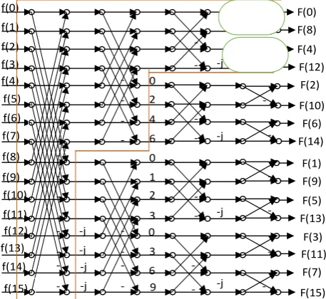
Radix-22 DIF Fast Fourier Transform architecture for 16
points illustrated in Figure 1, in which twiddle factor multipliers are required one time for two stages. The decomposition of Radix-22 is first F[k] decomposed as odd
and even segments F[2k] as well as F[2k+1] shown in equations (2) and (3). F[2k+1] further dived into even and odd parts according to equations (4) and (5) then the resultant twiddle factors are distributed as shown in Figure 1
1 2
2
0
[2 ]
[ ]
[
]
2
N
kn N n
N
F k
f n
f
n w
(2)
1 2
2
0
[2
1]
[ ]
[
]
2
N
n kn
N n
N
F k
f n
f n
w w
(3)
[ ]
2 1
4 4
[4 1]
4 0
3 4
N f n f n N
N n kn
F k f n w wN
n j
N f n
(4)
Two Parallel Pipelined FFT Architecture After
Third Stage for Low Complexity and Latency
1 4 3 4 0 [ ] 2 [4 3] 4 3 4 N n kn N n N
f n f n
N
F k f n w w
j N f n (5)
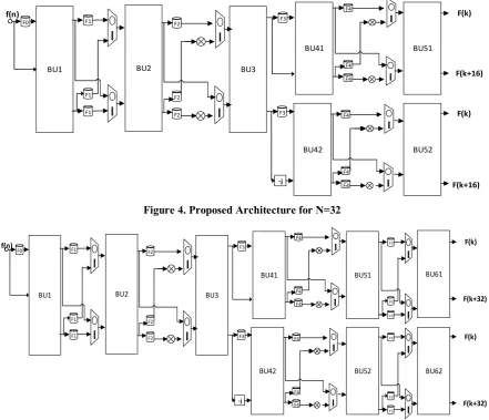
The proposed structure in FFT data flow illustrated in Figure 2, in which initial three parts are modeled on pipeline basis, from stage 4 onwards designed on pipeline parallel fashion shown as circles in stage 4 of Figure 2.
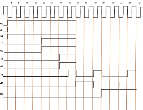
The proposed design for16 values are displayed in Figure 3, 16-point FFT requires four stages of butterfly units. The structure follows the pattern as, stage-1, stage- 2 and stage-3 are constructed with one butterfly unit which are BU1, BU2 and BU3 respectively. Stage-4 is constructed with two butterfly units BU41 and BU42.Each butterfly unit has two complex inputs and two complex outputs. This structure requires Intermediate elements between one stage to another stage, those are FIFO’s to store the intermediate values, multiplexers for selecting two-point butterfly in the overall sixteen-point butterfly unit. The data flow from left to right, at first the initial 8 samples of f(n) that is f(0) to f(7) stored in FIFO F0, the timing plot of the proposed design is displayed in Figure 6 which is control timing for inputs, MUX’s FIFO’s and multiplier coefficients, in stage-2 three FIFO’s F1 and two multiplexers with selection input 0 and 1 used. Stage 3 is like stage-2, in stage-4 there are two butterfly units and two FIFO’s for data processing.
Proposed architecture for N=32 is shown in Figure 4, in that there is one more additional parallel stage used to process the data coming from stage-4. The throughput of the proposed architecture is two. The proposed design for N=64 is shown in Figure 5The progression of information of the proposed structure is portrayed as, FIFO F0 loads data from f(0) to f(7) when the first eight clock pulses data is available and in 8pulse onwards control engages read r0 it scrutinizes initial info estimation of f(0) and opposite way moving information is f(7) before f(8), so f(8) as well as f(0) handled through butterfly structure which comprises of dual summation circuits and creates two yield esteems. These two dual summation circuits are put away in two different First-in First-out blocks. The selection lines of multiplexers S0, S1 is chosen based on butterfly structure. After eight clock cycles from 9 to 12 the multiplexer choice line S0 can be made logic 0 f(0) f(1) f(2) f(3) f(4) f(5) f(6) f(7) f(8) f(9) f(10) f11) f(12) f(13) f(14) f(15) -j -j -j -j 0 2 4 6 0 1 2 3 0 3 6 9 -j -j -j -j F(0) F(8) F(4) F(12) F(2) F(10) F(6) F(14) F(1) F(9) F(5) F(13) F(3) F(11) F(7) F(15)
-Figure 1: 16 point-FFT usingRadix-22 DIF
.
One end of the butterfly is composed in FIFO F1 and the other edge can be composed in FIFO F2. R1 is the read signals for both the FIFOs.
R1 enables the read operation in both the FIFOs. The information in initial FIFO is scrutinizes in the butterfly structure around then s1 signal logic zero chooses moving information prepared through next part of the butterfly creates two yield esteems put away in another two FIFO's. These two FIFOs are denoted as F3 and F4. FIFOs F3 and F4 are empowered by w2 for two clock pulses. Similarly, from 13 to 16 span, signal S0 logic level one indicates that the information in F2 is moved to FIFO unit F1 of stage-1.First butterfly stage can free up additional eight extra rooms. Maximum of four yields are possible in one clock pulse. During the sixteenth clock pulse butterfly five creates F (0), F (8). In the same way butterfly six produces F (2), F (10). Successive clock pulse creates a different four yield possibilities. Remaining eight yield possibilities, empower S1 ascertain. At that point the last eight points of initial stage butterfly handles with in comparative design starting at now showed up for getting another eight esteems, five clock cycles are required fit will takes further five clock pulses. The Latency for 16-point FFT is 9 and for 32 is 19 and of 39 for 64-point FFT. Regularly in an N point Fast Fourier Transform it is 5N/8-1. This procedure can be extended to higher order FFT structures also, Figure 4 shows the proposed FFT structure for N=32, which takes additional one stage that is two butterfly units. Figure 5 shows the proposed structure for N=64 in which there are one more additional stage. The subunits in the proposed architecture are Butterfly Unit (BU), multiplexers and twiddle factor multiplier unit. Each individual butterfly structure has two complex adders illustrated in Figure 7. Each real addition is performed by the carry save adder for low power
f(0) f(1) f(2) f(3) f(4) f(5) f(6) f(7) f(8) f(9) f(10) f(11) f(12) f(13) f(14) f(15) -j -j -j -j 0 2 4 6 0 1 2 3 0 3 6 9 -j -j -j -j F(0) F(8) F(4) F(12) F(2) F(10) F(6) F(14) F(1) F(9) F(5) F(13) F(3) F(11) F(7) F(15)
[image:2.595.312.541.453.663.2] [image:2.595.55.280.569.745.2]International Journal of Innovative Technology and Exploring Engineering (IJITEE) ISSN: 2278-3075,Volume-8 Issue-11, September 2019
BU1 F0
BU3 F1
F1
F1
BU2 F2
F2
F2
BU41
BU42 F3
F3
-j
F(K)
F(K+8)
F(K)
[image:3.595.49.295.53.197.2]F(K+8) f(n)
Figure 3 : DIF-FFT of proposed Architecture for N=16
III. DESIGN OF SUB-SECTIONS
A. Multiplier Unit
The proposed structure uses multiplier unit shown in Figure 8, this multiplier unit is fractional multiplier unit, because of multiplication with twiddle factor value which is fractional value. Multiplication with value 0.8 is shown in Figure 8, the input X is initially multiply by 8 and the resultant is divided by 10 gives our required result. Division with factor 10 is performed by shift registers arranged in parallel form
BU1
F0
BU3
F(k)
F(k+16) f(n)
F1
F1
F1
BU2
F2
F2
F2
BU41
BU42
F3
F3
-j
F(k)
F(k+16)
F4
F4 F4
F4
F4 F4
BU51
[image:3.595.79.521.226.605.2]BU52
Figure 4. Proposed Architecture for N=32
BU1 F0
BU3
F(k)
F(k+32)
f(n) F1
F1
F1
BU2 F2
F2
F2
BU41
BU42 F3
F3
-j
F(k)
F(k+32)
F4
F4 F4
F4
F4 F4
BU51
BU52
F5
F5 F5 F5
F5 F5
BU61
BU62
8 9 10 11 12 13 14 15 16 17 18 19 20 21 22 23
r0 w0
w1
r1
w2
r2
w3
r3
r21
[image:4.595.49.277.53.228.2]r11
Figure 6 :Timing Diagram of proposed structure
B. Butterfly Unit (BU):
The pipelined designs are composed of butterfly units, the Number of butterfly units the design with full parallel that has no latency is 2N-1. Total BU units of the proposed design evaluated mathematically First three stages only single BU units, total of 3 units from stage-3 there are 2 BU units for each stage, BU units from stage three with order N is .three units for first three stages
IV.RESULTSANDDISCUSSION
The performance of the proposed structure is tested by taking three important parameters into consideration those are multipliers, adders and Latency by the recent work done in [10],[13],[14] and [15] shown in Table 1, as multipliers are concern the proposed structure requires lower multipliers than [10],[13] and radix-2 [14] , slightly higher than radix-23
[14] and [15]. Adders are lower than [10], [13] and slightly higher than [14] and [15]. The latency of the proposed
architecture is lower than [10], [13], [14] and [15]. The comparative results show that the proposed structure is reduces the latency with a little cost of hardware, so that it is low complexity high speed architecture.
[image:4.595.301.551.141.390.2]Table 1: HARDWARE UTILIZATION COMPARISON TABLE OF THE PROPOSED STRUCTURE
Type of
Design Muls Adds Latency
Rd-2 [10] log2N3
4log
2N
NRd-23 [13]
8
log
N
1
2 log
2N
3 12
N
Rd-2 [14]
log
2N
3
2 log
2N
3 6 2N
Rd-23 [14]
8
2(log
N
1)
2log
2N
3 6 2N
Rd-2 [15]
4log
4N
4
4log
4N
4
3 14
N
Proposed
Rd-2
2log
2N
1
4log
2N
6
5 1 8
N
Proposed
Rd-22 4log4N2
4log
2N
6
5
1
8
N
Table 2: Hardware Utilization of proposed structure on vertix-6 FPGA for N=16
Type Registers Luts DSP48E Power(uw)
Rd-2 110 301 6 242
Rd-22 85 311 14 114
The proposed structure is synthesized on vertex-6 XC6VLX75T device, Table 2shows the Number resources utilized on the device for Radix-2 and Radix-22 structures at
100Mhz clock and power in micro watts.
V.CONCLUSIONS
A new structure proposed for implementation of pipelined FFT, which is optimized both in complexity as well as latency. The proposed structure has single stages up to first three stages of data flow, from fourth stage onwards parallel pipeline structures are used to compute parallelly. This structure uses FIFO’s to store the intermediate values, a low power twiddle factor multiplication generator and multiplexers and low power carry save adder for addition operation. The comparative results with existing architecture show that proposed structure is optimized structure and has low latency and low complexity. The proposed designs best suited for the applications of OFDM and other Low latency FFT module requirement applications with power optimization.
Y X × >>4
>>5
>>6
+
8
- a+jb
c+jd
a+c+j(b+d)
[image:4.595.51.263.264.661.2]a-c+j(b-d)
Figure 7 Two-point Butterfly unit
[image:4.595.57.249.536.624.2]International Journal of Innovative Technology and Exploring Engineering (IJITEE) ISSN: 2278-3075,Volume-8 Issue-11, September 2019
REFERENCES
1. J. W. Cooley and J. W. Tukey, “An algorithm for the machine calculation of complex Fourier series,” Math. Comput., vol. 19, no. 90, pp. 297–301, 1965.
2. E. H. Wold and A. M. Despain, “Pipeline and parallel-pipeline FFT processors for VLSI implementations,” IEEE Trans. Comput., no. 5, pp. 414–426, 1984.
3. A. M. Despain, “Fourier transform computers using CORDIC iterations,” IEEE Trans. Comput., vol. 100, no. 10, pp. 993–1001, 1974. 4. G. Bi and E. V Jones, “A pipelined FFT processor for word-sequential
data,” IEEE Trans. Acoust., vol. 37, no. 12, pp. 1982–1985, 1989. 5. R. F. Yazicioglu, P. Merken, R. Puers, and C. Van Hoof, “Low-power
low-noise 8-channel EEG front-end ASIC for ambulatory acquisition systems,” in 2006 Proceedings of the 32nd European Solid-State Circuits Conference, 2006, pp. 247–250.
6. W.-C. Yeh and C.-W. Jen, “High-speed and low-power split-radix FFT,” IEEE Trans. Signal Process., vol. 51, no. 3, pp. 864–874, 2003. 7. Y.-T. Lin, P.-Y. Tsai, and T.-D. Chiueh, “Low-power variable-length
fast Fourier transform processor,” IEE Proceedings-Computers Digit. Tech., vol. 152, no. 4, pp. 499–506, 2005.
8. L. Yang, K. Zhang, H. Liu, J. Huang, and S. Huang, “An efficient locally pipelined FFT processor,” IEEE Trans. circuits Syst. II Express Briefs, vol. 53, no. 7, pp. 585–589, 2006.
9. M. Shin and H. Lee, “A high-speed four-parallel radix-2 4 FFT/IFFT processor for UWB applications,” in 2008 IEEE International Symposium on Circuits and Systems, 2008, pp. 960–963.
10. M. Garrido, K. K. Parhi, and J. Grajal, “A pipelined FFT architecture for real-valued signals,” IEEE Trans. Circuits Syst. I Regul. Pap., vol. 56, no. 12, pp. 2634–2643, 2009.
11. S. A. Salehi, R. Amirfattahi, and K. K. Parhi, “Pipelined architectures for real-valued FFT and hermitian-symmetric IFFT with real datapaths,”
IEEE Trans. Circuits Syst. II Express Briefs, vol. 60, no. 8, pp. 507–511, 2013.
12. S. Langemeyer, P. Pirsch, and H. Blume, “A FPGA architecture for real-time processing of variable-length FFTs,” in 2011 IEEE International Conference on Acoustics, Speech and Signal Processing (ICASSP), 2011, pp. 1705–1708.
13. M. Ayinala, M. Brown, and K. K. Parhi, “Pipelined parallel FFT architectures via folding transformation,” IEEE Trans. Very Large Scale Integr. Syst., vol. 20, no. 6, pp. 1068–1081, 2012.
14. M. Ayinala and K. K. Parhi, “FFT architectures for real-valued signals based on radix-$2^{3} $ and radix-$2^{4} $ algorithms,” IEEE Trans. Circuits Syst. I Regul. Pap., vol. 60, no. 9, pp. 2422–2430, 2013. 15. A. X. Glittas, M. Sellathurai, and G. Lakshminarayanan, “A normal I/O
order radix-2 FFT architecture to process twin data streams for MIMO,”
IEEE Trans. Very Large Scale Integr. Syst., vol. 24, no. 6, pp. 2402–2406, 2016.
AUTHORS PROFILE
Prasanna Kumar G Research scholar in University College of Engineering JNTUK, Kakinada and Associate professor in Vishnu Institute of Technology Bhimavaram, The current research area is signal processing and presently research on low complexity and power optimized FFT designs.
Krishna B.T gotten Ph.D. degree in Electronics and Communication Engineering from Andhra University, Vishakhapatnam, Andhra Pradesh, India in 2010. He has been with the college school of Engineering, JNTUK, Kakinada since 2012. His exploration advantages incorporate signal processing.