This is a repository copy of Structure and phase-composition of Ti-doped gas atomized Raney-type Ni catalyst precursor alloys.
White Rose Research Online URL for this paper: http://eprints.whiterose.ac.uk/89912/
Version: Accepted Version
Article:
Mullis, AM, Bigg, TD and Adkins, NJ (2015) Structure and phase-composition of Ti-doped gas atomized Raney-type Ni catalyst precursor alloys. Intermetallics, 67. 63 - 68. ISSN 0966-9795
https://doi.org/10.1016/j.intermet.2015.07.016
© 2015, Elsevier. Licensed under the Creative Commons Attribution-NonCommercial-NoDerivatives 4.0 International http://creativecommons.org/licenses/by-nc-nd/4.0/
[email protected] https://eprints.whiterose.ac.uk/
Reuse
Unless indicated otherwise, fulltext items are protected by copyright with all rights reserved. The copyright exception in section 29 of the Copyright, Designs and Patents Act 1988 allows the making of a single copy solely for the purpose of non-commercial research or private study within the limits of fair dealing. The publisher or other rights-holder may allow further reproduction and re-use of this version - refer to the White Rose Research Online record for this item. Where records identify the publisher as the copyright holder, users can verify any specific terms of use on the publisher’s website.
Takedown
If you consider content in White Rose Research Online to be in breach of UK law, please notify us by
Structure and Phase-Composition of Ti-doped Gas Atomized Raney-Type
Ni Catalyst Precursor Alloys
A.M. Mullis1a,T.D. Bigg1bandN.J. Adkins2c
1
Institute for Materials Research, University of Leeds, Leeds LS2 9JT, UK. 2
IRC in Materials Processing, University of Birmingham, Edgbaston, Birmingham B15 2TT.
a)[email protected])[email protected])[email protected]
Abstract
Raney-type Ni precursor alloys containing 75 at.% Al and doped with 0, 0.75, 1.5 and 3.0 at.% Ti have been produced by a gas atomization process. The resulting powders have been classified by size fraction with subsequent investigation by powder XRD, SEM and EDX analysis. The undoped powders contain, as expected, the phases Ni2Al3, NiAl3 and an Al-eutectic. The Ti-doped powders contain an additional phase with the TiAl3 DO22 crystal structure. However, quantitative analysis of the XRD results indicate a far greater fraction of the TiAl3 phase is present than could be accounted for by a simple mass balance on Ti. This appears to be a (TixNi1-x)Al3 phase in which higher cooling rates favour small x (low Ti-site occupancy by Ti atoms). SEM and EDX analysis reveal that virtually all the available Ti is contained within the TiAl3 phase, with negligible Ti dissolved in either the Ni2Al3or NiAl3phases.
Keywords: A. intermetallics (aluminides, silicides); C. rapid solidification; G. catalysis
1
Introduction
Skeletal, or sponge metal, catalysts have found wide application in a range of hydrogenation and dehydrogenation reactions [1], as well as in hydrogenolysis [2] and hydrolysis reactions [3]. Of these skeletal metal catalysts, Raney-type Ni [4] is by far the most common. Raney Ni catalysts are traditionally produced by casting ingots of a 50-50 wt.% mixture of Ni and Al (which due to the large atomic mass difference is Al-31.5 at.% Ni) that are subsequently crushed into coarse powders so that the catalyst can be activated.
easily able to go to completion. Solidification ends at 912 K with the formation of an Al-NiAl3eutectic.
Activation of the catalyst is generally by leaching in a concentrated solution of alkali metal hydroxide [6]. During this process virtually all of the Al is removed from the NiAl3 phase to leave a nano-crystalline Ni structure which is the active catalyst [5, 7]. Ni2Al3 is less easily leached than NiAl3, often retaining its original dendritic structure during leaching. This subsequently acts to support the active nano-crystalline Ni phase produced by leaching of the NiAl3 [8]. In this respect the formation of the NiAl3 via a peritectic conversion of Ni2Al3 is highly advantageous as this forms a shell of NiAl3 around the dendritic core of the Ni2Al3 phase. The Al-NiAl3 eutectic, being largely Al by volume, is almost entirely lost during leaching, producing a microporous network of channels by which both the leaching agent can enter the precursor particles, and subsequently by which the chemical reagents can enter the activated catalyst.
Various attempts have been made to improve the performance of Raney-type Ni catalysts by employing novel processing routes, in particular rapid solidification processing of the precursor alloy. A number of studies have shown that melt spun ribbons [9, 10] could lead to a catalyst with higher activity and could allow the possibility of utilising higher Al concentrations, something that proves difficult via the cast-crush route due to the extreme friability of the resulting catalyst [8]. In recent years there has been an upsurge in interest in gas atomized Raney-type Ni precursors [11-14], with Al concentrations in the range 68.5-82.5 at.% being investigated. Gas atomization would be expected to give cooling rates of the order 103-105 K s-1 (see e.g. [15] and references therein) with catalytic activities in the subsequently activated catalyst more than twice that of conventional Raney-type Ni being reported [13].
An alternative route to increasing the activity of Raney-type catalysts is by doping the Ni-Al precursor alloy with a small quantity of a third metal, sometimes referred to as a promoter. The most common dopants added to Raney-type Ni catalysts are Cr, Mo and Fe [1], although research has been conducted on the use of many other dopants such as Cu, La, Ti [16] and Co [1]. Dopants are typically added to the precursor alloy in small amounts, normally 1-3 at.% [1] with the type of dopant added being dependent on the reaction to be catalysed.
Previous research on the use of promoters for hydrogenation reactions has focussed on the use of Cu, Cr, Mo, Fe and Co for the hydrogenation of acetone, butyronitrile and sodium p-nitrophenolate [1]. Molybdenum was found to increase the catalytic activity by the greatest amount for the hydrogenation of acetone and butyronitrile, whereas for the hydrogenation of sodium p-nitrophenolate the activity was increased by approximately the same amount for all dopants [1]. Although the efficiency of various dopants is known for many different reactions, the mechanism that leads to the promoting effect at the catalyst surface is still uncertain.
Mund et al. [17] found that Ti can substitute for Ni in both the Ni2Al3 and NiAl3 phases, although the formation of the additional phase TiAl3has also been observed [19]. Based on a study of melt spun ribbons of Ti-doped Raney Ni, Gros et al. [20] reported the formation of dendritic morphologies in the as-solidified material, these structures being similar to those observed in undoped Raney-type Ni. However, Gros et al. suggested that there may be evidence for the Ni2Al3 dendrite cores being larger due to the stabilising effect the titanium addition has on this phase. They argue that this stabilising effect is dependent upon the solubility of Ti in the Ni2Al3 phase, a high solubility creating an alloy with greater similarity to the un-doped alloy [20].
A comparison of the structure of the un-doped catalyst to that of the Ti-doped catalyst has shown that there is very little difference in the catalysts structure after leaching [19]. It has been found that some Ti may be leached in the activation process, whilst the majority segregates to the surface where it undergoes oxidation to form a layer at the surface of the catalyst [21]. Although, in the precursor alloy titanium is only present at low concentrations, its concentration at the catalyst surface increases up to ten-fold after leaching [22].
In this paper we investigate the microstructure, phase composition and Ti-distribution within gas atomized powders of Raney-type Ni precursor alloys that have been doped with 0.75-3.0 at.% Ti. A 75 at.% Al alloy has been selected for the study as previous work [23] has revealed that this is close to the optimum concentration for catalytic activity in gas atomized Raney-type catalysts.
2
Experimental Procedure
Raney-type alloy precursor powders were manufactured via a close coupled gas atomisation route. The atomizer design was similar to the USAG [24] and Ames HPGA-I [25] designs, with 18 cylindrical jets of 0.5 mm diameter surrounding a central melt ejection nozzle at an apex angle of 45. The nozzle had a flat tip 5 mm in diameter with a central 2 mm diameter bore through which the liquid metal was delivered. Argon at a pressure of 3.5 MPa was used as the atomizing gas, wherein the average mass flow rate of gas was 0.049 kg s-1. To ensure an uninterrupted flow of liquid metal a superheat of 200 K was applied to the melt with the melt tundish being pressurised with Ar gas to 40 kPa. Following cooling and collection of the powder a sieving process was used to separate the powder into six size fractions, these being 212 - 150 µm, 150 - 106 µm, 106 - 75 µm, 75 - 53 µm, 53 - 38 µm and < 38 µm. As particle size is the main determinant of cooling rate these span a range of cooling rates from approximately 250 K s-1to 12,000 K s-1[15].
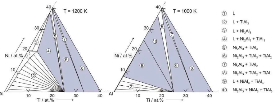
Initial assessment of the phases likely in the Ti-doped system was undertaken by CALPHAD modelling using the software package MTDATA [26]. Data for the Al-Ni-Ti ternary system was obtained from version 5.0 of the SGTE solutions database, with MTDATA being used to generate isothermal ternary phase-diagrams and to conduct Scheil-type simulations of the solidification pathway.
For the XRD measurements, two methods of sample mounting were employed. Firstly, all four of the alloys in both of the size fractions were measured by loading the powder onto a low-background silicon single crystal sample holder. Secondly, the two 1.5 at.% Ti samples were mounted in Buehler transoptic resin then ground and polished to a 1 µm surface finish prior to measurement. The second approach was employed as it is known that XRD measurements are weighted in favour of the surface of the particle due to attenuation of the X-rays as they pass through the material. Therefore, by mounting, grinding and polishing it is possible to obtain measurements characteristic of the entire cross section of the particles, thereby checking for any surface effects. However, the second method also has drawbacks in that the quantity of material measured is less, leading to poorer statistics, and the mount material produces a strong amorphous background count. Hence, the two techniques are complementary to each other.
In all cases XRD measurements were performed on a Philips XPert diffractometer using Cu-Kradiation. Crystallographic and quantitative phase fraction information was extracted from the resulting diffraction patterns by Rietveld refinement, using the General Structure Analysis Software (GSAS) package [27] and associated EXPGUI [28] graphical user interface.
For SEM and EDX analysis particles were mounted in Buehler transoptic resin, ground, polished to a 1 µm surface finish and coated with a thin conductive layer of carbon. The samples were then inspected using a Carl Zeiss EVO MA15 microscope, fitted with an Oxford Instruments EDX system.
3
Experimental Results
CALPHAD Modelling
Figure 1 – Al-rich corner of the Al-Ni-Ti ternary phase diagram at T = 1200 K and at T = 1000 K.
XRD measurements
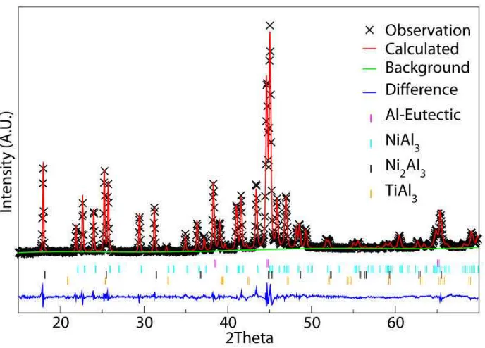
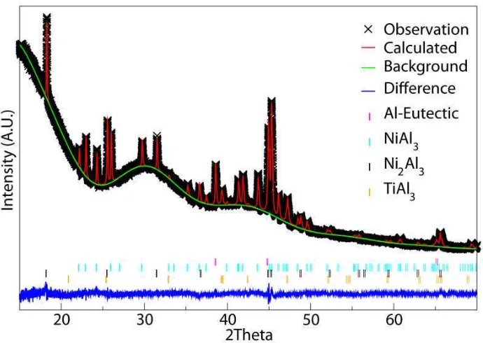
Analysis of the XRD patterns obtained from the undoped Al-25 at.%Ni alloy indicates that, as expected it is composed of three phases, Ni2Al3, NiAl3, and Al-Eutectic. Figure 2 shows the experimentally determined XRD pattern and the Rietveld fitting for the 53 - 38 µm sieve fraction. However, for the Ti-doped alloys, irrespective of the doping level, the XRD patterns are found to contain additional peaks. These can be completely accounted for by the inclusion within the Rietveld model of a single additional phase with the tetragonal TiAl3 structure (space group I4/mmm, International Symmetry Tables number 139), as predicted by the CALPHAD simulations. Figures 3 and 4 show examples of the experimental data and the Rietveld fit for the 53 - 38 µm sieve fraction of the 1.5 at.% Ti alloy, with Figure 4 being for the mounted, ground and polished sample, wherein the strong amorphous background from the mounting compound is also evident.
Figure 2– Diffraction pattern and Rietveld fit for the 53-38 µm sieve fraction of the undoped Al-25 at.%Ni alloy.
[image:7.595.126.470.410.657.2]Figure 4– Diffraction pattern and Rietveld fit for the mounted, ground and polished 38-53 sieve fraction of the 1.5 at.%Ti doped alloy.
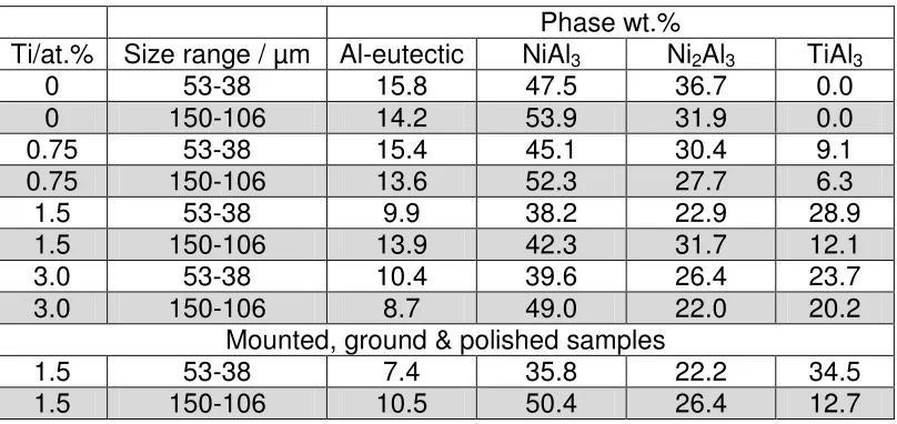
Table 1– Phase weight fractions for the various alloys and size fractions obtained from XRD measurements on both unmounted and mounted and polished powder samples
Phase wt.%
Ti/at.% Size range / µm Al-eutectic NiAl3 Ni2Al3 TiAl3
0 53-38 15.8 47.5 36.7 0.0
0 150-106 14.2 53.9 31.9 0.0
0.75 53-38 15.4 45.1 30.4 9.1
0.75 150-106 13.6 52.3 27.7 6.3
1.5 53-38 9.9 38.2 22.9 28.9
1.5 150-106 13.9 42.3 31.7 12.1
3.0 53-38 10.4 39.6 26.4 23.7
3.0 150-106 8.7 49.0 22.0 20.2
Mounted, ground & polished samples
1.5 53-38 7.4 35.8 22.2 34.5
[image:9.595.97.501.103.294.2]1.5 150-106 10.5 50.4 26.4 12.7
Table 2– Site occupancy calculation for unmounted and mounted and polished powder samples assuming Ni substitution on Ti sites in the TiAl3structure
Ti/at.% Size range / µm Calculated Ti-site occupancy in TiAl3
Ti / % Ni / %
0.75 53-38 32.5 67.5
0.75 150-106 46.3 53.7
1.5 53-38 20.5 79.5
1.5 150-106 48 52.0
3.0 53-38 49.1 50.9
3.0 150-106 57.2 42.8
Mounted, ground & polished samples
1.5 53-38 17.1 82.9
1.5 150-106 45.6 54.4
Microstructural Characterisation
Example SEM micrographs of the undoped and Ti-doped samples are given in Figure 5 a-b. In both cases the powders are taken from the 150-106 µm sieve fraction, with the doped sample having 1.5 at.% Ti. The images have been taken using the back-scatter detector, giving atomic number contrast. In Figure 5a fragmented dendritic cores of Ni2Al3are evident as light grey features, with each core being encased in a shell of NiAl3, which appear as mid-grey. This core-shell morphology is characteristic of the peritectic reaction via which the NiAl3phase is formed. The eutectic appears black in the figure, being almost entirely Al. The microstructure of the doped sample is relatively similar in appearance, also consisting of short dendritic fragments comprising Ni2Al3 cores enclosed within NiAl3 shells. The dendrites have a somewhat finer appearance, this almost certainly reflecting the lower volume fraction of Ni2Al3formation.
occurred. Careful inspection of Figure 5 reveals a needle like morphology in the doped sample not found in the undoped sample which correlates with the position of the Ti localisation. This morphology appears as dark grey, intermediate in shade between the NiAl3 and Al eutectic. Given that the only additional phase identified in XRD, and the localisation of Ti to this morphology, we are relatively confident that these needle like crystals are the I4/mmm TiAl3 phase. The EDX analysis reveals virtually no Ti elsewhere in the microstructure, suggesting very little substitution of Ti for Ni in either the Ni2Al3 or NiAl3 phases.
Figure 5– SEM backscatter image of (a) undoped Raney-type precursor alloy (Al-25 at.%Ni) and (b) equivalent 75 at.% Al alloy doped with 1.5 at.% Ti.
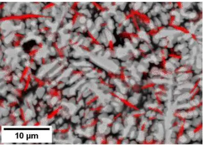
Figure 6 – SEM backscatter image of a Ti-doped Raney-type precursor alloy as shown in Figure 5b but with the Ti EDX map overlaid. Strong localisation of the Ti is evident which can be correlated with needle like crystals of TiAl3in Figure 5b.
4
Discussion and Analysis
[image:10.595.201.400.407.552.2]solidification phase in the binary system is NiAl, with Ni2Al3being formed via the peritectic reaction NiAl + L Ni2Al3. In contrast, below 26 at.% Ni ( 41 wt.% Ni) Ni2Al3 is the primary solidification phase (note that in Figure 1 both isothermal sections are plotted below the NiAl + L Ni2Al3 peritectic temperature of 1410 K, hence the absence of NiAl in these sections).
NiAl is a B2 cubic phase with a wide compositional stability field extending from 42 – 69 at.% Ni. On the Al-rich side, the deviation from stoichiometry is accommodated by the inclusion of vacancies on the Ni lattice sites [20], with the number of unoccupied Ni-sites approaching one third as the Ni2Al3 stoichiometry is approached. Upon the peritectic transformation of NiAl to Ni2Al3 the structure changes, with the Ni2Al3 structure being essentially a trigonal extension of the cubic B2 (NiAl) structure, with every third plane of Ni atoms perpendicular to the trigonal axis missing [29]. Conversely, moving to the Al-rich side of the Ni2Al3stoichiometry does not lead to additional vacancies being introduced, but rather leads to Al replacing Ni on the existing occupied Ni sites [29].
It seems likely therefore that the differences observed in the distribution of Ti in the as-solidified samples relate to the origin of the Ni2Al3 phase. Where this is formed via the peritectic decomposition of NiAl it appears that significant Ti concentrations can be incorporated into the Ni2Al3 phase, with Gros et al. [20] finding direct evidence the retention of small NiAl cores in Ti-rich Ni2Al3 dendrites. Conversely, where the Ni2Al3 phase has grown direct from the melt it appears that Ti is almost completely excluded from the Ni2Al3 phase, instead forming a (TixNi1-x)Al3phase with the DO22crystal structure. The origin of the Ni2Al3 phase, whether by the peritectic conversion of NiAl or by direct solidification from the melt, has also recently been shown to have an effect on undoped Al-rich Ni-Al alloys [30], with that produced by the peritectic being less amenable to subsequent NaOH leaching than that solidified direct from the melt.
As the cooling rate is increased the phase fraction of TiAl3 increases (at fixed Ti concentration), suggesting that the Ni occupancy of the Ti-sites increases with increasing cooling rate. However, despite the localisation of the Ti to a phase not normally associated with being a catalytically active constituent of Raney-type Ni catalysts, catalytic testing on powders of this material [23] show more than twice the activity of the equivalent undoped catalyst for the hydrogenation of butyraldehyde (based on the 150-106 m diameter sieve fraction for both the doped and undoped powders and the 1.5 at.% Ti alloy). This suggests that the DO22 (TixNi1-x)Al3 phase identified in this study can be leached relatively easily by NaOH in much the same way as NiAl3 and subsequently forms a catalyst with a very high activity.
References
[1] S.R. Montgomery, Catalysis of Organic Reactions, Marcel Dekker, New York, 1981. [2] Catalytic hydrogenation of carboxylic acids and esters, in, Kyowa Hakko Kogyo Co. Ltd., GB, 1966.
[3] R.J. Allain, V.L. Seale, Acrylonitrile hydrolysis and catalyst useful therefor, in, Nalco Chemical Co., US, 1975.
[4] M. Raney, Method of producing finely-divided nickel, in, US, 1927.
Ni-Al alloy samples on the catalytic performance of Raney-type nickel catalysts, Appl. Catal. A, 356 (2009) 154-161.
[6] P. Fouilloux, G.A. Martin, A.J. Renouprez, B. Moraweck, B. Imelik, M. Prettre, Texture and structure of Raney nickel, J. Catal., 25 (1972) 212-222.
[7] R. Wang, H. Chen, Z. Lu, S. Qiu, T. Ko, Structural transitions during aluminum leaching of NiAl3 phase in a Raney Ni-Al alloy, J. Mater. Sci., 43 (2008) 5712-5719.
[8] M.L. Bakker, D.J. Young, M.S. Wainwright, Selective leaching of nickel-aluminum (NiAl3and Ni2Al3) intermetallics to form Raney nickels, J. Mater. Sci., 23 (1988) 3921-3926. [9] H. Warlimont, U. Kuehn, N. Mattern, Rapidly quenched Raney catalyst precursors, Mater. Sci. Eng. A, 226-228 (1997) 900-904.
[10] H. Lei, Z. Song, D. Tan, X. Bao, X. Mu, B. Zong, E. Min, Preparation of novel Raney-Ni catalysts and characterization by XRD, SEM and XPS, Appl. Catal. A, 214 (2001) 69-76. [11] C.M. Bao, U. Dahlborg, N. Adkins, M. Calvo-Dahlborg, Structural characterisation of Al-Ni powders produced by gas atomisation, J. Alloys Compd., 481 (2009) 199-206.
[12] A. Ilbagi, H. Henein, A.B. Phillion, Phase quantification of impulse atomized Al68.5Ni31.5 alloy, J. Mater. Sci., 46 (2011) 6235-6242.
[13] F. Devred, G. Reinhart, G.N. Iles, B. van der Klugt, N.J. Adkins, J.W. Bakker, B.E. Nieuwenhuys, Synchrotron X-ray microtomography of Raney-type nickel catalysts prepared by gas atomisation: Effect of microstructure on catalytic performance, Catal. Today, 163 (2011) 13-19.
[14] D. Tourret, G. Reinhart, C.-A. Gandin, G.N. Iles, U. Dahlborg, M. Calvo-Dahlborg, C.M. Bao, Gas atomization of Al-Ni powders: Solidification modeling and neutron diffraction analysis, Acta Mater., 59 (2011) 6658-6669.
[15] A.M. Mullis, L. Farrell, R.F. Cochrane, N.J. Adkins, Estimation of cooling rates during close-coupled gas atomization using secondary dendrite arm spacing measurement, Metall. Mater. Trans. B, 44 (2013) 992-999.
[16] Y. Kiros, M. Majari, T.A. Nissinen, Effect and characterisation of dopants to Raney nickel for hydrogen oxidation, J. Alloys Compd., 360 (2003) 279-285.
[17] K. Mund, G. Richter, F. von Sturm, Titanium-containing Raney nickel catalysts for hydrogen electrodes in alkaline fuel cell systems, Journal of Electrochemical Society, 124 (1977) 1-6.
[18] P. Salvi, P. Nelli, M. Villa, Y. Kiros, G. Zangari, G. Bruni, A. Marini, C. Milanese, Hydrogen evolution reaction in PTFE bonded Raney-Ni electrodes, Int. J. Hydrogen Energy, 36 (2011) 7816-7821.
[19] U. Dahlborg, C.M. Bao, M. Calvo-Dahlborg, F. Devred, B.E. Nieuwenhuys, Structure and microstructure of leached Raney-type Al-Ni powders, J. Mater. Sci., 44 (2009) 4653-4660.
[20] J. Gros, S. Hamar-Thibault, J.C. Joud, Influence of additions on the structure of rapidly solidified Ni2Al3 alloys, J. Mater. Sci., 24 (1989) 2987-2998.
[21] J. Pardillos-Guindet, S. Metais, S. Vidal, J. Court, P. Fouilloux, Electrode potential of a dispersed Raney nickel elctrode during acetone hydrogenation: Influence of the promoters, Appl. Catal. A, 132 (1995) 61-75.
[22] T. Kenjo, Doping effects of transition metals on the polarization characteristics in Raney nickel hydrogen elctrodes, Electrochemical Acta, 33 (1988) 41-46.
[23] F. Devred, B.E. Nieuwenhuys, IMPRESS Deliverable Report D2b-9, in, Leiden University, The Netherlands, 2009.
[24] V. Anand, A.J. Kaufman, N.J. Grant, Rapid solidification processing: Principles and technologies II, Claitor, Baton Rouge, LA, 1978.
[26] U. Licensed by the National Physical Laboratory, MTDATA, in.
[27] A.C. Larson, R.B. Von Dreele, General Structure Analysis System (GSAS), in, Los Alamos National Laboratory, 2004.
[28] B.H. Toby, EXPGUI, a graphical user interface for GSAS, J. Appl. Crystallogr., 34 (2001) 210-213.
[29] A. Taylor, N.J. Doyle, Further studies on the nickel-aluminium system. I. The beta-NiAI and delta-Ni2AI3 phase fields, J. Appl. Crystallogr., 5 (1972).