This is a repository copy of The role of micro-cavitation on EHL: A study using a multiscale mass conserving approach.
White Rose Research Online URL for this paper: http://eprints.whiterose.ac.uk/127582/
Version: Accepted Version
Article:
Gao, L, de Boer, G orcid.org/0000-0002-5647-1771 and Hewson, R (2015) The role of micro-cavitation on EHL: A study using a multiscale mass conserving approach. Tribology International, 90. pp. 324-331. ISSN 0301-679X
https://doi.org/10.1016/j.triboint.2015.04.005
© 2015, Elsevier Ltd. Licensed under the Creative Commons Attribution NonCommercial-NoDerivatives 4.0 International
http://creativecommons.org/licenses/by-nc-nd/4.0/
[email protected] https://eprints.whiterose.ac.uk/ Reuse
This article is distributed under the terms of the Creative Commons Attribution-NonCommercial-NoDerivs (CC BY-NC-ND) licence. This licence only allows you to download this work and share it with others as long as you credit the authors, but you can’t change the article in any way or use it commercially. More
information and the full terms of the licence here: https://creativecommons.org/licenses/
Takedown
If you consider content in White Rose Research Online to be in breach of UK law, please notify us by
1
The role of micro cavitation on EHL: a study using a
1
multiscale mass conserving approach
2 3
Leiming Gao
1), Gregory de Boer
2)and Rob Hewson
3)4 5
1),3)
Department of Aeronautics, Imperial College London, London, SW7 2AZ, UK
6
2)
School of Mechanical Engineering, University of Leeds, Leeds, LS2 9JT, UK
7 8
1)
Corresponding author, Email: [email protected]; Tel: +44 (0)20 7594 1976
9 10 11 12
KEYWORDS
13 14
Cavitation; Multiscale; Textured Surface; Elastohydrodynamic Lubrication (EHL).
15
16 17
ABSTRACT
18 19
The role of micro cavitation in Elastohydrodynamic Lubrication is numerically investigated
20
using a multiscale approach whereby both the small scale topographical features and the
21
micro-cavitation of the lubricant due to the features are resolved. Micro-cavitation and the
22
fluid shear-thinning property are modelled at the small scale of topological feature. The
23
effects of topographical features on the film thickness of the line contact bearings and friction
24
coefficient are presented with a focus on the role of micro-cavitation. This highlights how a
25
mass conserving small scale model can be used to model both micro-cavitation and cavitation
26
occurring at the bearing scale, and how topological features can be designed to reduce friction
27
while maintaining bearing load.
28
2
1 INTRODUCTION
1 2
In this paper the role of cavitation in an Elastodhydrodynamic Lubrication (EHL)
converging-3
diverging line contact is investigated. The bearing surfaces are a smooth moving roller surface
4
relative to a stationary, textured flat surface. Topographical changes to a lubricated surface of
5
industrial components have been experimentally and numerically shown to improve their
6
tribological performance in three main aspects, the load carrying capacity, the friction
7
coefficient and the lubricant fluid film [1, 2]. Such applications include piston rings [3, 4],
8
mechanical seals [5, 6], journal bearings [7, 8], pad bearings [9-12] and roller bearings in line
9
contacts [13-17] and point contacts [18, 19].
10
A number of numerical approaches have been proposed to represent lubrication of surfaces
11
with topographical features [7, 17, 18, 20, 21]. One of the challenges of numerically describing
12
these problems is the order of magnitudes difference in the size of bearing surface topography
13
and the bearing itself. This has led to a number of multiscale methodologies to analyse the
14
problem and overcome the limitation in terms of computing costs [22-26]. Among the
15
multiscale models, many of them employ an adapted Reynolds equation based on Patir and
16
C average flow model [27] to solve the large scale fluid pressure, and the Stokes or
17
Navier-Stokes equations to solve the small scale fluid flow [22, 24, 26]. Recently, the
18
homogeneous multiscale approach has been developed, in which the large scale fluid flow was
19
governed by a homogeneous pressure-gradient function whose coefficient was obtained from
20
the small scale simulations. These include the work of Nyemeck et al. [25] on the
21
hydrodynamic lubrication with rigid bearing surfaces of seals [11, 12] on
22
the EHL simulation of micro-textured pad bearings.
23
The role of micro-cavitation on lubrication has been studied by a number of investigators
24
arising from experimental observation of cavitation occurring in the vicinity of surface
25
roughness [20, 28]. The role of cavitation raises further questions regarding the validity of
26
using a form of the lubrication equation, where cavitation effects may not be uniform across
27
the film thickness due to the underlying topography; this cannot be captured by the lubrication
28
approximation where a constant pressure is assumed across the film thickness. Olver et al. [29]
29
proposed cavitation pressures located in the
3
inlet region of the pad bearing surface. Ausas et al. [30] and Qiu and Khonsari et al. [31]
1
studied micro-cavitation in textured bearing lubrication using a mass conserving model and
2
compared different boundary conditions of cavitation; the half-Sommerfield condition,
Swift-3
Steiber (Reynolds) condition and the Floberg Jakobsson Olsson (JFO) condition. It was found
4
that the Reynolds condition largely underestimated the cavitation area and predicted a higher
5
load-carrying capacity than the JFO results. Other studies of micro-cavitation have used
Navier-6
Stokes based Computational Fluid Dynamics (CFD) simulations to solve the fluid flow, for
7
example, Shi and Ni [32], Wahl et al. [33] and Meng and Yang [34]. However, these studies of
8
micro-cavitation were all modelled at a single scale, where the topographical features were
9
described over the entire lubrication domain. The number of simulated micro dimples or
10
grooves in these studies was limited to up to 10 due to the very fine mesh required to resolve
11
the small scale features and cavitation. In real engineering applications the number of micro
12
dimples (and roughness) could be much larger on a real textured surface, and a
13
multiscale method is especially relevant to solve such problem.
14
In this paper the heterogenous multiscale method (HMM) [35] is applied to EHL as derived
15
by the authors [11, 12, 36] and extended to include cavitation effects, via the application of a
16
mass-conserving approach at both small and large scales. This enables the model to capture
17
cavitation at both scales. The pressure gradient-mass flow rate relationship is obtained from a
18
homogenised local scale solution. This relationship is subsequently used at the global scale as a
19
governing equation of fluid flow, and solved along with the conservation of mass. In this work
20
cavitation is considered at the local scale via a predefined threshold cavitation pressure. The
21
effects of the
micro-22
thickness and friction coefficient are presented. The piezo-viscous and shear-thinning effects
23
are discussed and the importance of the role of micro cavitation at the small scale is
24
highlighted.
25
26
2 NUMERICAL METHODOLOGY
27 28
2.1 Geometry and Materials
4
In this study, the global geometry of the lubrication model is a two-dimensional cylindrical
1
line contact. The smooth cylinder rotates relative to a textured stationary surface, as shown in
2
Fig. 1. The material of the plane is PTFE with an elastic modulus (E) GP P
3
ratio ( ) of 0.4. The cylinder is assumed to be rigid compared to the soft PTFE bearing surface.
4
The radius of the cylinder (r) is 25 mm and the rotation speed ( ) is 80 rad/s, and equivalent to
5
a sliding speed (U0) of 2 m/s. The micro-pocket length (L) ranges from 20 m and 100 m and 6
the depth (d) from 0 m and 30 m. The geometrical and material parameters are listed in
7
Table 1.
8
9
2.2 Large Scale Simulation
10
The large scale simulation describes the fluid-structure interaction in the global lubrication
11
domain, where the fluid pressure is solved simultaneously with the elastic deformation of the
12
bearing surfaces. The difference between the current study and classical EHL analysis is that
13
the governing equation for the hydrodynamic pressure is a homogenised equation from the
14
small scale simulations, rather than the Reynolds equation, expressed as
15
(1)
together with the mass conservation equation
16
(2)
The pressure gradient ( ) is a homogenised function of the pressure ( ), mass flow rate ( )
17
and film gap (g), interpolated from a series of small scale solutions. The large scale boundary
18
conditions used to solve Eqs. (1) and (2) are that the pressure at the bearing inlet and outlet
19
boundaries is equal to zero:
20
(3)
The line contact bearing load is balanced by an integral of the average small scale pressure
21
(i.e., load per unit length ), along the line contact domain. The average small scale pressure
22
( ) was defined in Eq. (17) in the Section 2.3.1 Small Scale Simulations
23
5
The geometry equation is expressed as a sum of the rigid displacement (e, an unknown
1
constant determined by load w), rigid gap geometry and the surface deformation ( ):
2
(5)
(6)
where the displacement influence coefficient matrix K G
3
[37] for linear elastic contact model.
4
5
2.3 Small Scale Simulations
6
The small scale problem is described by the flow equations and those governing the elastic
7
deformation of the small scale features. The coupling is facilitated through the application of
8
the Arbitrary Largrangian Eularian (ALE) method to describe the fluid domain as the solid
9
domain deforms and the inclusion of non-Newtonian, piezo-viscous and cavitation effects are
10
included.
11
12
2.3.1Solid Structure Model
13
The small scale solid domain is described by a plain strain model with the separation of the
14
displacement influence coefficient matrix K into local (diagonal, K1) and global (off-diagonal,
15
K2) terms [12]. The film gap (g) at the small scale is described by the sum of undeformed gap
16
and the non-local deformation ( ), not including the local deformation .
17
(7)
The local terms are represented as part of the local fluid-structure interaction simulation, and
18
the global terms are applied as they would be in a conventional EHL simulation. An equivalent
19
height of the solid domain is introduced in order to ensure that the local deformation in the
20
small scale simulations is the same as the column deformation obtained from the diagonal
21
matrix. For further details of the structure model the reader is referred to references [12].
22
23
2.3.2Laminar Flow Model
6
The steady-state, isothermal and laminar flow is governed by the compressible
Navier-1
Stokes equations:
2
(8)
(9)
where, u is the fluid velocity vector and I the unit tensor. is the generalized fluid density
3
which is a function of pressure based on Dowson-Higginson formula [38],
4
(10)
where, and are the density-pressure coefficients, is the density at ambient pressure,
5
is the density fraction of liquid in the liquid and gas mixture and is defined in the cavitation
6
model in Section 2.3.2. Piezo-viscous effects are described by an exponential relationship [39],
7
the viscosity of liquid and gas mixture is expressed as:
8
exp (11)
with the pressure-viscosity coefficient . Considering the fluid shear-thinning property, the
9
generalized viscosity * is defined using a Carreau viscosity model [40] below.
10
(12)
where, is shear rate. and represent the dynamic viscosity at zero shear rate and
11
infinite shear rate, respectively. is critical stress at ambient pressure. The piezo-viscous
12
effect described in Eq. (11) and the shear-thinning property defined in Eq. (12) are illustrated in
13
Fig. 2.
14
The boundary conditions are shown in Fig. 1b. The lower boundary CD (Fig. 1b) is a sliding
15
wall. The upper fluid-structure interface is a no slip boundary. In heterogenous multiscale
16
method, periodic boundary conditions are required on the AD and BC boundary in terms of
17
fluid velocity and pressure. Due to small scale deformation the two boundary geometries are
18
not exactly the same, therefore, the boundary BC was scaled to the same length of boundary
19
AD in the reference coordinates (undeformed gap) [12]. Near-periodic velocity boundary
20
conditions are derived from the mass conservation at the two boundaries, scaled by the local
21
strain :
22
7
and a pressure jump (p) is applied onto the scaled boundaries:
1
(14)
where, subscript 1 and 2 represent the scaled boundary AD and BC in Fig. 1b respectively. Since
2
the moving wall (lower surface) was fully constrained, i.e. there was no deformation allowed
3
and the strain was zero, the velocities at both sides of the fluid domain on the moving wall
4
surface were the same. Thus the nearly periodic conditions described in Eq. (Error! Reference
5
source not found.) are the same as periodic conditions at the moving surface and it satisfies
6
the no-slip boundary conditions.
7
The homogenised pressure gradient ( ) across a unit cell and a pressure jump across the small
8
scale cell is described by:
9
(15)
The mass flow rate ( ) is calculated as:
10
(16)
An average pressure (p*) is defined to represent the cell pressure in large scale solutions:
11
(17)
The shear stress (shear force per unit length) is calculated as:
12
(18)
13
2.3.3Cavitation Model
14
The lubricant is assumed to be a homogeneous mixture of liquid and gas. When the fluid
15
pressure drops below the saturation pressure cavitation occurs and some gas dissolved in fluid
16
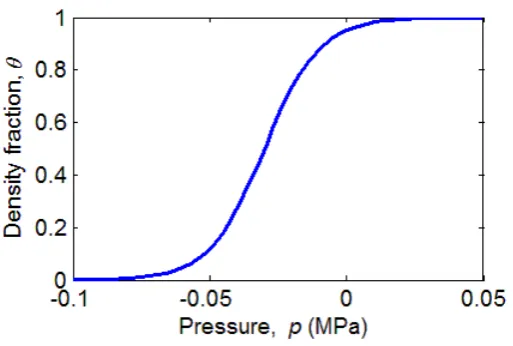
will come out of solution. The density fraction of liquid ( ) is defined as a continuous function
17
of pressure using the hyperbolic tangent function:
18
8
The constants are used to determine the steep gradient of the density fraction with respect
1
to a threshold cavitation pressure KPa. The variation of against pressure is shown
2
in Fig. 3. The relationship described here is similar to the polynomial based approach used by
3
Almqvist and Larsson [41], to describe the density of lubricant with the fluid pressure. The
4
parameters of fluid properties are given in Table 2, and are based on mineral oil of the type
5
typically used as bearing lubricant [42, 43].
6
7
8
2.4 Homogenisation of the pressure gradient equation
9
The homogenised relationship between the pressure gradient and mass flow rate links the
10
small scale and large scale simulations. This relationship is obtained via interpolation. In order
11
to obtain an accurate representation of the small scale model, a range of small scale
12
simulations were undertaken for a range of gaps (g), homogenised pressure gradients and
13
cell inlet pressures (p1). A linear interpolation function was adopted, based on a Delaunay 14
triangulation of the data using Quickhull algorithm as implemented in Matlab [44]. To obtain
15
effective data samples for the interpolation, the range of input parameters are selected as
16
shown in Table 3 with total number of 3000 sample points, based on the corresponding results
17
of the smooth surface case of Reynolds equation.
18
19
Small scale solutions were obtained using the finite element method as implemented in
20
COMSOL Multiphysics. The variables are transformed to the non-dimensional forms for
21
convenience of numerical computing, for the global scale,
22
(20)
and for the small scale,
23
(21)
24
where is the Hertzian contact radius,
9
(22)
Subsequently, the pressure gradient equation is obtained via linear interpolation,
1
(23)
where the first four parameters on the right-hand side ( ) were known and obtained
2
from small scale analysis. n denotes the mesh points at the large scale domain. The
non-3
dimensional mass conservation equation is expressed as,
4
(24)
5
6
3 Results
7
A non-dimensional large scale domain of X = [ 4, 2] and a fixed load of 2500 N was
8
considered in this study. Large scale mesh independence tests were undertaken from 60 to 960
9
points in the large scale domain. For the Newtonian case with a smooth surface, the relative
10
errors in the large-scale pressure and mass flow rate using different mesh are presented in
11
Fig.4 (a), and the large-scale pressure distributions are compared in Fig.4 (b) and (c). The
12
presence of smooth surface solutions allowed comparison with the solution obtained using
13
Reynolds equation. In current study the number of mesh nodes n was set at 120, at which level
14
the relative errors were approximately 7% and 5% in pressure and mass flow rate respectively.
15
Four fluid viscosity models were investigated, i.e. (i) Newtonian, (ii) Newtonian and
piezo-16
viscous, (iii) shear-thinning, and (iv) both piezo-viscous and shear-thinning. In each model, a
17
range of cell lengths (L = 20, 50 and 100 m) and depths (d = 0 30 m, increased by 5 m)
18
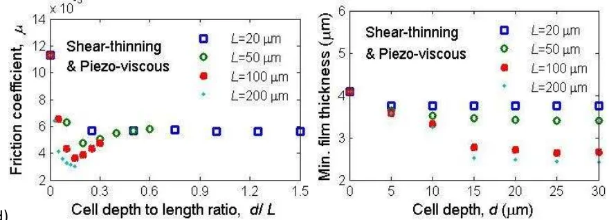
were considered. The friction coefficient and minimum film thickness are presented in Fig. 5.
19
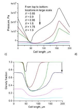
Typical results showing how cavitation is captured at the large scale is shown in Fig. 6 (a) and
20
(b) for the case of L = 100 m and d = 30 m, where the large scale homogenised pressure and
21
viscosity are presented from the small scale simulations, and the elastic deformation of the
22
bearing surface also presented. The development of cavitation at small scale is demonstrated
10
in Fig. 6 (c) and (d), in the large scale outlet zone in the region of X = [0.8, 1.8]. The role of
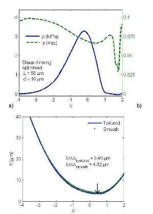
1
shear thinning fluid properties is demonstrated in Fig. 7, where the homogenised viscosity is
2
clearly observed to decrease in the main loading domain at the large scale. The combination of
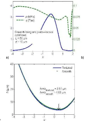
3
both piezo-viscosity and shear-thinning effect on the pressure, viscosity and film thickness is
4
shown in Fig. 8.
5
6
4 Discussion
7
8
4.1. Fluid Rheology
9
It can clearly been seen from these results that through the careful selection of small scale
10
depth and length, that the friction coefficient can be reduced. The friction coefficient is
11
presented as a function of the depth to length ratio (d/L) in Fig. 5, these results imply that
12
there is an optimal cell depth and length to achieve minimum friction. For example, in the
13
Newtonian cases, for the cell length L = 50 µm the minimum friction coefficient was observed
14
with the cell depth d = 10 µm and the reduction in the friction coefficient is 42% compared to
15
the smooth surface; for the cell length L= 100 µm the friction coefficient is reduced by 52%
16
when the cell depth d is 15 µm. This is similar to the results previously obtained by Gao and
17
Hewson [36] who obtained a similar trend for a slider bearing with the same small scale
18
surface features. In these cases there was a monotonic decrease in the friction with increasing
19
small scale length to depth ratio (d/L). What is interesting to note is that contrary to the
20
previous case there is a clear minimum friction coefficient predicted for a cell depth to length
21
ratio of around 0.15 for the cases of µm. In the previous case it was observed that the
22
friction coefficient decreased then plateaued out to a near constant friction coefficient with
23
increasing cell depth.
24
While the different fluid rheologies considered all exhibit similar characteristics it should be
25
noted that the reduction in friction is most pronounced for the shear thinning fluid
26
characteristics, where there is a 3 fold decrease in the friction coefficient for the largest cell
27
geometry L = 100 µm. The effect of piezo-viscous is not significant for a low pressure values
28
encountered in the current study. The variations in the pressure, viscosity and film thickness
11
are less than 10% by comparing the results with or without piezo-viscous effect considered, as
1
shown in Figs. 7 and 8.
2
The minimum film thickness decreases with increasing cell depth as shown in Fig. 5, and this
3
has been reported in other EHL studies of textured surface [18, 20, 45]. Examining the
4
minimum film thickness shows how there is a clear compromise to be made between reducing
5
friction and maintaining a reasonable fluid film, as the effect of topography is to reduce the
6
minimum film thickness, with the greatest effect observed for the shear thinning fluid model.
7
The reasonable fluid film should have a minimum value which is double or triple the surface
8
roughness, i.e. the lambda ratio is 2 or 3, which means the bearing could operate in the mixed
9
or full film lubrication regime. 10
11
4.2. Micro-Cavitation
12
Cavitation was included in the small scale geometry, permitting the modelling of the
13
converging-diverging geometry to be modelled without a specific large scale treatment of
14
cavitation. The pressure distributed over the whole lubrication domain was governed by the
15
homogenised pressure equation. This is different from classical EHL models, where the
16
Reynolds boundary condition (pressure is positive everywhere) is commonly applied in the
17
diverging geometry. Since the small scale pocket itself is a divergent-convergent geometry, the
18
local pressure usually decreases at the inlet divergent edge, and then increase at the outlet
19
convergent edge. When there is limited cavitation in the small scale the local pressure
20
distributed is nearly anti-symmetrically (as shown by the top curve in Fig. 6 (c), at location X =
21
0.8). When cavitation extended towards outlet zone, i.e. X increases, the pressure field
22
diverges from this. The cavitation region can be observed in Fig. 6 (d) where the region of low
23
density fraction indicates a larger cavitated zone as X increases. As the region of cavitation
24
increases further the local pressure became nearly constant of 30 KPa (as shown by the
25
bottom curve in Fig. 6 (c), at location X = 1.8).
26
What is interesting is that there is a rise in viscosity in the diverging region before cavitation
27
occurs as shown in Fig. 7. This can also be observed when piezo-viscosity is also added to the
28
model as is shown in Fig. 8.
12 1
5 CONCLUSION
2
A heterogeneous multiscale model has been developed for the fluid-structure interaction in
3
cylindrical line contact EHL with the bearing surface topography addressed. Fluid cavitation is
4
explicitly modelled at the small scale via a continuous function of the fluid density and viscosity
5
with pressure. The small scale cavitation effects are passed to the large scale model via the
6
homogenised small scale relationship without further large scale treatment of cavitation. Such
7
an approach also allows a range of rheological models to also be considered. The
shear-8
thinning effects have been found to have significant effect on the bearing performance as well
9
as the optimum small scale features required for optimum performance.
10
11
ACKNOWLEDGEMENT
12
The authors would like to thank the Engineering and Physical Sciences Research Council
13
(Grant number EP/I103733/1) and the Leverhulme Trust (Grant number F/10 100/B) for the
14
financial support to this work.
15
16
NOMENCLATURE
17 18
d Cell depth [m]
E Y [Pa]
E Y [Pa]
e Rigid displacement [m] h Large scale film thickness [m] g locally undeformed gap [m]
K Displacement influence coefficient matrix [m N] L Cell length [m]
n Number of large-scale mesh grid p Pressure [Pa]
pc Threshold cavitation pressure [Pa]
Mass flow rate per unit length [kg/m/s] r Radius of cylinder [m]
Equivalent small-scale cell height [m]
13
u Fluid velocity vector [m/s]
w One-dimensional load per unit length [N/m] x Coordinate in direction of fluid flow [m] X Dimensionless coordinate of x
Pressure-viscosity coefficient Shear rate [1/s]
Elastic deformation [m] Strain
Viscosity at zero shear rate [Pa s] Viscosity at infinite shear rate [Pa s]
Generalized viscosity in Carreau model [Pa s] Density fraction in cavitation model
Friction coefficient Normal stress [Pa] Shear stress [Pa] P
Ambient fluid density [kg m ] Generalized fluid density [kg m ] Rotation velocity of cylinder [rad/s]
1 2 3 4 REFERENCES 5 6
[1] Segu DZ, Choi SG, Choi JH, Kim SS. The Effect of Multi-Scale Laser Textured Surface on 7
Lubrication Regime. Appl Surf Sci. 2013;270:58-63. 8
[2] Braun D, Greiner C, Schneider J, Gumbsch P. Efficiency of laser surface texturing in the 9
reduction of friction under mixed lubrication. Tribol Int. 2014;77:142-47. 10
[3] Ryk G, Etsion I. Testing piston rings with partial laser surface texturing for friction 11
reduction. Wear. 2006;261:792-96. 12
[4] Tomanik E. Modelling the hydrodynamic support of cylinder bore and piston rings with laser 13
textured surfaces. Tribol Int. 2013;59:90-96. 14
[5] Etsion I, Kligerman Y, Halperin G. Analytical and Experimental Investigation of Laser-15
Textured Mechanical Seal Faces. Tribol Trans. 1999;42:511-16. 16
[6] Brunetiere N, Tournerie B. Numerical analysis of a surface-textured mechanical seal 17
operating in mixed lubrication regime. Tribol Int. 2012;49:80-89. 18
[7] Dobrica MB, Fillon M, Maspeyrot P. Mixed elastohydrodynamic lubrication in a partial 19
journal bearing-comparison between deterministic and Stochastic models. ASME J Tribol. 20
2006;128:778-88. 21
[8] Rao TVVLN, Rani AMA, Nagarajan T, Hashim FM. Analysis of slider and journal bearing 22
14
[9] Dobrica MB, Fillon M, Pascovici MD, Cicone T. Optimizing surface texture for 1
hydrodynamic lubricated contacts using a mass-conserving numerical approach. Proc Inst Mech 2
Eng, Part J: J Eng Tribol. 2010;224:737-50. 3
[10] Sharma SC, Yadav SK. Performance analysis of a fully textured hybrid circular thrust pad 4
bearing system operating with non-Newtonian lubricant. Tribol Int. 2014;77:50-64. 5
[11] de Boer GN, Hewson RW, Thompson HM, Gao L, Toropov VV. Two-scale EHL: 3D 6
Topography in Slider Bearings. Tribol Int. 2014;79:111-25. 7
[12] Gao LM, Hewson R. A Multiscale Framework for EHL and Micro-EHL. Tribol Trans. 8
2012;55:713-22. 9
[13] Hao LC, Meng YG, Chen C. Experimental investigation on effects of surface texturing on 10
lubrication of initial line contacts. Lubr Sci. 2014;26:363-73. 11
[14] Janakiraman S, Klit P, Jensen NS, Gronbaek J. Observations on the effects of grooved 12
surfaces on the interfacial torque in highly loaded rolling and sliding tests. Tribol Int. 13
2015;81:179-89. 14
[15] Marian VG, Predescu A, Pascovici MD. Theoretical analysis of an infinitely wide rigid 15
cylinder rotating over a grooved surface in hydrodynamic conditions. Proc Inst Mech Eng, Part 16
J: J Eng Tribol. 2010;224:757-63. 17
[16] Vrbka M, Krupka I, Samanek O, Svoboda P, Vaverka M, Hartl M. Effect of surface 18
texturing on lubrication film formation and rolling contact fatigue within mixed lubricated non-19
conformal contacts. Meccanica. 2011;46:491-98. 20
[17] Wang XL, Liu W, Zhou F, Zhu D. Preliminary Investigation of the Effect of Dimple Size 21
on Friction in Line Contacts. Tribol Int. 2009;42:1118-23. 22
[18] Zhu D, Nanbu T, Ren N, Yasuda Y, Wang QJ. Model-Based Virtual Surface Texturing for 23
Concentrated Conformal-Contact Lubrication. Proc Inst Mech Eng, Part J: J Eng Tribol. 24
2010;224:685-96. 25
[19] Kaneta M, Guo F, Wang J, Krupka I, Hartl M. Formation of Micro-Grooves Under Impact 26
Loading in Elliptical Contacts with Surface Ridges. Tribol Int. 2013;65:336-45. 27
[20] Mourier L, Mazuyer D, Ninove FP, Lubrecht AA. Lubrication Mechanisms with Laser-28
Surface-Textured Surfaces in Elastohydrodynamic Regime. Proc Inst Mech Eng, Part J: J Eng 29
Tribol. 2010;224:697-711. 30
[21] Minet C, Brunetiere N, Tournerie B. A Deterministic Mixed Lubrication Model for 31
Mechanical Seals. ASME J Tribol. 2011;133. 32
[22] de Kraker A, Ostayen R, Beek A, Rixen D. A Multiscale Method Modelling Surface 33
Texture Effects. ASME J Tribol. 2007;129:221-30. 34
[23] Demirci I, Mezghani S, Yousfi M, El Mansori M. Multiscale Analysis of the Roughness 35
Effect on Lubricated Rough Contact. ASME J Tribol. 2014;136. 36
[24] Jai M, Bou-Said B. A Comparison of Homogenization and Averaging Techniques for the 37
Treatment of Roughness in Slip-Flow-Modified Reynolds Equation. ASME J Tribol. 38
2002;124:327-35. 39
[25] Nyemeck AP, Brunetiere N, Tournerie B. A Multiscale Approach to the Mixed Lubrication 40
Regime: Application to Mechanical Seals. Tribol Lett. 2012;47:417-29. 41
[26] Sahlin F, Larsson R, Almqvist A, Lugt P, Marklund P. A Mixed Lubrication Model 42
Incorporating Measured Surface Topography. Part 1: Theory of Flow Factors. Proc Inst Mech 43
Eng, Part J: J Eng Tribol. 2010;224:335-51. 44
[27] Patir N, Cheng HS. Average Flow Model for Determining Effects of 3-Dimensional 45
15
[28] Shen C, Khonsari MM. On the Magnitude of Cavitation Pressure of Steady-State 1
Lubrication. Tribol Lett. 2013;51:153-60. 2
[29] Olver AV, T Fowell M, Spikes HA, Pegg IG. 'Inlet Suction', A Load Support Mechanism in 3
Non-Convergent, Pocketed, Hydrodynamic Bearings. Proc Inst Mech Eng, Part J: J Eng Tribol. 4
2006;220:105-08. 5
[30] Ausas R, Ragot P, Leiva J, Jai M, Bayada G, Buscaglia GC. The Impact of the Cavitation 6
Model in The Analysis of Microtextured Lubricated Journal Bearings. ASME J Tribol. 7
2007;129:868-75. 8
[31] Qiu Y, Khonsari MM. On the Prediction of Cavitation in Dimples Using a Mass-9
Conservative Algorithm. ASME J Tribol. 2009;131:041702. 10
[32] Shi X, Ni T. Effects of Groove Textures on Fully Lubricated Sliding with Cavitation. 11
Tribol Int. 2011;44:2022-28. 12
[33] Wahl R, Schneider J, Gumbsch P. In Situ Observation of Cavitation in Crossed 13
Microchannels. Tribol Int. 2012;55:81-86. 14
[34] Meng FM, Yang T. Preliminary Study on Mechanism of Cavitation in Lubricant of 15
Textured Sliding Bearing. Proc Inst Mech Eng, Part J: J Eng Tribol. 2013;227:695-708. 16
[35] E W, Engquist B. The Heterogeneous Multi-Scale Methods. Comm in MathSci. 2003;1:87-17
133. 18
[36] Gao L, Hewson RW. A Multi-Scale Framework for EHL and Micro-EHL. International 19
Tribology Conference (ITC), Hiroshima, Japan, 2011. 20
[37] Green n, A.E. , Rivlin RS, Shield RT. General theory of small elastic deformations 21
superposed on large elastic deformations. Proc Roy Soc A. 1952;211:128-54. 22
[38] Dowson D, Higginson GR. Elasto-Hydrodynamic Lubrication, the Fundamentals of Roller 23
and Gear Lubrication: Pergamon Press, Oxford; 1966. 24
[39] Barus C. Isotherms, Isopiestics and Isometrics Relative to Viscosity. Am J Sci. 1893;45:87-25
96. 26
[40] Bair S, Qureshi F. The Generalized Newtonian Fluid Model and Elastohydrodynamic Film 27
Thickness. ASME J Tribol. 2003;125:70-75. 28
[41] Almqvist T, Larsson R. The Navier-Stokes Approach for Thermal EHL Line Contact 29
Solutions. Tribol Int. 2002;35:163-70. 30
[42] Habchi W, Vergne P, Bair S, Andersson O, Eyheramendy D, Morales-Espejel GE. 31
Influence of Pressure and Temperature Dependence of Thermal Properties of a Lubricant on the 32
Behaviour of Circular TEHD Contacts. Tribol Int. 2010;43:1842-50. 33
[43] Dorf RC. The Engineering Handbook. US: CRC Press; 2005. 34
[44] Barber C, Dobkin D, Huhdanpaa H. The Quickhull algorithm for convex hulls. ACM Trans 35
on Math Soft. 1996;22:469-83. 36
[45] Krupka I, Hartl M. The Effect of Surface Texturing on Thin EHD Lubrication Films. Tribol 37
Int. 2007;40:1100-10. 38
16
Tables and Figures
1 2
Table 1 Geometrical and material parameters 3
Table 2 Fluid Properties 4
Table 3 Date selection of small scale simulations 5
6
Fig. 1 (a) Global geometry of a cylinder bearing in line contact, (b) micro pocket geometry of a 7
unit cell on the stationary wall surface 8
Fig. 2 Shear-thinning and piezo-viscous fluid property
9 10
Fig. 3 Variations of the density fraction against fluid pressure described by hyperbolic tangent
11
function
12 13
Fig. 4 Mesh sensitivity analysis on smooth surface: (a) relative errors in the large-scale pressure
14
and mass flow rate using the solution of the finest mesh (960) as reference, (b) the large-scale
15
pressure distributions, and (c) enlarged local pressure details of figure (b)
16 17
Fig. 5 Friction coefficient against ratio (d/L) and the minimum film thickness against cell depth
18
(d)
19 20
Fig. 6 Newtonian solutions: (a) pressure and density fraction, (b) film thickness (textured
21
surface with optimal parameters compared to smooth surface), (c) small scale pressure and (d)
22
density fraction variations at different locations convergent zone in the large
23
scale geometry
24 25
Fig. 7 Piezo-viscous solutions: (a) pressure and viscosity, (b) film thickness (textured surface
26
with optimal parameters compared to smooth surface; the arrow shows location of the
27
minimum film thickness)
28 29
Fig. 8 Shear-thinning solutions: (a) pressure and viscosity, (b) film thickness (textured surface
30
with optimal parameters compared to smooth surface; the arrow shows location of the
31
minimum film thickness)
32 33
Fig. 9 Shear-thinning and piezo-viscous solutions: (a) pressure and viscosity, (b) film thickness
34
(textured surface with optimal parameters compared to smooth surface; the arrow shows
35
location of the minimum film thickness)
17 1
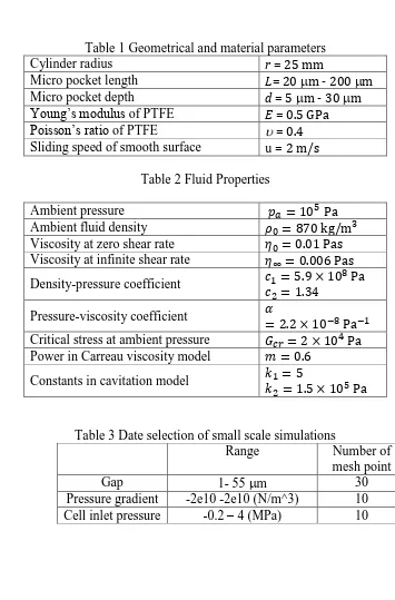
Table 1 Geometrical and material parameters 2
Cylinder radius r = 25 mm
Micro pocket length L= 20 m - 200 m Micro pocket depth d = 5 m - 30 m
Young’s modulus of PTFE E = 0.5 GPa
Poisson’s ratio of PTFE = 0.4
Sliding speed of smooth surface u= 2 m/s
[image:18.595.113.468.77.616.2]3
Table 2 Fluid Properties 4
5
Ambient pressure Pa
Ambient fluid density kg m Viscosity at zero shear rate 0.01 Pas
Viscosity at infinite shear rate Pas
Density-pressure coefficient Pa
Pressure-viscosity coefficient
Pa
Critical stress at ambient pressure Pa
Power in Carreau viscosity model
Constants in cavitation model
Pa
6 7
Table 3 Date selection of small scale simulations 8
Range Number of mesh point Gap 1- 55 m 30 Pressure gradient -2e10 -2e10 (N/m^3) 10 Cell inlet pressure -0.2 – 4 (MPa) 10 9
18 1
2 3
(a) (b)
4
Fig. 1 (a) Global geometry of a cylinder bearing in line contact, (b) micro pocket geometry of a 5
unit cell on the stationary wall surface (side length AE FG HB , EF GH 6
. ) 7
8 9
19
Fig. 2 Shear-thinning and piezo-viscous fluid property
1 2 3 4
[image:20.595.165.422.163.336.2]5 6
Fig. 3 Variations of the density fraction against fluid pressure described by hyperbolic tangent
7
function
20 1
2
(a)
3
(b)
4
(c)
21
Fig. 4 Mesh sensitivity analysis on smooth surface: (a) relative errors in the large-scale pressure
1
and mass flow rate using the solution of the finest mesh (960) as reference, (b) the large-scale
2
pressure distributions, and (c) enlarged local pressure details of figure (b)
22
a)
1
b)
2
c)
23
d)
[image:24.595.69.509.104.263.2]1
Fig. 5 Friction coefficient against ratio (d/L) (left) and the minimum film thickness against cell
2
depth (d) (right); a) Newtonian; b) Peizo-viscous; c) Shear-thinning; d) Shear-thinning &
Piezo-3
viscous
4
24
a) b)
1
25
c) d)
1
[image:26.595.47.350.112.532.2]2 3
Fig. 6 Newtonian solutions: (a) pressure and viscosity fraction, (b) film thickness (textured
4
surface with optimal parameters compared to smooth surface), (c) small scale pressure and (d)
5
density fraction variations at different locations convergent zone in the large
6
scale geometry
26 1
a) b)
2
[image:27.595.48.348.110.530.2]
3
Fig. 7 Shear-thinning solutions: (a) pressure and viscosity, (b) film thickness (textured surface
4
with optimal parameters compared to smooth surface; the arrow shows location of the
5
minimum film thickness)
27
a) b)
1
[image:28.595.45.336.110.513.2]2
Fig. 8 Shear-thinning and piezo-viscous solutions: (a) pressure and viscosity, (b) film thickness
3
(textured surface with optimal parameters compared to smooth surface; the arrow shows
4
location of the minimum film thickness)