Detection of Solvents using a Distributed Fibre Optic Sensor
Alistair MacLean, Chris Moran, Walter Johnstone, Brian Culshaw, Dan Marsh, Paul
Parker.
A fibre optic sensor that is capable of distributed detection of liquid solvents is presented.
Sensor interrogation using Optical Time Domain Reflectometry (OTDR) provides the
capability of locating solvent spills to a precision of ± 2 m over a total sensor length that may
extend to 20 km.
Introduction: In this Letter an optical fibre sensor capable of making fully distributed measurements of a wide range of solvents is identified. Microbending principles have been
used to develop the sensor such that it responds on contact with liquid solvents, typically
within 30 seconds of exposure. The sensor incorporates a swelling polymer and optical fibre
components that are readily available in the optical communications industry. A conventional
optical time domain reflectometry (OTDR) technique is utilised for sensor interrogation and
location of multiple spill events over a range of 20km. The sensor uses a low-power laser
source to perform the sensing function and due to its optical nature is intrinsically safe. The
operational characteristics of the sensor and the underlying technology utilised in its operation
are described. The swelling characteristics of the polymer material in a range of solvents and
experimental test results of prototype sensors are presented.
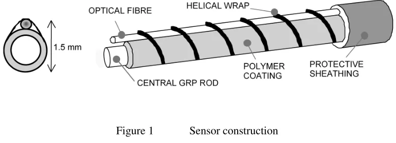
Sensor Design: The sensor structure consists of a central glass reinforced plastic strength
member 0.9 mm in diameter coated with a 100 µm thick silicone polymer (Dow Corning
Silastic rubber). A graded index multimode optical fibre (Plasma 62.5/125 graded index
PCVD fibre) is held against it by helically wrapping a 100 µm diameter Kevlar thread along
silicone polymer used. The swelling induced by the presence of the solvent causes the optical
fibre to be forced against the Kevlar thread, thus inducing periodic lateral deformation. The
optical fibre then experiences localised periodic microbending, causing light propagating in
the fibre to be coupled between the highest guided modes and nearest cladding modes where
it is attenuated. The period of the deformation determines the degree of attenuation that
occurs. It was found by Fields [1] that maximum mode coupling occurs when the deformation
is equal to a specific periodic spacing Λ, given by Equation 1.
Λ ∆ = 2
2
πa ( )
(1)
where a is the radius of the fibre core and ∆ is the maximum relative difference between
refractive indices of the core and cladding of the fibre. It was observed by Fields [1] and later
by Deimeer [2] that a multiple of this period could be used to induce mode coupling due to
the equal propagation constants of adjacent modes. For the multimode fibre used in the
sensor, Λ was calculated at approximately 1mm, thus it is possible to apply the Kevlar wrap
[image:2.595.104.493.480.621.2]with a pitch of 2, 3, & 4mm to cause mode coupling to occur during sensor activation.
Figure 1 Sensor construction
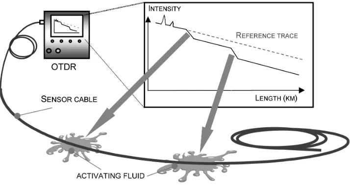
The sensor is interrogated using standard optical time domain reflectometry (OTDR)
principles. OTDR operates by sending a short pulse of light down the optical fibre and
monitoring the intensity of the light that is scattered back along the fibre. The OTDR trace
negative gradient for a fibre with uniform loss. Positions where the loss exceeds the inherent
[image:3.595.115.472.137.326.2]loss of the fibre appear as sections with increased gradient as is shown in Figure 2 schematic.
Figure 2 Schematic of sensor operation
Material analysis: In order to determine solvents suitable for detection by the sensor, the silicone used was subjected to a series of tests to estimate the swelling characteristics. It was
assumed that the swelling experienced by the silicone could be inferred from the degree of
solvent uptake. Small thin samples were weighed when dry and then placed either directly
into the solvent or suspended above it in a sealed container. The silicone samples were then
removed at regular intervals over a one-hour period to be weighed. It was observed from the
experiment that the maximum solvent uptake was achieved typically within 30 seconds when
the samples were placed directly into the solvents. Maximum solvent uptake was achieved
typically within 1 hour for samples suspended in the solvent vapour. Figure 3 demonstrates
the significant difference in solvent uptake for silicone samples placed directly into the
solvent and suspended in the vapour. From previous sensor work using swelling hydrogels [3]
it was observed that a weight increase of more than 65% was sufficient to cause a swelling
capable of inducing a force on the optical fibre in the sensor. Using this criterion, the
tested in liquid form, with the exception of acetone. The volatile vapours of chloroform,
petroleum ether, cyclohexane, toluene and dichloromethane induced a weight increase that
should also be readily detected since the fluid uptake values exceed the 65% threshold.
Neither methyl-ethyl-ketone nor acetone in vapour form induced a solvent uptake value that
[image:4.595.93.505.197.437.2]would be detected using silicone in the current sensor design.
Figure 3 Swelling of silicone suspended above and immersed in solvents
Prototype sensor testing: Using the materials knowledge from the above tests, several
prototype sensors were manufactured with the assistance of Pinacl Communications using the
silicone described in the preceding section and a 62.5/125 graded index multimode fibre. The
optical fibre was coated with Hytrel, a chemically resistant material incorporated to prevent
damage to the outer acrylate layer. The central GRP rod was coated with the silicone to a
thickness of 100 µm by drawing it through a silicone solution and curing it at an elevated
temperature in excess of 150°C. The Kevlar was wrapped over the coated GRP rod and
optical fibre with a pitch of 3mm, thus easing the precision wrapping requirements during
manufacturing. It was observed that the wrapping procedure caused no significant increase in
the inherent 3 dB/km loss of the fibre due to the buffering effect of the Hytrel. The prototype
sensors were evaluated using a commercially available Nortech PC-driven OTDR unit 0 50 100 150 200 250 300 350 400
Methy Ethyl Ketone
Toluene
Cyclohexane Chloroform
Petroleum ether
Acetone
Dichloromethane
Solvent uptake (pph)
Immersed in solvent
operating at an interrogation wavelength of 850nm with 20ns pulse widths. A 25m section of
prototype sensor was fusion spliced onto a 50m length of standard optical fibre at either side
to eliminate the effects of the near end dead zone and Fresnel reflection at the far end of the
fibre. Testing on the prototypes was conducted by capturing a reference OTDR trace of the
sensor in its dry state and comparing this with a trace of the sensor experiencing solvent
exposure over a 1 metre long section. The loss induced by the swollen silicone when exposed
to chloroform induced a 0.12 dB loss in the optical fibre as shown in Figure 4. The location of
the chloroform exposure can be readily identified as the position where the reference and
[image:5.595.91.510.290.623.2]activated traces deviate; corresponding to a position 61m along the total fibre length.
Figure 4 OTDR trace of 1m-long chloroform exposure located 61m along the fibre
In addition to the identification of chloroform, the sensor was also utilised to locate exposure
to toluene in a manner identical to the initial test. As can be seen from the deviation of the
that induced by chloroform, suggesting that the swelling results shown in Figure 3 are a good
indicator of the expected loss induced in the sensor when exposed to a particular solvent. To
conclude the tests, the solvents were allowed to fully evaporate from the exposed sensors.
When the silicone returned to its dry non-swollen state it was observed that the attenuation of
the sensor sections under test had returned to a level similar to the value prior to testing.
Subsequent repeat tests demonstrated that it was possible to perform multiple measurements
[image:6.595.91.509.243.573.2]on the same section of exposed sensor without any observed drop in sensitivity.
Figure 5 OTDR trace of 1m-long toluene exposure located 58m along the fibre
Conclusions: In this paper we have described a fibre optic sensor capable of the distributed
detection and location of liquid solvent spills. It has been demonstrated that the sensor is
capable of locating the presence of 1m lengths of both chloroform and toluene in liquid form due to the swelling of the silicone polymer. Additional fluids or gases may be detected by
incorporating an alternative material into the sensor that experiences swelling in their
approximately 3dB/km, which corresponds to a total sensing range less than 3.5km assuming
a dynamic range of 20dB for the OTDR. It is possible to increase the potential range to 20km
by shifting to an interrogation wavelength of 1310nm, where the inherent fibre loss is
0.5dB/km, assuming a similar OTDR dynamic range at this wavelength. The sensor is well
suited to applications where detection of solvent spills is required over extended areas where
point sensors could prove costly. It is particularly suited to environments where there is a high
risk of explosion. The distributed measurement capability provides effective monitoring and
rapid location of spills in large oil refineries, chemical plants or extensive pipeline networks.
Acknowledgements
EPSRC and DTI are thanked for their support of this work through the ‘DISH’ LINK scheme.
The contributions of Pinacl Communications, SDA Protec and OptoSci are also gratefully
acknowledged.
References
1. FIELDS J.N.: ‘Attenuation of a parabolic index fibre with periodic bends’, App. Phys.
Lett., 1979, Vol. 36, pp 779-801.
2. DIEMEER M.B.J. and TROMMEL E.S.: ‘Fibre optic sensors: Sensitivity as a function of
distortion wavelength’, Opt. Lett., June 1984, Vol. 9, (6), pp 260-262.
3. MICHIE W.C. et al,: ‘Optical fibre grout flow monitor for post tensioned reinforced tendon
ducts’, Proc. 2nd European Conference on Smart Structures, 1994, SPIE Vol. 2361,
pp186-189.
Authors affiliations:
Alistair MacLean, Chris Moran, Walter Johnstone, Brian Culshaw, ( University of
Strathclyde, Glasgow G1 1XW, UK.). Corresponding email: [email protected]