Dynamic Safety Assessment of a Nonlinear Pumped-Storage Generating
System in a Transient Process
Huanhuan Li1,2, Diyi Chen1,2*, Ehsan Arzaghi3, Rouzbeh Abbassi3,7, Adem Kilicman4, Tomas Caraballo5, Edoardo Patelli6, Xiang Gao1,2, Beibei Xu1,2
1Institute of Water Resources and Hydropower Research, Northwest A&F University, Shaanxi Yangling 712100, P. R. China
2Key Laboratory of Agricultural Soil and Water Engineering in Arid and Semiarid Areas, Ministry of Education, Northwest A&F University, Shaanxi Yangling 712100, P. R. China
3National Centre of Maritime Engineering and Hydrodynamics, Australian Maritime College (AMC), University of Tasmania, Launceston, Tas, Australia
4Department of Mathematics, University Putra Malaysia, 43400 UPM, Serdang, Selangor, Malaysia 5Department of Ecuaciones Diferenciales & Analysis Numerical, University of Sevilla, Apdo Correos
1160, E-41080 Seville, Spain
6Institute for Risk and Uncertainty, University of Liverpool, Peach Street, Chadwick Building, Liverpool L69 7ZF, United Kingdom
7School of Engineering, Faculty of Science and Engineering, Macquarie University, Sydney, NSW, Australia
Corresponding author: Diyi Chen
Mailing Address: Institute of Water Resources and Hydropower Research, Northwest A&F University, Shaanxi Yangling 712100, China
Telephones: 086-181-6198-0277 E-mail: [email protected]
between two different closing laws, namely the separate mode only to include a guide vane and the linkage mode that includes a guide vane and a ball valve. We find that the most unfavorable condition of the generating system occurs in the final stage of the load rejection transient process. It is also demonstrated that there is no risk to the generating system with the linkage mode but the risk probability of the separate mode is 6 percent. The results obtained are in good agreement with the actual operation of hydropower stations. The developed framework may not only be adopted for the applications of the pumped-storage generating system with a reversible Francis turbine but serves as the basis for the safety assessment of various engineering applications.
Keywords: Pumped-storage generating system; Francis turbine; dynamic safety analysis; risk probability; transient process
1. Introduction
Pumped-storage generating system with a reversible Francis turbine (PSGS) performs as a nonlinear multi-purpose engineering equipment for power production and power consumption, enhancing the efficiency and reliability of electrical power systems [1-2]. Today, the average estimated growth rate of PSGS increases 10% annually in the world, with a total installed capacity of more than 100 GW [3-6]. Pumped-storage power stations are built to improve the maximum usage of thermal and nuclear power as well as to guarantee a high quality of powersupply [7].
PSGSs provide twenty-four switching modes such as start-up in pumping/generating condition switch to shut-down, start-up in pumping/generating condition switch to load rejection, and static switch to pumping condition due to the different demands of the electricity generation in hydropower stations [12-14]. This results in a substantial level of safety challenges such as vibration and water hammer pressure amplitudes in the penstock and draft tube [15-19]. From the operational principle of PSGSs, the above-mentioned safety challenges highlight the need for analyzing the S and inverted-S domains for the operation of pump mode, turbine mode, braking mode in the pumping/generating condition and reversed pump mode. For example, due to the decrease of the pump-turbine flow during the load rejection transient, the generating system can enter the reversed pump mode meaning that the pump-turbine runs in reverse [20]. This in turn causes a higher pump-turbine speed with respect to three different values of the pump-turbine flow. It is therefore considered a hazard, thus, requiring more attention in safety assessment of PSGSs.
system in real time. The static assessment has been widely investigated by previous researchers, while the application of the dynamic approach is relatively limited, mainly due to complexity of the method. Currently, there are copious research outcomes available on PSGSs mainly focusing on dimensional design, hydrological computation, transient simulation and fault diagnosis aspects. However, not many investigations aim at assessing the safety of these systems. Safety assessment of PSGSs aims to predict the failure probability of the system in static and/or dynamic processes enabling the improvement of operation reliability. This requires developing a sound methodology and evaluative standard for an advanced safety assessment, given the complexity of PSGS.
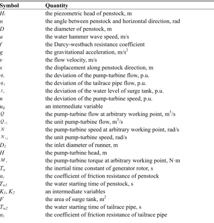
Table 1: Nomenclature of the pumped-storage generating system with a reversible Francis turbine Symbol Quantity
H1 the piezometric head of penstock, m
α the angle between penstock and horizontal direction, rad
D the diameter of penstock, m
a the water hammer wave speed, m/s
f the Darcy-westbach resistance coefficient g the gravitational acceleration, m/s2
v the flow velocity, m/s
x the displacement along penstock direction, m
1
q the deviation of the pump-turbine flow, p.u.
2
q the deviation of the tailrace pipe flow, p.u.
s
z the deviation of the water level of surge tank, p.u. n the deviation of the pump-turbine speed, p.u. uij an intermediate variable
Q the pump-turbine flow at arbitrary working point, m3/s
1 1
Q the unit pump-turbine flow, m3/s
N the pump-turbine speed at arbitrary working point, rad/s 1 1
N the unit pump-turbine speed, rad/s D1 the inlet diameter of runner, m
H the pump-turbine head, m
t
M the pump-turbine torque at arbitrary working point, N·m Ta the inertial time constant of generator rotor, s
α1 the coefficient of friction resistance of penstock Tw1 the water starting time of penstock, s
K1, K2 an intermediate variables F the area of surge tank, m2
Tw2 the water starting time of tailrace pipe, s
α2 the coefficient of friction resistance of tailrace pipe
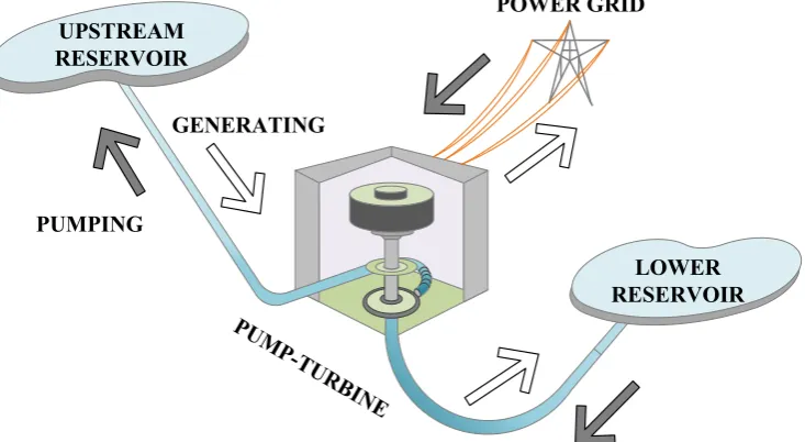
2. Pumped-storage generating system with a reversible Francis turbine
PSGS working mechanism is illustrated in Fig. 1.
UPSTREAM RESERVOIR
POWER GRID
LOWER RESERVOIR PUMPING
[image:6.595.117.484.155.356.2]GENERATING
Fig. 1. Schematic working mechanism of an PSGS. 2.1 PSGS Model
The basic dynamic behavior of an PSGS is expressed by the motion equation and continuity equation shown in Eq. (1) and (2). Using the method of characteristics performed in literatures [26-28], we further convert the Eq. (1) and (2) into the equations of characteristic lines. Additionally, the detailed boundary conditions of the studied PSGS model can also be found in references [26-28].
1
Motion equation of f ow: 0
2
l g H v v v fv v
x t x D
, (1)
2
1 1
Continuity equation of flow: H v H a v vsin 0
t x g x
penstock direction, respectively.
In this work, we focus on the transient safety analysis of the PSGS, thus a validated PSGS model presented in literatures [26-28] is introduced using the method of characteristics. Correspondingly, the validated PSGS model can be expressed as Eq. (3), and the detailed deducing steps are performed in the references [26-28].
1
1
11 13 14
2 2 22 23 31 32 41 44 0 0 0 0 0 0 0 s s dq dt q
u u u
dq q u u dt u u dz z
dt u u n
dn dt
, (3)
where q1, q2, zs and n are the deviations of the pump-turbine flow, the tailrace pipe flow, the water level of surge tank and the pump-turbine speed; uij (i = 1, 2, …, 4 and j = 1, 2, …, 4) denotes an intermediate variable, and it can be described as:
1 11 1 1 13 1 14 1
| | 2
( ) 1 2 ( ) w w w w
K Q H H
u
dQ
T Q N T
dN u T dQ H dN u dQ T Q N
dN
, (4)
2 22 2 23 2 | | 1 w w
K Q H
u T u T
31 32 Q u HF Q u HF (6) and 41 44 2 ( ) 2 t t a t t a dM M N dN u H dQ T Q N
dN
dM dQ
Q M
H dN dN
u
dQ
T Q N
dN
, (7)
where Q, N, H and Mt are the pump-turbine flow, the pump-turbine speed, the pump-turbine head and the pump-turbine torque at arbitrary working point, respectively; Tw1, Tw2, F and Ta are the water starting time of penstock, the water starting time of tailrace pipe, the area of surge tank and the inertial time constant of generator rotor, respectively; K1 and K2 are the intermediate variables,
4 2 1 1 1 11
K =2 D Q and 4 2 2 2 1 11
K =2 D Q . 1, 2, D1 and Q11 are the coefficient of friction resistance of tailrace pipe, the coefficient of friction resistance of penstock, the inlet diameter of runner and the unit pump-turbine flow, respectively.
2.2 100% Load Rejection Transient Process of PSGS
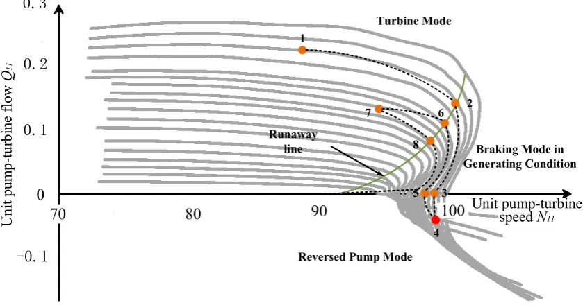
domain during this load rejection transient leading to an undesired situation where the generating system is operating with only one pump-turbine speed with respect to three different values of the pump-turbine flow. Here, as mentioned in the references. [1, 20], the inverted-S domain refers to the PSGS operates from the turbine mode to the reversed pump mode. The pump-turbine speed plays a critical role in the stability of PSGS as it directly influences the changes in the flow and water-hammer pressure in the penstock.
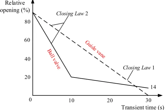
[image:9.595.133.468.471.573.2]Based on the above discussion, different closing laws of the closing devices are therefore designed to tackle the stability and safety challenges of PSGS during this transient process. Here, two different working modes of the closing devices, i.e., separate closing of guide vane (closing law 1) and linkage closing with guide vane and ball valve (closing law 2), are chosen from an existing PSGS in China [29-31]. The technical details of this station are listed in table 2.
Table 2: Technical details of the existing PSGS in China, adopted for safety assessment [29-31]
Parameter Value
Installed capacity 4×300 MW
Nominal speed of pump-turbine 500 rpm Water level of upstream reservoir in rejection transient 760 m
Water level of lower reservoir in rejection transient 205 m Nominal flow of single unit 70 m3/s
increasing rate in the change of hydraulic pressure.
20 40 60 80
0 10 20 30
14
Transient time (s) Relative
opening (%) Closing Law 2
Closing Law 1
[image:10.595.159.438.154.340.2]
Fig. 2. Different closing laws during the 100% load rejection transient in generating mode (closing law 1 of a guide vane and closing law 2 with a guide vane and a ball valve).
1
2
3
4 5
6 7
8 Runaway
line
80 90 100
0.3
70
Un
it
pu
m
p-tu
rb
in
e
fl
ow
Q
11
Unit pump-turbine
speed N11
0 0.20.2
0.1
-0.1
Turbine Mode
Braking Mode in Generating Condition
[image:11.595.89.509.116.336.2]Reversed Pump Mode
Fig. 3. Movement track of PSGS under the linkage closing law with a guide vane and a ball valve in inverted-S domain.
3. FDA method
Group 1 Group 2 R ef er enc e C oor di na te
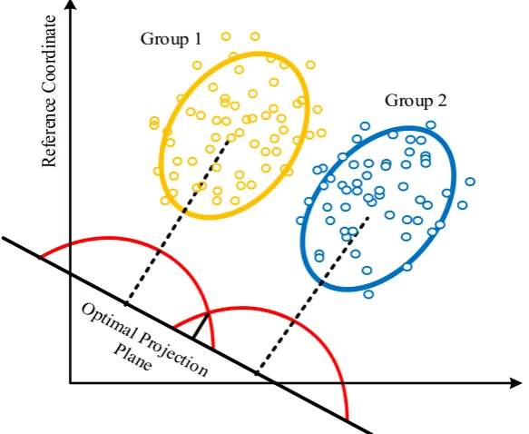
Fig. 4. Working principle of FDA.
For training groups Gi (i = 1, 2, ..., k), their corresponding mean matrix and covariance matrix of the samples from p-dimensional space are respectively μi and Σi. X, and u (u = u1, u2, ...) represents the linear discriminant coefficient that directly determines the discriminant rule. When a linear discriminant function u'X is considered, its mean and variance can be estimated as:
i i i i | DE ' ' E G '
' ' D G =
( ) | '
u X u X u μ
u X u X u u Σu, i = 1, 2, …, k. (8)
Supposing that b and e are the interclass and intraclass variances, respectively, then:
i i k 2 i 1 k i 1 ' ' ' e '
b ( )
u μ u μ
u Σu u Eu
where
11 21 p1
12 22 p2
1k 2k pk
u u ... u 1
u u ... u 1
1 1
=
... ... ... ... ...
k k
u u ... u 1
μ M1 and 2
3 1 ... μ μ M μ .
Subsequently, we can deduce k i i
i 1 =
M M μ μ and also simplify b as u Bu' . Here, = ( 1 ) k
B M I J M ,
and both I and J are unit matrices.
The objective function with regard to the linear discriminant coefficient u is therefore written as: '
( ) '
u u Bu
u Eu. (10)
To make ( )u reach to its unique maximum, there is an assumption that u Eu' =1 and
( ) ' - ' -1
u u Bu( u Eu ). The derivative of ( )u can be expressed as:
' =2 1- ' =0
' = ' ' -1 =0
u u Eu
u
u u u Eu
( )
( )
. (11)
We obtain Eq. (12) by simplifying Eq. (11), and Eq. (12) reveals that is the maximum value of '
u Bu and u is the eigenvector of E B1 .
1 '
( ) 0
u Bu
E B I u . (12)
Therefore, the eigenvector u = u1, u2, ... corresponding to the largest eigenvalue is estimated. Finally, the discriminant rule is obtained as:
1 1 2 2 p p
Initial analysis
Risk probability of the studied PSGS in the load rejection transient process
Dynamic safety level in the load rejection
transient process
D
yna
m
ic
as
se
ssm
ent
Start
End
Collect training data of PSGS in the load rejection transient process Understand working features of PSGS
in the load rejection transient process
Experimental data PSGS Model
Predicted data of PSGS in the load rejection transient process
Correction
FDA finds an optimal projection plane
Determine the classification of predicted data of PSGS at the
transient time ti
Estimate the safety level of
PSGS at the transient time ti
FDA Method
[image:14.595.126.474.106.548.2]Results of safety assessment
Fig. 5. Diagram of global methodology used in this paper.
4. Dynamic safety assessment of a transient PSGS
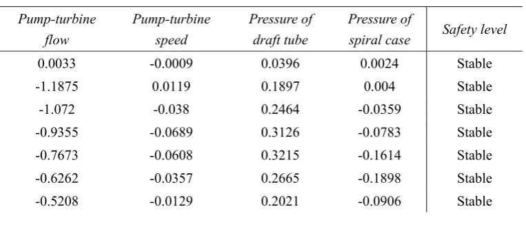
parameters considered for the risk assessment analysis are the flow rate and speed of the pump-turbine, pressure of the draft tube and the spiral case pressure. Four levels of safety composed of Stable, Medium, Unstable and High Risk are considered for the analysis from which one is assigned to each configuration of the training group. This assignment is based on the available statistical information as well as expert judgment, since there is no unified standard available to categorize the risk of a nonlinear PSGS. The properties of the four safety levels are given in table 3. To conduct the prediction process, thirty samples of PSGS operation parameters for both transient processes under separate closing law 1 and 2 are selected based on the validated PSGS model and experimental data presented in literatures [26-31], as listed in table 5.
Table 3: Properties of the four safety levels for an PSGS
Safety levels Properties
Stable PSGS operates normally
Medium PSGS vibrates slightly without failures
Unstable PSGS vibrates strongly with repairable failures High Risk PSGS cannot able to work with irreparable failures
Table 4: Training groups of a nonlinear PSGS for rejection transient from references [35-37] Relative Deviations for Variables of a Nonlinear PSGS (p.u.)
Pump-turbine flow
Pump-turbine speed
Pressure of draft tube
Pressure of
spiral case Safety level
0.0033 -0.0009 0.0396 0.0024 Stable
-1.1875 0.0119 0.1897 0.004 Stable
-1.072 -0.038 0.2464 -0.0359 Stable
-0.9355 -0.0689 0.3126 -0.0783 Stable
-0.7673 -0.0608 0.3215 -0.1614 Stable
-0.6262 -0.0357 0.2665 -0.1898 Stable
[image:15.595.108.490.577.748.2]-0.4773 0.0262 0.0088 0.025 Stable
-1.1394 0.076 0.1607 0.3356 Stable
-1.1247 0.0138 0.0638 0.1789 Stable
-1.0891 -0.0357 0.1282 0.011 Stable
-1.0239 -0.0646 0.2234 -0.0017 Stable
-0.9588 -0.0832 0.2234 -0.0059 Stable
-0.9937 -0.0936 0.2234 -0.0034 Stable
-0.8782 -0.1141 0.2234 -0.0059 Stable
-0.4045 0.0337 0.156 0.1324 Stable
-1.1697 0.0589 0.0667 0.0024 Stable
-1.0037 -0.0571 0.0514 0.0501 Stable
-0.0168 0.146 -0.0527 0.0814 Medium
-1.2053 0.1977 -0.0479 0.2114 Medium
-1.2426 0.0903 0.0579 0.1028 Medium
-0.5409 0.0965 -0.0438 0.1266 Medium
-0.6215 0.144 -0.0556 0.1719 Medium
-0.7092 0.1668 -0.094 0.2027 Medium
-0.8301 0.1649 -0.1372 0.2213 Medium
-0.9534 0.1402 -0.0603 0.2566 Medium
-1.0867 0.1131 -0.1697 0.3356 Medium
-1.2428 0.1287 0.1377 -0.0881 Medium
-0.075 0.2352 -0.0574 0.1307 Unstable
-0.1781 0.3241 -0.1372 0.2027 Unstable
-0.8425 0.3303 -0.2063 0.3159 Unstable
-1.1224 0.2681 -0.188 0.2776 Unstable
-1.0219 0.3151 -0.1923 0.308 Unstable
-0.1297 0.3012 -0.0756 0.1665 Unstable
-0.7417 0.2476 -0.1419 0.306 Unstable
-0.3316 0.3759 -0.1892 0.2624 High Risk
-0.4928 0.3983 -0.1987 0.2933 High Risk
-0.6867 0.384 -0.2631 0.3089 High Risk
-1.0386 0.3517 -0.1632 0.4118 High Risk
-0.2451 0.362 -0.1934 0.2241 High Risk
-0.8383 0.3721 -0.3196 0.3109 High Risk
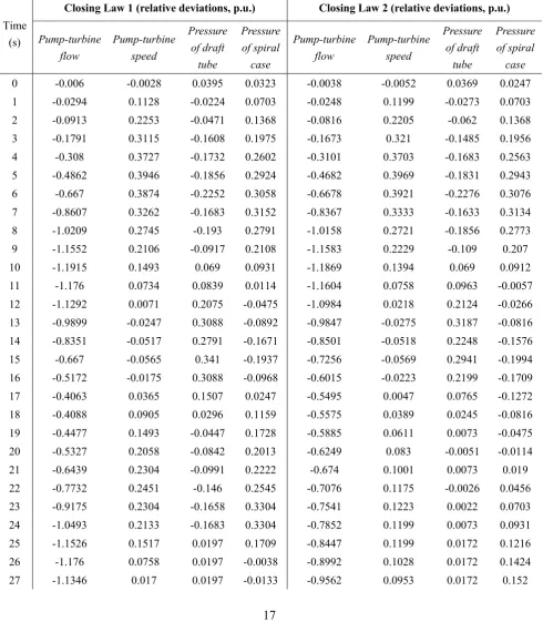
Table 5: Samples of nonlinear PSGS parameters for prediction of operation safety level under closing law 1 and 2 during 100% load rejection transient process [26-31]
Predicted Samples of a Nonlinear PSGS under Different Closing Laws
Time (s)
Closing Law 1 (relative deviations, p.u.) Closing Law 2 (relative deviations, p.u.)
Pump-turbine flow Pump-turbine speed Pressure of draft tube Pressure of spiral case Pump-turbine flow Pump-turbine speed Pressure of draft tube Pressure of spiral case
0 -0.006 -0.0028 0.0395 0.0323 -0.0038 -0.0052 0.0369 0.0247
1 -0.0294 0.1128 -0.0224 0.0703 -0.0248 0.1199 -0.0273 0.0703
2 -0.0913 0.2253 -0.0471 0.1368 -0.0816 0.2205 -0.062 0.1368
3 -0.1791 0.3115 -0.1608 0.1975 -0.1673 0.321 -0.1485 0.1956
4 -0.308 0.3727 -0.1732 0.2602 -0.3101 0.3703 -0.1683 0.2563
5 -0.4862 0.3946 -0.1856 0.2924 -0.4682 0.3969 -0.1831 0.2943
6 -0.667 0.3874 -0.2252 0.3058 -0.6678 0.3921 -0.2276 0.3076
7 -0.8607 0.3262 -0.1683 0.3152 -0.8367 0.3333 -0.1633 0.3134
8 -1.0209 0.2745 -0.193 0.2791 -1.0158 0.2721 -0.1856 0.2773
9 -1.1552 0.2106 -0.0917 0.2108 -1.1583 0.2229 -0.109 0.207
10 -1.1915 0.1493 0.069 0.0931 -1.1869 0.1394 0.069 0.0912
11 -1.176 0.0734 0.0839 0.0114 -1.1604 0.0758 0.0963 -0.0057
12 -1.1292 0.0071 0.2075 -0.0475 -1.0984 0.0218 0.2124 -0.0266
13 -0.9899 -0.0247 0.3088 -0.0892 -0.9847 -0.0275 0.3187 -0.0816
14 -0.8351 -0.0517 0.2791 -0.1671 -0.8501 -0.0518 0.2248 -0.1576
15 -0.667 -0.0565 0.341 -0.1937 -0.7256 -0.0569 0.2941 -0.1994
16 -0.5172 -0.0175 0.3088 -0.0968 -0.6015 -0.0223 0.2199 -0.1709
17 -0.4063 0.0365 0.1507 0.0247 -0.5495 0.0047 0.0765 -0.1272
18 -0.4088 0.0905 0.0296 0.1159 -0.5575 0.0389 0.0245 -0.0816
19 -0.4477 0.1493 -0.0447 0.1728 -0.5885 0.0611 0.0073 -0.0475
20 -0.5327 0.2058 -0.0842 0.2013 -0.6249 0.083 -0.0051 -0.0114
21 -0.6439 0.2304 -0.0991 0.2222 -0.674 0.1001 0.0073 0.019
22 -0.7732 0.2451 -0.146 0.2545 -0.7076 0.1175 -0.0026 0.0456
23 -0.9175 0.2304 -0.1658 0.3304 -0.7541 0.1223 0.0022 0.0703
24 -1.0493 0.2133 -0.1683 0.3304 -0.7852 0.1199 0.0073 0.0931
25 -1.1526 0.1517 0.0197 0.1709 -0.8447 0.1199 0.0172 0.1216
26 -1.176 0.0758 0.0197 -0.0038 -0.8992 0.1028 0.0172 0.1424
28 -1.0544 -0.0446 0.0197 -0.0019 -1.0028 0.0707 0.0172 0.1387
29 -0.9849 -0.0764 0.0197 -0.0437 -0.9818 0.0413 0.0172 0.112
30 -0.928 -0.0764 0.0197 -0.095 -0.9327 0.0047 0.0172 0.076
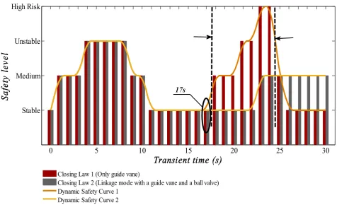
Upon training the FDA model the dynamic safety levels of the nonlinear PSGS are predicted regarding closing laws 1 and 2 during 100% load rejection transient. Fig. 6 presents the estimated safety level of the generating system throughout the transition period where dynamic safety curves are plotted to better illustrate the variable characteristics and the escalation of the system risk level.
0 5 10 15 20 25 30
Stable Medium Unstable High Risk
Transient time (s)
Sa
fet
y l
evel
Closing Law 1 (Only guide vane)
Closing Law 2 (Linkage mode with a guide vane and a ball valve) Dynamic Safety Curve 1
Dynamic Safety Curve 2
[image:18.595.58.535.307.597.2]17s
(a) (b)
Fig. 7. Comparison of estimated occurrence probability of each safety level with respect to closing law 1 and 2.
of including a ball valve in the closing process of the guide vane. That is, the ball valve can play a supporting role in system stabilization. The dynamic characteristic of PSGS during the transient process is then improved significantly by adopting an appropriate closing law of switch devices.
Fig. 7 presents the estimated occurrence probability of each risk level for PSGS load rejection process. A comparison of the results between the two closing laws clearly indicates that the high risk state in closing law 1 reaches 0.06 while this probability is zero for closing law 2. Furthermore, the probability of experiencing an unstable condition is approximately 0.23, when the generating system operates in closing law 1, while this is only 0.16 for closing law 2. The probability of encountering unexpected conditions in the PSGS operation is therefore close to 0.13, suggesting that a suitable linkage closing law that uses a guide vane, as well as taking advantage of a ball valve to support the system stability, is significantly beneficial for improving the dynamic characteristics of PSGSs during closing. It is worth mentioning that the obtained results are consistent with the engineering applications in literatures [26, 30-31, 35-39].
5. Discussion
6. Conclusions
Acknowledgements
This research is supported by the scientific research foundation of the National Natural Science Foundation of China--Outstanding Youth Foundation (51622906), National Natural Science Foundation of China (51479173), Fundamental Research Funds for the Central Universities (201304030577), Scientific research funds of Northwest A&F University (2013BSJJ095), Science Fund for Excellent Young Scholars from Northwest A&F University and Shaanxi Nova program (2016KJXX-55).
References
[1] Zuo ZG, Fan HG, Liu SH, Wu YL. S-shaped characteristics on the performance curves of pump-turbines in turbine mode - A review. Renew. Sust. Energ. Rev. 2016; 60: 836-851.
[2] Perez-Diaz JI, Sarasua JI, Wilhelmi JR. Contribution of a hydraulic short-circuit pumped-storage power plant to the load-frequency regulation of an isolated power system. Int. J. Electr. Power Energy Syst. 2014; 62: 199-211.
[3] Singh NP, Singh AK, Singh AK, Agnihotri P. Effects of thermophoresis on hydromagnetic mixed convection and mass transfer flow past a vertical permeable plate with variable suction and thermal radiation. Commun. Nonlinear Sci. Numer. Simul. 2011; 16: 2519-34.
[4] Zhang LK, Ma ZY, Wu QQ, Wang XN. Vibration analysis of coupled bending-torsional rotor-bearing system for hydraulic generating set with rub-impact under electromagnetic excitation. Arch. Appl. Mech. 2016; 86: 1665-1679.
Proc. 2016; 80: 414-428.
[6] Anilkumar TT, Simon SP, Padhy NP. Residential electricity cost minimization model through open well-pico turbine pumped storage system. Appl. Energy 2017; 195: 23-35.
[7] Kougias I, Szabo S. Pumped hydroelectric storage utilization assessment: Forerunner of renewable energy integration or Trojan horse? Energy 2017; 140: 318-329.
[8] Xu BB, Chen DY, Zhang H, Wang FF, Zhang XG, Wu YH. Hamiltonian model and dynamic analyses for a hydro-turbine governing system with fractional item and time-lag.Commun. Nonlinear Sci. Numer. Simul. 2017; 47: 35-47.
[9] Esmaeilpour M, Domairry G, Sadoughi N, Davodi AG. Homotopy Analysis Method for the heat transfer of a non-Newtonian fluid flow in an axisymmetric channel with a porous wall. Commun Nonlinear Sci Numer Simul 2010; 15: 2424-30.
[10] Weitzel T, Glock CH. Energy management for stationary electric energy storage systems: A systematic literature review. Eur. J. Oper. Res. 2018; 246: 582-606.
[11] Mohanpurkar M, Ouroua A, Hovsapian R, Luo YS, Singh M, Muijadi E, Gevorgian V, Donalek P. Real-time co-simulation of adjustable-speed pumped storage hydro for transient stability analysis. Electr. Pow. Syst. Res. 2018; 154: 276-286.
[12] Xu BB, Wang FF, Chen DY, Zhang H. Hamiltonian modeling of multi-hydro-turbine governing systems with sharing common penstock and dynamic analyses under shock load. Energ. Convers. Manage. 2016; 108: 478-487.
[14] Li B, Duan ZT, Wang X, Wu JZ. Loss-of-excitation analysis and protection for pumped-storage machines during starting. IET Renew. Power Gen. 2016; 10: 71-78.
[15] Mason DP, Hill DL. Invariant solution for an axisymmetric turbulent free jet using a conserved vector. Commun. Nonlinear Sci. Numer. Simul. 2013; 18: 1607-1622.
[16] Schmidt J, Kemmetmuller W, Kugi A. Modeling and static optimization of a variable speed pumped storage power plant. Renew. Energy 2017; 111: 38-51.
[17] Mennemann JF, Schmidt J, Kemmetmuller W, Kugi A. Simulation of wave effects in pumped-storage power plants using the spectral element method. AT-Autom. 2016; 64: 681-695.
[18] Vereide K, Svingen B, Nielsen TK, Lia L. The effect of surge tank throttling on governor stability, power control, and hydraulic transients in hydropower plants. IEEE Trans. Energy Convers. 2017; 32: 91-98.
[19] Vereide K, Lia L, Nielsen TK. Hydraulic scale modelling and thermodynamics of mass oscillations in closed surge tanks. J. Hydraul. Res. 2015; 53: 519-524.
[20] Li DY, Wang HJ, Qin YL, Wei XZ, Qin DQ. Numerical simulation of hysteresis characteristic in the hump region of a pump-turbine model. Renew. Energ. 2018; 115: 433-447.
[21] Patelli E, Govers Y, Broggi M, Gomes HM, Link M, Mottershead JE. Sensitivity or Bayesian model updating: a comparison of techniques using the DLR AIRMOD test data. Arch. Appl. Mech. 2017; 87: 905-925.
[22] Au SK, Patelli E. Rare event simulation in finite-infinite dimensional space. Reliab. Eng. Syst. Saf. 2016; 148; 67-77.
Consum. Electron. Mag. 2017; 6: 69-77.
[24] Ding XW, Chong X, Bao ZF, Xue Y, Zhang SH. Fuzzy Comprehensive Assessment Method Based on the Entropy Weight Method and Its Application in the Water Environmental Safety Evaluation of the Heshangshan Drinking Water Source Area, Three Gorges Reservoir Area, China. Water 2017; 9.
[25] Wrobel K, Montewka J, Kujala P. Towards the assessment of potential impact of unmanned vessels on maritime transportation safety. Reliab. Eng. Syst. Saf. 2017; 165: 155-169.
[26] Yang JD, Yang JB. Checking calculation and analysis on transient process of Huizhou pumped storage power plant in commissioning period. 1st ed. Wuhan: Wuhan University; 2010 [in Chinese]. [27] Yang JD, Zeng W, Yang WJ, Yao SW, Guo WC. Runaway stabilities of pump-turbines and its correlations with S characteristic curves. Transactions of the Chinese Society for Agricultural Machinery 2015; 4 [in Chinese]. Doi: 10.6041/j.issn.1000-1298.2015.04.010
[28] Zhang XX, Cheng YG, Xia LS, Yang JD, Qian ZD. Looping Dynamic Characteristics of a Pump-Turbine in the S-shaped Region During Runaway. J. Fluid Eng.-T. ASME 2016; 138.
[29] Hou CS, Cheng YG. Optimized closing procedures of wicket gate and ball valve for high head reversible pump-turbine unit. Journal of Wuhan University of Hydraulic and Electric Engineering 2005; 38 [in Chinese].
[30] Zhang C, Yang JD. Study on linkage closing rule between ball valve and guide vane in high head pumped storage power station. Water Resources and Power 2011; 29 [in Chinese].
26
[32] Li XW, Jiang CL, Tang J, Chen YJ, Yang DD, Chen ZX. A Fisher's Criterion-Based Linear Discriminant Analysis for Predicting the Critical Values of Coal and Gas Outbursts Using the Initial Gas Flow in a Borehole. Math. Probl. Eng. 2017.
[33] Van M, Kang HJ. Bearing Defect Classification Based on Individual Wavelet Local Fisher Discriminant Analysis with Particle Swarm Optimization. IEEE Trans. Ind. Inform. 2016; 12: 124-135. [34] Filisbino TA, Giraldi GA, Thomaz C. Ranking Tensor Subspaces in Weighted Multilinear Principal Component Analysis. Int. J. Pattern Recognit. Artif. Intell. 2017; 31.
[35] Wei SP. Simulation of hydraulic turbine regulating system. 1st ed. Wuhan: Huazhong University of Science and Technology Press; 2011 [in Chinese]. ISBN: 978-7-5609-7148-3
[36] Li JH, Zhu HF. Optimization on closing law of globe valve and guide blade after load rejection in Huizhou pumped storage units. Guangdong Electric Power 2012; 25 [in Chinese].
[37] Lin K. Measured results and simulation analysis of transient process of pumped storage unit in Huizhou. Guangdong Electric Power 2011; 24 [in Chinese].
[38] Chang JS. Transients of hydraulic machine installations. 1st ed. Beijing: China Higher Education Press; 2005 [in Chinese]. ISBN: 7-04-017647-5
![Table 2: Technical details of the existing PSGS in China, adopted for safety assessment [29-31]](https://thumb-us.123doks.com/thumbv2/123dok_us/1343465.88049/9.595.133.468.471.573/table-technical-details-existing-china-adopted-safety-assessment.webp)