White Rose Research Online URL for this paper:
http://eprints.whiterose.ac.uk/3613/
Article:
Gibbs, M.R.J. (2006) Materials optimization for magnetic MEMS. IEEE Transactions on
Magnetics, 42 (2). pp. 283-288. ISSN 0018-9464
https://doi.org/10.1109/TMAG.2007.893764
[email protected] https://eprints.whiterose.ac.uk/ Reuse
Unless indicated otherwise, fulltext items are protected by copyright with all rights reserved. The copyright exception in section 29 of the Copyright, Designs and Patents Act 1988 allows the making of a single copy solely for the purpose of non-commercial research or private study within the limits of fair dealing. The publisher or other rights-holder may allow further reproduction and re-use of this version - refer to the White Rose Research Online record for this item. Where records identify the publisher as the copyright holder, users can verify any specific terms of use on the publisher’s website.
Takedown
If you consider content in White Rose Research Online to be in breach of UK law, please notify us by
Materials Optimization for Magnetic MEMS
Mike R. J. Gibbs
Sheffield Centre for Advanced Magnetic Materials & Devices (SCAMMD), Department of Engineering Materials, University of Sheffield, Sheffield S1 3JD, U.K.
By highlighting magnetomechanical effects such as the1 -effect, and developing modeling code that integrates magnetoelasticity with microelectromechanical systems, it is shown that a simple cantilever system can have a sensitivity to mass loading at the attogram level. The requirements on the magnetoelastic materials for such devices are described, and progress towards achieving optimized ma-terial is reviewed. The possibility for deployment of such systems in security, healthcare, and bioscience is outlined.
Index Terms—Magnetic layered films, magnetostrictive devices, microelectromechanical devices.
I. INTRODUCTION
T
HERE are a number of examples in the literature where magnetic materials have been incorporated in to micro-electromechanical systems (MEMS) [1], [2]. From hereon we will use the diminutive MagMEMS when referring to MEMS incorporating magnetic material [3].The integration of magnetic components in to MEMS, MagMEMS, offers several key advantages over other MEMS technologies. Primary amongst these is the ability to develop wireless technology. In comparison to other MEMS technolo-gies, especially those incorporating piezoelectric materials, MagMEMS offer a higher power density, low performance degradation, fast response times, ease of fabrication and self test/self calibration functions [1], [3], [4]. A magnetic element may be interrogated by inductive coupling; the permeability or the resonant frequency of a structure containing the element being a function of stress, strain, pressure or other measurands due to the magnetoelastic properties of the magnetic material. The current macroscopic anti-theft sensors in stores rely on such a principle. This capability immediately opens up the possibility of applications in remote or hostile environments, and provides a mechanism for self-test and self-calibration [3]. Magnetic films have been successfully deposited on a wide range of substrates; conventional materials such as Si or GaAs, and also polymers (Kapton) and glass. MagMEMS structures should not be assumed to require standard Si microfabrica-tion, as other materials such as glasses or polyamides can be patterned using lithography or printing.
A range of proof-of-concept, or proof-of-principle, sensors and actuators based on MagMEMS have been demonstrated in recent years [1]–[6]. In particular the use of thin film magne-toelastic materials in MagMEMS has been considered [7], [8], but only in terms of measurement of saturation magnetostric-tion constant, and related properties such as the -effect. Op-timization of these properties for device applications, including the holistic aspects of the system performance, has not been addressed.
For the purposes of this discussion we will consider a can-tilever beam as the MEMS platform, to which we shall add
[image:2.594.348.508.213.296.2]func-Digital Object Identifier 10.1109/TMAG.2007.893764
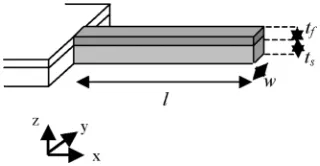
Fig. 1. Schematic illustration of the basic cantilever structure. The cantilever length is l, width w and thickness ist. The magnetic film and active layer coating the beam has thicknesst and the same lateral dimensions as the MEMS cantilever.
tionality by the introduction of magnetic material. A simple em-bodiment is sketched in Fig. 1.
In all that follows the MEMS platform will be assumed to be a typical tipless atomic force microscopy (AFM) cantilever currently in mass production. The reason behind this is that, in this exercise, we are highlighting the functionality achieved by the magnetic material, and wish to place no unusual constraints on the MEMS platform towards this goal.
Joule magnetostriction, the change in dimensions of a ferro-magnet on the application of an applied ferro-magnetic field, offers actuation in this context. If a magnetic field is applied in the direction in Fig. 1 then, for a material having a positive sat-uration magnetostriction, there will be a length increase along . In such a bimorph structure this will lead to deflection of the cantilever in , and contraction in . This gives mechan-ical actuation. Conversely, the mechanmechan-ical deflection of the tip of the cantilever in , will lead to a change in permeability of the magnetic film by the Villari effect (the inverse of the Joule effect). Thus a sensing function is possible.
There have been attempts at an analytical model of the bending of a MEMS cantilever beam under the influence of a coating layer of magnetostrictive material. Earlier work in this group using an adaptation of a finite element technique, demonstrated that these models were limiting cases of a more general response of such a system [9]. This has recently been more firmly established in this group using a finite element package (COMSOL), based on a multi-physics approach, that has allowed direct coupling of the magnetostriction tensor with the structural mechanics of a MEMS cantilever [10]. Agreement within a few percent was achieved with the various available analytical models, and important bending and curling modes have been demonstrated, as a function of width to length ratio
of the cantilever, not apparent from any earlier models. Also by modal analysis, it has been possible to establish physical attributes for the cantilever structure which will be necessary for mono-mode excitation, important for systems. At this stage ideal performance of the magnetic material has been assumed; that is magnetization by pure moment rotation of a single domain state. Further details are given in Section III. Future work, including the integration of micromagnetic modeling with MEMS models will be needed for more detailed analysis. Work on this is ongoing in the group, and will be reported elsewhere.
There is a very important magnetic characteristic missing from all of the previous modeling, the -effect, the field de-pendence of the Young’s modulus in highly magnetostrictive materials. We will discuss this in the context of a MagMEMS sensor.
In order to consider the significance of the -effect, we first investigate the deflection of a simple cantilever coated with magnetostrictive material. It has been shown [9] that a satisfac-tory empirical formula for the free end deflection, , of a can-tilever of length and width , and for a magnetic film of thick-ness and a substrate of thickness comprising the can-tilever, is given by
(1)
where and are the Young’s modulus and Poisson’s ratio of film and substrate, respectively. is the saturation mag-netostriction constant. Taking the following typical parameters for an AFM cantilever with a magnetostrictive film coating,
mm, mm, m, nm,
GPa, GPa, and
yields nm. Deflections of this order have been observed [11].
Because the magnetization is coupled to an applied strain via magnetostriction, there is more strain for a given load in an ap-plied field than in zero apap-plied fields. The total strain on the application of a load, , is made up of an elastic, , and a mag-netostrictive, , part, whence [12]
(2)
where is the saturation magnetization and the anisotropy constant. Here is the Young’s modulus in magnetic saturation.
If we define as the Young’s modulus after application of a field, then
(3)
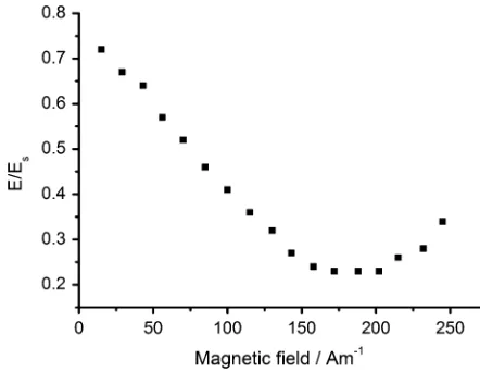
and the Young’s modulus is a function of magnetic field. Exper-imental data on bulk amorphous ferromagnetic ribbons demon-strating this effect are shown in Fig. 2. The effect reaches a max-imum when the anisotropy field, , is reached such that
[image:3.594.314.535.68.239.2](4)
Fig. 2. Ratio of Young’s modulus to saturation modulus versus applied field for METGLAS 2605SC ribbon field annealed to give close to pure 90 moment rotation on the application of the field. After [14].
We have previously demonstrated a proof-of-concept Mag-MEMS pressure sensor based on this phenomenon [13]. The res-onant frequency of a SiN microbridge coated in magnetoelastic material was shown to be a function of magnetic field. The ear-lier work [13] had not optimized the performance, and so should be taken as illustrative only. The significance of a -effect will now be developed further.
The importance of this result for MagMEMS is best seen by investigating the systems aspects of the problem. We will con-sider here a sensor that works on the principle of an active layer (polymeric for the sake of this discussion) coated on to the sur-face of a MagMEMS cantilever adsorbing a chemical species over its sensing surface. For simplicity, it is assumed that this adsorption increases the mass loading on the sensor, and thus translates into a change in density of the sensing layer (it is fur-ther assumed that the thickness of adsorbate is much less than the thickness of the sensing layer).
If is the fundamental resonant frequency of the compound cantilever sketched in Fig. 1, then
(5)
, is dependent on the cantilever’s thickness and length and on the properties of the material such as the Young’s mod-ulus and the density . For modeling purposes, can be taken as the average density of the beam components where more than one layer is involved. (5) is for a very simple cantilever and pinned at one edge. We will later consider in more detail the sensitivity which may be achieved, but move on first to a dis-cussion over the choice of magnetoelastic material that can be optimized for such applications.
II. MAGNETOELASTICMATERIALS
A. Principles
The Joule magnetostriction, the Villari effect, and the -ef-fect show the greatest response if the magnetization in the film rotates by 90 in the film plane [12]. In practical terms, this re-quires a material which can support a uniaxial anisotropy in a direction dictated by the sensor geometry. In order to maintain low power requirements in actuation the anisotropy field must also remain low, that is the anisotropy should be weak. We go on to consider the composition and preparation of films that can satisfy this criterion.
B. Composition Choices
[image:4.594.328.526.67.235.2]In terms of low anisotropy field, high permeability and useful levels of saturation magnetostriction the amorphous ferromag-nets based on around 80at% Fe are strong candidates. Around this composition the saturation magnetostriction constant is isotropic with a value of 20 ppm. When first introduced as rapidly solidified ribbon, the Fe-based amorphous ferromagnets showed that simple thermal treatments could be used to control both the magnitude and direction of the magnetic anisotropy, and that the piezomagnetic response followed this [14], [16]. More recently these results have been replicated for thin films of Fe-based amorphous ferromagnets [17], [18]. Fig. 3 shows that standard lift-off processing can produce structures with good geometrical definition. 500 nm thick films of the same com-position as METGLAS 2605SC (used as the target), grown on glass, can be produced with coercivities as low as 20 A/m and anisotropy fields as low as 100 A/m after a simple post-deposi-tion annealing treatment [18]. A thermal treatment at 400 C for 60 min in a vacuum of 10 Torr is sufficient to relieve stress remaining from the deposition process. The films are also ca-pable of responding to annealing in the presence of a magnetic field, a well established technique for the METGLAS alloys in ribbon form [16]. A field of 0.3 T applied in the film plane, for the same temperature and time as the stress relief anneal, gave a weak uniaxial anisotropy in the forming field direction [18]. Fig. 4 shows the domain pattern and hysteresis loop for a sample that has been field annealed after deposition.
Taking published data [19] for METGLAS 2605SC ( GPa, ppm), and the experimentally determined anisotropy field after field annealing, an estimate of
is obtained by use of (4).
Using an Fe B Si C target, Chiriac et al. [8] prepared amorphous ferromagnetic films on a polysilicon substrate, and determined basic magnetoelastic properties such as the saturation magnetostriction constant. From their tabulated data
was also determined from (4).
In terms of increasing values of the next set of alloys to consider are based on polycrystalline Fe-Co. The alloy series has been studied in bulk form for many years [20] with a bcc solid solution existing across the composition range of 0%–60% Co. The saturation magnetostriction constant peaks at the disordered equi-atomic composition, with a value of 150 ppm. Taking published data for the saturation magnetostriction constants of Fe Co [20], [21], an isotropic
Fig. 3. An AFM image of etched amorphous FeSiBC wires with nominal sep-aration 5m, wire width 10m and thickness 0.3m on a Corning 7059 glass substrate (after [17]).
Fig. 4. (a) Domain image of a field-annealed amorphous ferromagnetic film. (b) magneto-optic Kerr effect hysteresis loops (in two orthogonal directions) taken from the central region of image (a). The asymmetry is an instrumental artifact (after [18]).
[image:4.594.334.518.285.554.2]Fig. 5. Output from COMSOL simulation of the beam deflection (after [10]). (a) the deflection in z, (b) the deflection in y, showing the edge curling effects that can occur forw=l > 0:1, wherewis the cantilever width andlthe length. (Black highlights a greater deflection along the axis measured.)
layers, in order to achieve higher net magnetostriction constants for the films.
Whilst still in a more developmental stage, the Fe-Ga-Al al-loys (Galfenol) offer even higher of more than 200 ppm [23]. Thin films are being studied [24], and with more characteriza-tion and studies of alloying addicharacteriza-tions may offer an addicharacteriza-tional alloy series for MagMEMS.
Traditionally high of more than 500 ppm has come from alloys containing RE elements, the archetype being the Tb-Dy-Fe series (Terfenol). Hondaet al.[25], [26] were one of the first to research fabricating a cantilever device using magnetostrictive materials. From rare earth films of Tb-Fe and Sm-Fe, they developed a bimorph actuator found to have a large deflection even within a low magnetic field, but still higher than the anisotropy fields of the amorphous ferromagnets discussed above. The RE-containing materials are better suited for actuation than sensing.
In general, there are several alloy series which already, or with some further development, offer significant promise for MagMEMS. Further work is required on the production of con-trolled domain structure (leading to magnetization by pure mo-ment rotation), but the preliminary work, based on equivalent bulk alloy forms, shows considerable promise. In device appli-cations it may not always be the highest magnetostriction that is required, but rather the highest differential response at a given bias field (including zero field) that is important. This will be exemplified below.
III. SYSTEMMODELING
We have used COMSOL to model the simple cantilever system defined in Fig. 1, [10]. It is important to characterize the mechanical properties of the system, as this gives design criteria for a successful device. Assuming uniform rotation of the magnetization (Stoner-Wohlfarth behavior), and having coupled the full magnetostriction tensor to the MEMS module provided in the multi-physics package, the mechanical deflec-tion of the cantilever (see Fig. 1) has been studied. Fig. 5 shows the modes of deflection that can be observed. Provided the width to length ratio of the cantilever, , is less than 0.1 the cantilever is stiff in the y-direction.
It is also important to optimize the relative thickness of the layers in the overall cantilever structure, in order to ensure max-imum sensitivity to magnetostrictive stimulus. Fig. 6 shows a comparison of the tip deflection with an analytical model for the maximum deflection of a cantilever [27]. The FEM and an-alytical models agree very well, with the FEM allowing a wider range of analysis. Fig. 6 also gives an indication of the overall
Fig. 6. Deflection of a cantilever made with a glass or Kapton base layer as a function of the relative thickness of the active (magnetostrictive) layer to the base layer. The vertical lines illustrate the analytical solutions of [26]. The width to length ratio has not been optimized to reduce curling in this instance.
Fig. 7. Modal frequencies of a cantilever as a function of width to length ratio.
impact of the mechanical properties of the base material of the cantilever, by comparing data for glass and Kapton, a polyimide. A lower modulus base layer gives a greater deflection, but with more curling.
For a sensor system, the cantilever will be used under AC ex-citation. Either a rotating magnetic field can be applied, or more likely, a field pulse is used to excite the natural vibrational fre-quency (first bending mode) of the cantilever. Fig. 7 shows the modal response of the cantilever as a function of . These data have also been generated in the COMSOL environment. For , the first bending mode is well separated in frequency from other modes, and there will be little cantilever curling.
IV. MAGMEMS SYSTEM
These data give us sufficient confidence in the advanced FEM model, to proceed to the modeling of a MagMEMS system.
[image:5.594.304.553.66.230.2] [image:5.594.302.555.288.471.2]rather than piezomagnetic. This requires the ability to get an optical signal in and out of the sensor, and our goal is to demon-strate that with the wireless MagMEMS equivalent, a similar goal may be achievable. Ilic et al.[28] report attogram sensi-tivity, roughly equivalent to one strand of DNA added to the cantilever.
In order to highlight the practicalities of MagMEMS we will limit ourselves to MEMS cantilevers that are commercially available (tipless) for atomic force microscopy. Fabrication of such cantilevers is routine. For this model it is taken that a silicon wafer had a thermal oxide layer grown on its surface (SiO ), and on top of this again was grown 30 nm of low stress SiN by chemical vapor deposition. The properties of this SiN layer, GPa, kgm and are an average of values reported for this material. On top of this again was grown a 50 nm thick layer of METGLAS 2605SC by sputtering. This layer has properties GPa,
kgm and [19] assuming the film properties mimic the bulk form. We have already discussed in Section I how this structure can function as a sensor or actuator.
A standard bio-polymer, that may be functionalized to bind to a specific species (protein, toxin, antibody, etc.), has physical properties of GPa, kgm and
[29]. Such a film (say 100 nm thick) can be added to the mag-netic layer in the cantilever structure. Standard release proce-dures can then produce free standing cantilevers which resemble the schematic in Fig. 1.
In order to determine the mass loading sensitivity, we have run the model by converting added mass adsorbed by the bio-polymer in to the equivalent density change. On the scale of mass adsorption in which we are interested, the system dimen-sions can be assumed constant. This density change is then fed in to the calculation of resonant frequency. It is further assumed, for simplicity of calculation, that the mass is adsorbed as a uni-form layer over the cantilever surface. Fig. 8 is a plot of the shift in resonant frequency as a function of added mass, in steps of 1 attogram (equivalent to a 5 ng cm added to the cantilever surface).
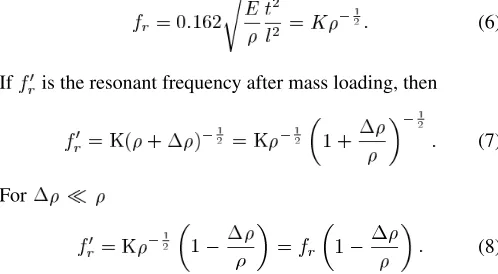
The validity of this highly linear response can be validated by further manipulation of (4) for the fundamental mode of the cantilever, , where
(6)
If is the resonant frequency after mass loading, then
(7)
For
(8)
For small added mass (change in density) the frequency shift is linear, and this is the response delivered from the model.
[image:6.594.302.553.65.256.2]The gradient of the line in Fig. 8 gives a sensitivity of ap-proximately 7.5 Hz/(ng cm ). The analytical model used here
Fig. 8. Shift in resonance frequency of a cantilever as a function of added mass. The agreement between the models is to be noted.
is equation [8] with a volume average for the Young’s modulus and density of the system. Again, there is excellent agreement between the analytical model and the simulation.
Such a small frequency shift would be difficult to detect in absolute terms. However, if we exploit the -effect set out above, and a high Q detector, then the resonant frequency will be a function of applied field through the field dependence of . Adsorption of material changes the density and hence the resonant frequency. The measurement of the added mass comes from the DC field necessary to bring the sensor back on to res-onance, which can be simply enabled. This makes for a very simple detection system.
The magnitude of the frequency shift at this level of sensi-tivity is such that we only need to shift the Young’s modulus by mPa to return to resonance. The field sensitivity, the gradient in Fig. 2, is the most important feature, and it is this differential response which needs to be optimized.
We have chosen in this exercise to demonstrate that Mag-MEMS can offer the same level of sensitivity as more conven-tional MEMS, but hasten to point out that in many application areas this high level of sensitivity may be inappropriate.
V. THENEXTSTEPS
As indicated above, there is still much to be gained in the study of MagMEMS from the optimization of the magnetic layers in terms of anisotropy control. Greater flexibility in modeling, and the ability to quantitatively correlate modeling with experiment, require a full micromagnetic implementation coupled to the MEMS code.
The simple cantilever modeled here could be replaced by a membrane, this only requiring the geometrical properties of the model to be adjusted. The wireless nature of stimulation and interrogation of such sensors offers deployment of a passive sensor in hostile environments.
[image:6.594.40.289.569.706.2]These challenges can be met with the resources available, and the potential for application in security, healthcare and bio-sci-ence is obvious.
VI. CONCLUSION
A full integration of magnetomechanical and magnetoelastic models has produced a powerful package for the design of MEMS incorporating magnetic materials. The FEM has been validated with analytical solutions wherever possible. From the wide range of possible magnetic materials for such applica-tions, it has been argued that high susceptibility and saturation magnetostriction constant, and low anisotropy field offer the best option.
ACKNOWLEDGMENT
Many useful discussions with J.S.Dean, T.Schrefl and, S.L. McArthur and E.W.Hill are acknowledged. The research pro-gram was supported in part by Sheffield University Enterprise Limited.
REFERENCES
[1] O. Cugat, J. Delamare, and G. Reyne, “Magnetic micro-actuators and systems (MAGMAS),” IEEE Trans Magn., vol. 39, no. 6, pp. 3607–3612, Nov. 2003.
[2] J. W. Judy, “Microelectromechanical systems (MEMS): Fabrication design and applications,”Smart Mater. Struct., vol. 10, pp. 1115–1134, 2001.
[3] M. R. J. Gibbs, E. W. Hill, and P. J. Wright, “Magnetic materials for MEMS applications,”J. Phys. D.: Appl. Phys., vol. 37, pp. R237–R244, 2004.
[4] I. J. Busch-Vishniac, “The case for magnetically-driven micro-actua-tors,”Sens. Actuators A: Phys., vol. 33, pp. 207–220, 1992. [5] I. Bolshakova, “Magnetic microsensors: Technology, properties,
appli-cations,”Sens. Actuators A: Phys., vol. 68, pp. 282–285, 1998. [6] P. I. Nikitin, M. V. Valeiko, A. Y. Toporov, A. M. Ghorbanzadeh, and
A. A. Beloglazov, “Deposition of thin ferromagnetic films for applica-tion in magnetic sensor microsystems,”Sens. Actuators A: Phys., vol. 68, pp. 442–446, 1998.
[7] H. Chiriac, M. Pletea, and E. Hristoforou, “Magnetoelastic character-ization of thin films dedicated to magnetomechanical microsensor ap-plications,”Sens. Actuators A: Phys., vol. 68, pp. 414–418, 1998. [8] H. Chiriac, M. Pletea, and E. Hristoforou, “Fe-based amorphous thin
film as a magnetoelastic sensor material,”Sens. Actuators A: Phys., vol. 81, pp. 166–169, 2000.
[9] R. Watts, M. R. J. Gibbs, W. J. Karl, and H. Szymczak, “Finite-element modelling of magnetostrictive bending of a coated cantilever,”Appl. Phys. Lett., vol. 70, pp. 2607–2609, 1997.
[10] J. Dean, M. R. J. Gibbs, and T. Schrefl, “Finite-element analysis on cantilever beams coated with magnetostrictive material,”IEEE Trans. Magn., vol. 42, no. 2, pp. 283–288, Feb. 2006.
[11] C. Body, G. Reyne, and G. Meunier, “Modeling of magnetostrictive thin films, application to a micromembrane,”J. Phys. III France, vol. 7, pp. 67–85, 1997.
[12] J. D. Livingston, “Magnetomechanical properties of amorphous metals,”Phys. Stat. Sol. A., vol. 70, pp. 591–596, 1997.
[13] M. R. J. Gibbs, C. Shearwood, J. L. Dancaster, P. E. M. Frere, and A. J. Jacobs-Cook, “Piezomagnetic tuning of a micromachined resonator,”
IEEE Trans. Magn., vol. 32, no. 5, pp. 4950–4952, Sep. 1996. [14] P. T. Squire and M. R. J. Gibbs, “1E effect in obliquely
field-an-nealed METGLAS®2605SC,”IEEE Trans. Magn., vol. 25, no. 5, pp.
3614–3616, Sep. 1989.
[15] C. A. Grimes, P. G. Stoyanov, D. Kouzoudis, and K. G. Ong, “Remote query pressure measurement using magnetoelastic sensors,”Rev. Sci. Instrum., vol. 70, pp. 4711–4714, 1999.
[16] A. P. Thomas and M. R. J. Gibbs, “Anisotropy and magnetostriction in metallic glasses,”J. Magn. Magn. Mater., vol. 103, pp. 97–110, 1992. [17] C. Shearwood, A. D. Mattingley, and M. R. J. Gibbs, “Growth and patterning of amorphous FeSiBC films,”J. Magn. Magn. Mater., vol. 162, pp. 147–154, 1996.
[18] M. Ali, R. Watts, W. J. Karl, and M. R. J. Gibbs, “The use of stress for the control of magnetic anisotropy in amorphous FeSiBC thin films: A magneto-optic study,”J. Magn. Magn. Mater., vol. 190, pp. 199–204, 1998.
[19] [Online]. Available: www.metglas.com. Accessed Oct. 17, 2006 [20] R. C. Hall, “Magnetic anisotropy and magnetostriction of ordered and
disordered cobalt-iron alloys,”J. Appl. Phys., vol. 31, pp. 157S–158S, 1960.
[21] [Online]. Available: www.vacuumschmelze.de Accessed Oct. 17, 2006
[22] M. D. Cooke, M. R. J. Gibbs, and R. F. Pettifer, “Sputter deposition of compositional gradient magnetostrictive FeCo based thin films,”J. Magn. Magn. Mater., vol. 237, pp. 175–180, 2001.
[23] A. E. Clarke, J. B. Restorff, M. Wun-Fogle, T. A. Lograsso, and D. L. Schlagel, “Magnetostrictive properties of body-centered cubic Fe-Ga and Fe-Ga-Al alloys,”IEEE Trans. Magn., vol. 36, no. 5, pp. 3238–3240, Sep. 2000.
[24] A. Butera, J. Gomez, J. L. Weston, and J. A. Barnard, “Growth and magnetic characterization of epitaxial Fe Ga /MgO (100) thin films,”J. Appl. Phys., vol. 98, p. 033901, 2005.
[25] T. Honda, K. I. Aria, and M. Yamaguchi, “Fabrication of magnetostric-tion actuators using rare-earth (Tb,Sm)-Fe thin films (invited),”J. Appl. Phys., vol. 76, pp. 6994–6999, 1994.
[26] T. Honda, K. I. Aria, and M. Yamaguchi, “Basic properties of magne-tostictive actuators using Tb-Fe and Sm-Fe thin films,”IEICE Trans. Electron., vol. 80, pp. 232–238, 1997.
[27] V. H. Guerrero and R. C. Wetherhold, “Strain and stress calculation in bulk magnetostrictive materials and thin films,”J. Magn. Magn. Mater., vol. 271, pp. 190–206, 2004.
[28] B. Ilic, H. G. Craighead, S. Krlov, W. Senaratne, C. Ober, and P. Neuzil, “Attogram detection using nanoelectromechanical oscillators,”J. Appl. Phys., vol. 95, pp. 3694–3703, 2004.
[29] S. L. McArthur, private communication.
![Fig. 3. An AFM image of etched amorphous FeSiBC wires with nominal sep-aration 5 �m, wire width 10 �m and thickness 0.3 �m on a Corning 7059 glasssubstrate (after [17]).](https://thumb-us.123doks.com/thumbv2/123dok_us/8084686.229776/4.594.328.526.67.235/etched-amorphous-fesibc-nominal-aration-thickness-corning-glasssubstrate.webp)
![Fig. 5. Output from COMSOL simulation of the beam deflection (after [10]).](https://thumb-us.123doks.com/thumbv2/123dok_us/8084686.229776/5.594.302.555.288.471/fig-output-comsol-simulation-beam-deection.webp)