IAC-13-C2.5.2
INFLATABLE SHAPE CHANGING COLONIES ASSEMBLING VERSATILE SMART SPACE STRUCTURES
Thomas Sinn
Advanced Space Concepts Laboratory, Mechanical and Aerospace Engineering, University of Strathclyde, United Kingdom, [email protected]
Daniel Hilbich*, Massimiliano Vasile†
Various plants have the ability to follow the sun with their flowers or leaves during the course of a day via a mechanism known as Heliotropism. This mechanism is characterized by the introduction of pressure gradients between neighbouring motor cells in the plant’s stem, enabling the stem to bend. By adapting this bio-inspired mechanism to mechanical systems, a new class of smart structures can be created. The overall structure is made up of a number of cellular colonies consisting of a central pressure source surrounded by multiple cells. After launch, the cellular arrays are deployed in space and are either preassembled or alternatively are attached together during their release or afterwards. A central pressure source is provided by a high-pressure storage unit with attached valve, which is routed to each colony and provides ingress gas flow into the system; a sequence of valve operations and cellular actuation then allows for any desired shape to be achieved within the constraints of the deployed array geometry. This smart structure consists of a three dimensional adaptable cellular array with fluid controlling Micro Electromechanical Systems (MEMS) components enabling the structure to change its global shape. The proposed MEMS components include microvalves, pressure sensors, mechanical interconnect structures, and electrical routing. This paper will also give an overview of the system architecture and shows the feasibility and shape changing capabilities of the proposed design with multibody dynamic simulations and on-ground prototype bench tests. Example applications of this lightweight shape changing structure are substructures for solar sails capable of steering through solar winds by altering the sails’ subjected area, as well as concentrators, mirrors, or communications antennas able to dynamically change their focal point.
I. ACRONYMS*†
C-NCP Conductive Nanocomposite Polymer
D Damping Matrix
Fact Actuation Force
Fext External Force
Finf Inflation Force
I/O Input / Output
K Stiffness Matrix
M Mass Matrix
MEMS Micro Electromechanical Systems
MWCNT Multiwalled Carbon Nanotube
NASA National Aeronautics and Space
Administration
NCP Nanocomposite Polymer
RC circuit Resistor–Capacitor circuit
PCB Printed Circuit Board
PDMS Polydimethysiloxane
SFU Simon Fraser University
* Microinstrumentation Laboratory, Simon Fraser
University, Burnaby, BC, Canada, [email protected]
† Advanced Space Concepts Laboratory, Mechanical
and Aerospace Engineering, University of Strathclyde, United Kingdom, [email protected]
II. INTRODUCTION
Further mass and volume can be decreased by enabling a space structure that is able to serve multiple purposes during its mission life. An example of this is a solar energy collector which could serve as a communication antenna by adjusting its shape and thereby its focal point. Extensive research has been undertaken in the field of structures that can change their properties by an external excitement [8]. For example, structural deformation could be induced through an applied electric field, or a change in stiffness could be achieved through an applied temperature change. Unfortunately, most of the adaptive materials available today require a constantly applied actuation force to obtain the desired shape which results in high power consumption. Other devices are bi-stable, using a short actuation impulse to switch between two different stable states. It is especially important that a space structure can stay in the deformed shape without the necessity of constantly driven actuation due to onboard power constraints.
Research at the University of Strathclyde in the development of such a deployable smart structure [9] borrows from nature’s concept of heliotropism [10], which is demonstrated by the head of a flower following the path of the sun during the day. This comparably rapid shape change in the plant is executed by motor cells in a flexible segment of the plants stem. These motor cells pump potassium ions into the tissue of neighbouring cells, increasing the cells torpor pressure. This pressure change alters the geometry of the cell and enables the plant to bend its flower head. This principle can be adapted to a mechanical structure capable of changing its shape by employing an array of cells, each with the capability of inflating and deflating independently. The resulting volume change of individual cells results in intercellular pressure gradients and a global shape change of the structure [11]. Since these structures are designed to be used in space with the excistance of only small gravitational forces, it is possible to design an extremely light, flexible structure with the capability of changing its shape with very low internal pressures in the order of a few hundred Pascal [1].
III. DESIGN
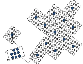
The proposed design is a light weight flexible structure with low storage volume and high deployed volume which has the ability to change its global shape in space. The global structure is made up of a number of similar self-sustaining and self-controlling cellular colonies deployed from a payload fairing, with only a small fraction of the volume of the deployed structure. There are various options to deploy and assemble these colonies to create the full structure in orbit. The option shown in Figure 1 is to deploy hundreds of these colonies in a single launch and inflate them with the
[image:2.612.315.542.185.343.2]desired cellular configurations. A construction robot can then assemble the global structure from the free flying colonies. The advantage of this approach is that the assembly robot can inspect the structures before assembly and use only the colonies which are fully functional. The assembly robot can also be used to simply reconfigure the structure and exchange broken components.
Figure 1: Schematic of deployment with the release of colonies from launcher and assembly via free-flying robot.
Another option (shown in Figure 2) would be to eject an assembly robot that has a storage unit filled with undeployed colonies. After the robot reaches the desired orbit, it will start releasing colonies one after another, letting them inflate and inspecting them for possible damage. The robot can hold on to the assembled structure, inspect the newly deployed colony and add it to the assembled structure.
Figure 2: Schematic of assembling structure via robot with colony storage
[image:2.612.359.503.501.611.2]III.I Modular Colonies
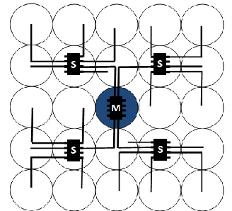
The main concept of the design is that a number of colonies, each composed of a number of individual cells, will be assembled together in space to form a global structure. Each colony is either a two dimensional plane or a three dimensional cube, made up of a 5x5 or a 5x5x5 array (x,y,z) of inflatable cells respectively, surrounding a central pressure source. The high pressure source is filled at the beginning of the mission and uses the gas stored in the pressure tank to inflate individual cells and change the overall shape of the structure until the tank is empty. To deflate a cell, gas is released into space via exit valves. Each cell is connected via MEMS valves either to neighbouring cells, to the central pressure source, or to the external environment. The cells are therefore inflated and deflated by redirecting the gas from the central source through the colony or releasing it to the environment. Figure 3 shows one smart element in a 3D structure; the central cell (blue) is connected to the pressure source and is surrounded by hyperelastic cells with six MEMS valves each. Neighbouring cells are fastened together with mechanical MEMS interconnects, allowing gas to flow through integrated microvalves. Electrical routing to a central controller and intercellular electrical interconnects are also present on each cell.
[image:3.612.84.266.391.572.2].
Figure 3: 3D realization of one cell connected to pressure source (centre) surrounded by inflatable cells connected via MEMS valves
III.II Control Architecture
In this system design, gas flow and electrical signals are routed throughout the cells in a colony enabling any configuration of inflated cells to be achieved. In this section we discuss the overall architectural details of a colony and the system as a whole which enables this functionality.
Electrical Routing
The first consideration is given to electrical routing and communication within a colony. It will be seen in later sections (see ‘Microvalves’ and ‘Pressure Sensors’ in Section III.IV) that each cell will require a number of electrical signals to control individual components within the cell, one signal per valve, and two signals per pressure sensor. We will also study various valve architectures available within a colony in Section III.II, and show that roughly 2.5 valves and 1 pressure sensor per cell will provide a suitable architecture. This means that we have, on average, 4.5 electrical connections per cell. If we route all cells in a 5x5 colony to a central controller, this will result in over 100 electrical I/O connections to the controller and over 200 intercellular electrical interconnects, which can be calculated by analysing Figure 4. To make these calculations, we can see that if each cell requires 4.5 routing signals all going to a central controller and there are 24 cells with this many signals (not including the central cell), then by multiplication the total number of I/O connections to the controller is over 100. The total number of intercellular connections (that is, the total number of connections across cell boundaries summed over the entire colony) is slightly less trivial to calculate. In Figure 4, a single coloured line is used to represent all routing signals from a given cell. The red ‘corner’ cell routing crosses four cell boundaries to arrive at the central cell, the green (cell below) crosses three, and blue crosses two. If the red routing is 4.5 signals and crosses 4 cell boundaries, then that is 18 intercellular connections total. The green and blue signals represent 13.5 and 9 such connections respectively. When all cells are accounted for, the total number of intercellular connections is over 200. The number of controller I/O connection requirements and intercellular interconnects becomes increasingly large as the colony size increases, which is quite prohibitive to the feasible colony size.
[image:3.612.357.515.516.667.2]The first improvement to the system’s electrical routing is to note that not all signals within a cell will need to be used at the same time. For example, if there are three valves in a cell, we can perform valve operations successively rather than concurrently. Similarly, the pressure sensor needs only to sense or deliver voltage, but never both. Finally, although it is true that valves and pressure sensors will need to work concurrently, for example during inflation, we can still take advantage of the fact that valve operations will require on the order of 10s to 100s of seconds, while pressure sensor operations are in the order of milliseconds. Thus, it will not impact system performance to intermittently switch from a valve operation to momentarily check on pressure. Thus, we can now reduce the number of active signals per cell to one. For example, even if there are a total of 4 routing signals in a cell, this can be reduced to 1 signal that is input to the microcontroller as long as a two bit control signal is added. In Figure 5, this two bit control signal is shown as two wires coming from the controller and fanning out to all cells, where it feeds a 1-to-4 demultiplexer to select one of the 4 electrical paths within the cell. Furthermore, we can make the allowance to have only one cell to be active at a time (the design can actually allow for more cells to active at a time; however for clarity of presentation, we reduce the number to one). This means that if there are n cells, we only require log2(n) signals from the controller to
feed a decoder which ultimately selects the active cell. As an example, in Figure 5 we see three cells with 4 active elements each coloured blue (valves, sensors, etc.). This would initially require a total of 12 signals to route, however with the addition of the demultiplexers (green) and the decoder, the controller is only required to output 5 signals.
Figure 5: Reduction of electrical routing via cell selection decoder and demultiplexing control signal.
Finally, another approach to minimise the intercellular routing would be to have multiple controllers in one colony which are only controlling
[image:4.612.346.510.164.313.2]neighbouring cells. This approach would require a master controller (which is located in the central cell in Figure 6) and multiple slave controllers distributed over the surrounding cells. The controller and software architecture should be set up such that the master status can be switched between the controllers in case of malfunction to keep the whole colony functional.
Figure 6: Controllers distributed over surface of colony
Connection Valves
The weight and complexity of the whole system is highly dependent on the amount of used valves in the system. The hard requirements are that every cell is accessible by the central pressure source by some path through neighbouring cells, and that any configuration of cells being inflated/deflated is achievable. There is an inherent trade-off in the design process: the approach that would use the fewest number of valves, thus reducing the mass and the complexity of the structure, is also the approach that would use the most gas or fluid since more complex valve operations are required, with more operations requiring that the gas be vented into the environment. On the other hand, the approach with a valve on each cell side, meaning each cell can exchange gas flow with all of its neighbours, makes the whole structure heavy and complex. A variety of connection valve architectures are shown in Figure 7.
Figure 7: Single path vs. tree path vs. full path (blue cell in centre: pressure source)
[image:4.612.90.303.490.642.2] [image:4.612.318.536.568.637.2]The amount of actuation and therefore the amount of used gas mass highly depends on the application and planned mission. For example if the mission is quite short, it may be better to use a design that requires fewer valves, since more of the gas would be expendable. On the other hand, a larger mission with many dynamic reconfigurations of the structure would require a large amount of gas; to minimize wasted gas in this case, it would be more feasible to increase the number of valves and complexity in the design. Essentially, each mission must minimize cost as a function of gas mass, valve mass, and complexity.
We now illustrate with an example. If the desired configuration is a checkerboard pattern, where each cell is in a state alternate to its neighbours, then the number of operations and the path of the gas will be different in each architecture. In Table 1, we show the number of valves required in each architecture, as well as the number of gas units required to achieve the checkerboard pattern due to inflation and deflation operations. Note that in this analysis, we assume the only outlet valve for the gas to escape to environment is at the central cell. Depending on the cost function (as yet undetermined) which operates based on the cost of gas and the number valves, it can be seen that there will be a large difference between the Single and Full architectures for this application.
Table 1: Required gas units and valves for each path design to achieve checkerboard pattern (without outlet valves at each cell)
Required: Single Tree Full
Valves 24 24 40
Gas Units 156 28 24
Outlet Valves
The amount of used gas can be further reduced by adding an outlet valve to each cell to release the gas into outer space. By adding these outlet valves, each cell can deflate by itself and is not required to deflate all the surrounding cells. The same analysis of the checkerboard pattern is presented in Table 2, except with outlet valves at each cell.
Table 2: Required gas units and valves for each path design to achieve checkerboard pattern (with outlet valves at each cell)
Required: Single Tree Full
Valves 48 48 64
Gas Units 24 20 18
As mentioned before, the added mass and complexity of the additional valves in contrast with the mass reduction of the required inflation gas must be addressed for each mission separately. We can see from a comparison in Table 1 and Table 2 that the extreme
case to minimize the number of valves and complexity requires 24 valves and 156 gas units, while minimizing gas use requires 64 valves and only 18 gas units.
III.III Inflatable Cell Design
The heliotrope principle makes use of a volumetric increase and decrease of certain cells, enabling an overall structure to change its global shape. In order to mimic this behaviour and achieve an increase/decrease in volume, a cell requires a membrane material that is highly flexible and elastic so that small pressure changes result in a significant increase in volume and also so that sufficient pressure exists within an inflated cell to self-deflate when exposed to the vacuum of space. Although the requirements for elasticity and flexibility of the cell membrane are crucial, it is also vitally important that the material selected can be incorporated with all other components into the overall design of the cell. Therefore, the ability of the material to be used in an overall fabrication process which allows for seamless integration all components into a single cell becomes a large design driver for the material. For this reason, and others which will be demonstrated as the remaining component details are described, we propose a silicone based elastomer such as polydimethylsiloxane (PDMS) to be spun into thin sheets, cured, and then bonded at the cell borders using well studied PDMS bonding techniques, such as oxygen plasma bonding, corona discharge, or adhesives [12]. This method allows for the integration of other MEMS components into the cell which are fabricated using
similar PDMS nanocomposite polymer (NCP)
techniques, such as hydrogel-based valves, mechanical interconnects and electrical routing components.
III.IV MEMS Devices
and applications often require the development of novel micro fabrication processes which are unique from those typically found in the microelectronics industry.
Perhaps the most prolific of all MEMS devices are the transducers: devices which convert measurable physical phenomena into electrical signals and vice versa (sensors and actuators, respectively). The last 30 years has seen a vast increase in the number of MEMS sensing devices suiting wide variety of sensing modalities [15], such as various chemical sensors, photometers, temperature sensors, mechanical and inertial force sensors, magnetic field sensors, air and gas flow sensors, etc. Though these MEMS sensors have traditionally enjoyed more focus than their actuator counterparts, more and more actuators are being developed, for example microfluidic pumps and valves, mechanical gears and motors, micro heaters, and electromagnetic field generators.
The benefits of a MEMS device versus its macro scale counterpart are typically reliability, cost, and functionality. Reliability is improved in part due to batch fabrication processes with highly controllable processing parameters resulting in high yield production capabilities. Another important aspect is that MEMS devices are often less susceptible to mechanical failure due little to no mechanical motion within the device, which can be seen for example in MEMS sensors [15]. Cost is also improved from batch fabrication, but is also greatly improved by a reduction in materials and power requirements. Improvements in functionality can generally only be analyzed in specific applications; however, some themes can be generally applied. Less variation at the micro scale often results in more accurate measurements, for example in a temperature sensor where a relatively large active measuring region will return the average of the temperatures within that region, while a smaller measuring region will more accurately show temperature variations invisible to the larger counterpart. Sensitivity is therefore increased at the micro scale, and other benefits can also be exploited, such as increased surface area to volume ratios.
Polymer MEMS devices in particular are increasing in popularity due to several advantages not found in traditional silicon devices, such as flexibility, opacity, biocompatibility, optical properties, and the ability to produce devices using large scale batch fabrication, among others [14]. Examples of these devices which are relevant to our design are discussed in further detail in the following sections.
Microvalves
In order to achieve a given cell configuration in our design, we require both a central pressure source to supply the gas flow as well as intercellular valves to direct the gas flow through to the desired cells; in this
section, we explore the microvalve component of the design using existing MEMS technology.
Microvalves are a growing application area within MEMS, and for the interested reader a comprehensive review of microvalve designs can be found in [16]. There are several microvalve variants which we may select from in order to meet our design requirements; for example magnetic, piezoelectric, thermal, or electrochemical valves may be selected according to the relative strengths in terms of power consumption, flow rate, capacity, size, reliability, etc. [16]. In our case, we desire a light weight, reliable valve which is normally closed (blocks fluid or gas flow without consuming power), with minimal restrictions on valve actuation frequency since we do not expect dynamic reconfigurations over very short periods of time. For this reason, we have selected a mechanically flexible diaphragm-based microvalve using a thermally responsive hydrogel actuator and a conductive nanocomposite polymer (C-NCP) heater element [17], which is illustrated in Figure 8. The C-NCP heaters that provide valve actuation are doped using tungsten nanoparticles, and require a single electrical I/O for the heater element. The valves measure 100-200μm in diameter, and were measured to deflect (increase in size) 100μm upon heating from room temperature (20°C) to 32°C over a period of 50-300 seconds. These valves provide performance metrics which meet our requirements; however, such a device has not been tested in space, and would need to be characterized under these conditions (particularly deflection characteristics at low temperatures). Additionally, since this is a thermally responsive valve design (Figure 8), the effectiveness would be limited to environments with relatively low temperature variations.
Figure 8: Thermally responsive hydrogel-based
microvalve [17] (used with permission)
[image:6.612.318.541.479.558.2](microvalves), Debiotech (implantable micropumps), Schwarzer Präzision (micropumps), and Bartels (micropumps).
Pressure Sensors
Each configuration of the cellular array will require either the inflation/deflation of several individual cells; these operations will likely require pressure sensory feedback to the controller in order to determine when a cell has been fully inflated or deflated. One simple approach would be to simply place a gas flow sensor at the main gas inlet location in order to track how much gas is inside the array. Given the desired number of filled or empty cells, the amount of gas required can be calculated and the total amount within the array can be adjusted accordingly. However, there are several practical considerations which forbid such a scheme. For example, there will be unavoidable leakage in the system. Since this occurs away from the inlet pressure source, it could not be tracked by the single flow sensor resulting in a discrepancy between the amount of gas within the system and the amount tracked by the controller. This is further compounded by the fact that the central flow sensor would itself have some error in its measurements, and any such error would propagate and increase over time with additional cell operations. The conditions within the cells would become increasingly different from what the controller would perceive. Finally, there will always be some unexpected pressure variations within the cells. It is important that no cell will over inflate, and that the controller can stop filling a given cell if a maximum pressure threshold is reached. For these reasons, we have determined that individual pressure sensors on each cell would be required. Ideally, each sensor (like the microvalve) would require minimal electrical routing and a fabrication scheme that would fit well within the overall cell fabrication process.
(a)
(b)
Figure 9: (a) Pressure sensor placed on outside of cell membrane. (b) With applied pressure, the distance between metallization layers will vary, altering the capacitance of the sensor.
A number of existing micromachined pressure sensor designs are available [18]; for our design, we have chosen a capacitive pressure sensor due to the relative increased pressure sensitivity and decrease temperature sensitivity when compared to other sensor types [18]. A diagram for this pressure sensor is given in Figure 9.
A voltage input to the capacitive sensor is routed to an output pin of the microcontroller. The microcontroller should also have an internal hardware resistor of a known value (or, an external resistor can be added), and an input pin for voltage sensing. The resistor and capacitor form an RC circuit with a time constant that varies according to the capacitance of the sensor. In order to determine the pressure, the controller sends periodic DC voltage outputs to the RC circuit, and measures the voltage across the capacitor through the voltage sensing input pin as the circuit relaxes. By measuring this relaxation voltage over time, the time constant can be calculated within the microcontroller, and thus the capacitance can be determined. This capacitance would then be compared to a pre-determined calibration table to find the pressure.
It should be noted that the pressure sensors are assumed to be required based on the aforementioned rationale. However, testing of a fabricated device should be conducted to test this assumption. Also, we assume that two pins are required on the microcontroller: one for voltage output, and one for voltage sensing. If a microcontroller can be found that can switch between these functions on a single pin, it would reduce the amount of electrical routing required. This is unlikely as voltage sources necessarily have low output impedances and voltage sensors have necessarily high input impedances.
Electrical Routing and Interconnects
As mentioned previously, the pressure sensor and microvalves in each cell will require routing to both input and output pins on the microcontroller. The architecture of the overall routing scheme in our design was Section III.II. However, the routing fabrication and integration is discussed here.
[image:7.612.82.310.521.665.2]A sample of these flexible routing lines is shown in Figure 10. The routing signals must travel across cells in order to reach the microcontroller, and are interconnected according to scheme given in [20].
Figure 10 Flexible NCP routing using multi-walled carbon nanotube doped PDMS [19]
Cell & Colony Mechanical Interconnects
The final component of the cells is a mechanical interconnect structure which allows neighbouring cells to be fastened together resulting in the modular assembly that we have proposed. Various examples of these mechanical interconnects, which also must allow fluid/gas flow, have been presented by the Microinstrumentation Laboratory at SFU, for example in [21-23]. The processing details are not repeated here; however the resulting structures can be seen in Figure 11 below.
Figure 11: Microfluidic board and assembled interconnect components [22] (used with permission)
Due to the fact that the colonies are free-standing assemblies with their own power system and data handling system, the colonies only have to be connected mechanically. The communication between different colonies is conducted wirelessly. The connections between the colonies therefore have to be semi rigid such that the actuation of the colonies results in the deformation of the whole structure. These connections should also be able to be easily released if the colony needs to be exchanged. A solution would be to use
magnetic connections between the colonies that has a permanent magnet on one side and on the other an electromagnet controlled by the colony. However, this system has two drawbacks: first, the electromagnet would necessarily be powered during all times that the colonies are connected, which may draw a prohibitive amount of power; second, magnets in space are subject to the influence of Earth’s magnetic field, which may cause undesired motion. A more simple approach would be to use the intercellular interconnects shown earlier in this section for the ‘inter-colonial’ interconnects as well. Alternatively, a hydrogel based system could be used, similar to that shown in the ‘Microvalves’ section; in this scheme, a hydrogel ‘male’ component one colony is heated (causing it to shrink in volume) and fitted into a ‘female’ component on another colony. When heating ceases, the hydrogel will expand, thus fastening the two colonies together. To detach, the hydrogel is heated once again.
IV SIMULATION & VALIDATION To prove the shape changing capabilities of the developed structure, a multi-body simulation and a simple bench test model has been created.
VII.I Simulation Set-up
To simulate the behaviour of the structure and to validate the shape changing capabilities, a multibody simulation was developed. Every cell in the simulation is modelled as a cube surrounded by beam elements. A mass point is located at each corner of the cube. Each beam element is able to transfer tension/compression, bending and torsional loads between the six degrees of freedom (DOF) nodes. Figure 12 shows the inflated spherical element surrounded by a cube made up of the 12 beam elements.
Figure 12: Single cell inside discretisation cube
[image:8.612.86.286.418.565.2] [image:8.612.365.510.504.601.2]
The equation of motion is solved continuously with variable forces. The forces are made up by the inflation force Finf, the actuation force Fact and the external force
Fext caused by external perturbations like variable
gravity, solar pressure or local impacts of micrometeoroids or space debris. All displacement, accelerations, velocities and forces are expressed in a Cartesian coordinate system.
Inflation
As an initial condition, all nodes are located in a centre point (e.g. the pressure storage) with an infinitesimal spacing between them. During inflation the pressure inside the cells increases which results in an equally applied force on the walls of the cell. This inflation force (Finf) can be distributed over the nodes of
[image:9.612.317.540.158.270.2]the cube to causing a displacement of the nodes and an introduced stress in the beam elements, mimicking the increasing tension of flexible cell wall during inflation. Figure 13 shows the qualitative displacement of the nodes of a 5x5x2 cell structure with an inflation time of 4 seconds and a linear gas inflow. It can be seen that the whole inflatable structure oscillates slightly after the inflation is complete. Each of the lines in this plot shows the displacement of each node in the structure over time.
Figure 13: Displacement of nodes during inflation in all directions (4sec inflation time)
The inflation force component in the equation of motion can also be used to implement a possible long-term leakage rate which needs to be compensated by actuation (continuous inflation).
Actuation
Based on the selected valve architecture, every cell can be deflated or further inflated at any given time. The in/deflation of specific cells causes the structure to deform in a specific way due to the pre-stressed nature
of the beam elements. Especially the coupling terms in the stiffness matrix enable the structure to obtain various different out of plane shapes after actuating cells which are in one plane or row. With this principle, countless different shapes can be obtained depending on the size of the array and the position of the actuated cells.
Figure 14: Double curved deformation of 5x5x2 array caused by deflation of top middle cells
[image:9.612.315.543.404.599.2]To demonstrate the shape changing principle, it was decided to deform a flat initial structure to obtain a double curved surface which can be seen in Figure 14. In order to obtain this shape the top middle row of cells in the x- and the y-direction were deflated by 25%. The actuation is applied directly after the overall inflation at 4 seconds.
Figure 15: Displacement of nodes during inflation in all directions (t<4s) and actuation (t>4s)
[image:9.612.83.280.423.566.2]IV.II Bench test
To validate the basic principle of global shape deformation due to local cell inflation and deflation a bench test model of an array of 5x5x2 cells was created. For the bench test model each cell was made of highly flexible latex with one in/outlet to release/add air. The inflated cells were then connected to each other over 105 rigid connections.
In a first test all of the cells of the array were inflated to roughly 10cm diameter. The interconnected cells were forming a semi rigid structure swinging in a low frequency when moved. Even after deflating random cells in this array, the structure stayed stable. This aspect is especially important by considering the danger of micrometeoroids puncturing single cells. Based on this result it can be said that the loss of a few cells will not necessarily cause a failure of the global structure.
[image:10.612.74.295.352.498.2]In order to validate the principle of deforming the structure by simply deflating certain cells, the entire middle row of the top array was deflated. It can be clearly seen in Figure 16 that after the deflation, the full array demonstrates a positive curved shape.
Figure 16: Deformation of bench test model and simulation after deflation of top centre row
The bench test model can be only used for a small number of cells with higher internal pressures then the full structure (consisting of thousands of cells) due to the fact that gravity is greatly affecting the deformation performance of the structure. Therefore, the results obtained by the bench test have to be seen a qualitative ones in order obtain an expected deformation direction to validate the simulation result.
V. APPLICATIONS
The proposed adaptive shape changing structure has various applications. One application could be as a substructure of a solar sail which would be deployed via inflation, obtaining a flat area for the solar particles to accelerate the spacecraft. Furthermore, the flat sail can then be bent to change the area subjected to the solar
wind and therefore make the spacecraft steerable with just the solar sail, and no need for additional thrusters.
Another application could be as a substructure for a concentrator or reflector of a spacecraft which can be deployed via inflation, taking advantage of the very low stored volume of the structure during launch. The focal point of the concentrator can then be adjusted with changing the curvature of the structure. This capability is required for applications like space based solar power were the solar panel collector has to point to one point in a geostationary orbit in order to have one stationary receiver of the energy on the Earth’s surface. Over the course of a day, the incoming light of the sun needs to be redirected by an adaptive mirror or concentrator on the surface of the solar panel collector.
An application for planetary or terrestrial rovers can be envisioned as well. The smart cellular structure could be actuated to move similar to a snake over any kind of terrain, even swim through water. Due to the fact that the actuation works with inflating and deflating the cells, the soft robot rover can actually squeeze through small openings giving it an advantage compared to conventional robots. Further applications of this soft robot can be in disaster relief, for example to search for survivors in a collapsed building after an earthquake.
VI. ACKNOWLEDMENTS
The authors wish to acknowledge members of the Microinstrumentation Laboratory at Simon Fraser University, Canada, for their contributions of images and design ideas. We also like to thank all the Strathclyde students that were involved in the REXUS experiment StrathSat-R and BEXUS experiment iSEDE for their continuous work on building experiments to prove the presented shape changing principle on a sounding rocket and stratospheric balloon.
VII. CONCLUSIONS
The structure developed in this paper enables the construction of large structures in space that are able to change their shape to fit different mission objectives. The global structure is assembled of multiple self sustaining colonies of inflatable cells capable of changing their shape through a bio-inspired principle. Each colony consists of a central pressure source and multiple MEMS valves connecting the surrounding highly flexible cells. Simulations and benchtests showed that by in- and deflating various cells, the shape of the global shape of the structure can be changed to the desired final configuration. The design and fabrication of the MEMS components are discussed, as well their influence on the overall system design. The microvalves are characterized by a hydrogel actuator driven by a
MEMS heater, which is composed of a
nanocomposite polymer (NCP). Flexible capacitive pressure sensors with thin film metallization layers are situated on each cell to provide sensory feedback to the system controller. A multiwalled carbon nanotube (MWCNT) based PDMS NCP fabrication process is used for flexible electrical routing integrated directly onto the cell wells. Each cell then consists of two thin sheets of thinly spun PDMS bonded together on their circumference enclosed by the MEMS valves with an attached pressure sensor, integrated electrical routing, and mechanical interconnect structures allowing for cells to be connected in order to form modular colonies. The paper also showed that to minimize the mass and complexity, the structure should be designed specifically for the mission (e.g. which cells need to be deflated, placement of valves).
REFERENCES
1J.R. Wertz, D.F. Everett, and J.J. Puschell, eds. Space
Mission Engineering: The New SMAD. Hawthorn, CA: Microcosm Press, 2011.
2C. Mangenot, J. Santiago-Prowald, K. van't klooster, ,
N. Fonseca, L. Scolamiero, F. Coromina, P. Angeletti, M. Politano, C. Elia, D. Schmitt, M. Wittig, F. Heliere, M. Arcioni, M. Petrozzi, M. Such Taboada "ESA Document: Large Reflector Antenna Working Group - Final
Report," Technical Note
TEC-EEA/2010.595/CM. Vol. 1, 2010.
3C. Mangenot, J. Santiago-Prowald, K. van ‘t klooster,
N. Fonseca, L. Scolamiero, F. Coromina, P. Angeletti, M. Politano, C. Elia, D. Schmitt, M. Wittig, F. Heliere, M. Arcioni, M. Petrozzi, M. Such Taboada “Large Reflector Antenna Working Group – Final Report” TEC-EEA/2010.595/CM, ESA, 2010
4L. Stiles, H. Schnaub “Electron Flux Deflection
Experiments with Coulomb Gossamer
Structures” AIAA-2012-1583, 13th AIAA Gossamer Systems Forum as part of 53rd Structures, Structural Dynamics, and Materials and Co-located Conferences, Honolulu, Hawaii, 23 - 26 April, 2012
5M.Gärdsback, G. Tibert, D.Izzo: Design considerations
and deployment simulations of spinning space webs. 48th AIAA/ASME/ASCE/AHS/ASC Structures, Structural Dynamics, and Materials Conference, Honolulu, HW, 23–26 April, 2007, AIAA-2007-1829.
6
T. Sinn, M. McRobb, A. Wujek, J. Skogby, f. Rogberg, J. Wang, M. Vasile, G. Tibert “Results of
REXUS12’s Suaineadh Experiment:
Deployment of a Web in Microgravity Conditions using Centrifugal Forces, IAC-12-A2.3.15, 63rd International Astronautical Congress, Naples, Italy, 1-5 October 2012.
7R.E. Freeland, G.D. Bilyeu, G.R. Veal and M.M.
Mikulas, "Inflatable Deployable Space Structures Technology Summary" IAF-98-I.5.01, 49th International Astronautical Congress, Melbourne, Australia, 28 September – 2 October, 1998.
8I. Chopra, "Review of state of art of smart structures
and integrated systems." AIAA journal 40.11 (2002): 2145-2187.
9T. Sinn, M. Vasile, G. Tibert “Design and
Development of Deployable Self-inflating Adaptive Membrane” AIAA-2012-1517, 13th AIAA Gossamer Systems Forum as part of 53rd Structures, Structural Dynamics, and Materials and Co-located Conferences, Honolulu, Hawaii, 23 - 26 April, 2012.
10E. B. Wilson, "The Heliotropism of Hydra", The
American Naturalist , Vol. 25, No. 293 (May, 1891), pp. 413-433.
11T. Sinn, M. Vasile “Bio-inspired Programmable
Matter for Space Applications” IAC-12-C2.5.1, 63rd International Astronautical Congress, Naples, Italy, 1-5 October, 2012.
12M. A. Eddings, M. A. Johnson, B. K. Gale
“Determining the optimal PDMS–PDMS bonding technique for microfluidic devices”
Journal of Micromechanics and
Microengineering, vol. 18, no. 6, 2008.
13
C. Richards Grayson, R. S. Shawgo, A. M. Johnson, N. T. Flynn, Y. Li, M. J. Cima, R. Langer “A BioMEMS review: MEMS technology for
physiologically integrated devices”
Proceedings of The IEEE - PIEEE , vol. 92, no. 1, pp. 6-21, 2004.
14C. Liu “Recent Developments in Polymer MEMS”
Advanced Materials Volume 19, Issue 22, pages 3783–3790, November, 2007.
15R. Bogue “MEMS Sensors: past present future”
Sensor Review, Vol. 27, No. 1. 2007, pp. 7-13.
16K. W. Oh, C. H. Ahn “A review of Microvalves” J.
17A. Li, A. Khosla, C. Drewbrook, B. L. Gray
“Fabrication and testing of thermally responsive hydrogel-based actuators using polymer heater elements for flexible microvalves” Proc. SPIE 7929, Microfluidics, BioMEMS, and Medical Microsystems IX, 79290G (February 14, 2011).
18W. P. Eaton, J. H. Smith “Micromachined pressure
sensors: review and recent developments” Proc. SPIE 3046, Smart Structures and Materials 1997: Smart Electronics and MEMS, 30 (June 19, 1997).
19A. Khosla, D. Hilbich, C. Drewbrook, D. Chung, B. L.
Gray “Large scale micropatterning of multi-walled carbon nanotube/polydimethylsiloxane nanocomposite polymer on highly flexible 12×24 inch substrates” Proc. SPIE 7926, Micromachining and Microfabrication Process Technology XVI, 79260L (February 15, 2011).
20T. Ueda, S. Jaffer, S. Westwood, B.L. Gray, "Design
of Electrical Interconnect for SU-8 Microfluidic Systems" Canadian Conference on Electrical and Computer Engineering, April 2007, pp.5-7.
21S. Westwood, S. Jaffer, B.L. Gray, "Enclosed SU-8
and PDMS microchannels with integrated interconnects for chip-to-chip and world-to-chip connections" Journal of Micromechanics and Microengineering, June 2008.
22
B.L. Gray, S.D. Collins, R.L. Smith, "Interlocking mechanical and fluidic interconnections for microfluidic circuit boards" Sensors and Actuators A, V12, April 2004, pp. 18-24.
23S. Jaffer and B.L. Gray, "Mechanically assembled

![Figure 8: Thermally responsive hydrogel-based microvalve [17] (used with permission)](https://thumb-us.123doks.com/thumbv2/123dok_us/1667859.120323/6.612.318.541.479.558/figure-thermally-responsive-hydrogel-based-microvalve-used-permission.webp)

![Figure 10 Flexible NCP routing using multi- walled carbon nanotube doped PDMS [19]](https://thumb-us.123doks.com/thumbv2/123dok_us/1667859.120323/8.612.365.510.504.601/figure-flexible-routing-using-multi-walled-carbon-nanotube.webp)


