City, University of London Institutional Repository
Citation
:
Petroulakis, N. E., Spanoudakis, G. and Askoxylakis, I. G. (2016). Patterns for
the design of secure and dependable software defined networks. Computer Networks,
109(1), pp. 39-49. doi: 10.1016/j.comnet.2016.06.028
This is the accepted version of the paper.
This version of the publication may differ from the final published
version.
Permanent repository link:
http://openaccess.city.ac.uk/15284/
Link to published version
:
http://dx.doi.org/10.1016/j.comnet.2016.06.028
Copyright and reuse:
City Research Online aims to make research
outputs of City, University of London available to a wider audience.
Copyright and Moral Rights remain with the author(s) and/or copyright
holders. URLs from City Research Online may be freely distributed and
linked to.
City Research Online: http://openaccess.city.ac.uk/ [email protected]
Patterns for the Design of Secure and Dependable SDN
Nikolaos E. Petroulakisa,b,∗, George Spanoudakisb, Ioannis G. Askoxylakisa
aInstitute of Computer Science, Foundation for Research and Technology-Hellas, Heraklion, Greece bDepartment of Computer Science, City University London, London, UK
Abstract
In an interconnected world, cyber and physical networks face a number of
chal-lenges that need to be resolved. These chalchal-lenges are mainly due to the nature and
complexity of interconnected systems and networks and their ability to support
hetero-geneous physical and cyber components simultaneously. The construction of complex
networks preserving security and dependability (S&D) properties is necessary to avoid
system vulnerabilities, which may occur in all the different layers of Software
De-fined Networks (SDN) architectures. In this paper, we present a model based approach
to support the design of secure and dependable SDN. This approach is based on
ex-ecutable patterns for designing networks able to guarantee S&D properties and can
be used in SDN networks. The design patterns express conditions that can guarantee
specific S&D properties and can be used to design networks that have these
proper-ties and manage them during their deployment. To evaluate our pattern approach, we
have implemented executable pattern instances, in a rule-based reasoning system, and
used them to design and verify wireless SDN networks with respect to availability and
confidentiality. To complete this work, we propose and evaluate an implementation
framework in which S&D patterns can be applied for the design and verification of
SDN networks.
Keywords: Design Patterns, SDN, Wireless Networks, Security, Dependability,
Drools
∗Corresponding author
1. Introduction
The design of complex system networks is of paramount importance due to their
increasing role in the implementation of Cyber-Physical Systems (CPS) and Software
Defined Networks (SDN) involving integrated ICT and physical components and
de-vices. However, the design of such networks adequate encounters difficulties which 5
need to be resolved. These difficulties stem from the highly distributed and
hetero-geneous nature of SDN and the extent of intelligence, dependability and security that
they need to demonstrate during their operation. The design and verification
meth-ods for developing secure and dependable system networks is necessary and should be
considered at design level to guarantee security and mitigate safety threats, on remote 10
monitored and managed networks. Especially, with the fast growing of SDN and the
integration with 5G network architectures [1], the design of networks enters in a new
era and makes necessary a careful investigation of the new security and dependability
risks, which have not been relevant in legacy systems. One of the challenges of future
networks is to develop SDN capabilities tailored to CPS and drive the reconfiguration 15
of these capabilities through network configuration specifications embedded in critical
infrastructures.
SDN allow network programmability and control to be decoupled from the
for-warding plane and the forfor-warding plane to be directly programmable by the control
plane. In this paper, we present a model driven approach to the design and verification 20
of secure and dependable SDN networks that is based on S&D network design patterns
(referred to asS&D patternsin the rest of this paper). These patterns can be used to
design and/or verify SDN network infrastructures and identify suitable paths and nodes
that can guarantee S&D properties. S&D patterns can be used to design SDN
infras-tructures, and determine also the type, location and connectivity of end nodes with 25
forwarding devices. At the control layer, S&D patterns can ensure secure
connectiv-ity between the controllers and the programmable switches. In this paper, we give a
detailed description of the scheme for specifying S&D patterns and their use for the
de-sign of S&D preserving SDN networks. The main contribution of the approach is that
as design patterns. In addition, S&D patterns can be used for the definition of optimal
paths which are able to guarantee S&D properties in deployed networks. A first
defi-nition of our pattern-based approach for designing reliable cyber-physical systems was
given in [2]. This paper extends the original approach by developing a pattern
frame-work in which we can evaluate and emulate S&D executable patterns on SDN-based 35
network designs. It also presents an application framework in which S&D patterns can
insert and modify flow rules through the controller to the programmable switches of
SDN infrastructures.
The remainder of this paper is organized as follows. In Section 2 an overview of
related work is presented. In Section 3, we present the schema of the pattern execu-40
tion form. In Section 4, we introduce abstract specification instances of patterns with
respect to confidentiality and availability encoded also to a rule-based reasoning
lan-guage. In Section 5, we propose an implementation framework in which S&D network
patterns can be applied in order to design and verify SDN network architectures. In
Section 6, we emulate our proposed network patterns for the design of wireless SDN-45
based network architectures able to provide security against physical layer attacks and
failures at design or at runtime in hostile environments. Finally, Section 7 provides
conclusions and future work.
2. Related Work
The main focus of network design relies on specification analysis, design, verifica-50
tion, and validation of systems that include hardware/software, data, procedures, and
facilities. Driven from software development methodology, Model-Driven
Engineer-ing (MDE) [3] can be used to analyze certain aspects of models, synthesize various
types of artifacts and design secure and dependable systems. An MDE framework for
architecting wireless networks is presented in [4]. The design of system is simplified 55
through the modelling of design patterns. MDE applies design patterns [5, 6] as
so-lutions for reusable designs and interactions of objects by the use of formal proven
properties[7]. The development of S&D patterns may benefit from the current
[8, 9, 10, 11, 12]. The concept of component-based architecture composition is mainly 60
applied on software components and service oriented architecture but it can be used
successfully for designing networks [13, 14]. Security workflow patterns, for service
compositions based on enabling reasoning engines such as Drools, are also described
in [15, 16]. Drools enabling reasoning appeared to be also an efficient rule engine
to represent our network workflow patterns. Workflow pattern for QoS aggregation 65
for web service composition have been proposed in [17]. In our approach, executable
workflow patterns are used for backward chaining for network compositions.
Especially with the softwarization of networks in SDN, design patterns can be
ap-plied in all the different layers of SDN architectures. One of major objectives of SDN
is to provide Quality of Services (QoS) and on-demand services [18]. Authors in [19] 70
present an end-to-end orchestration of IoT services using SDN-enabled edge nodes.
The construction of network topologies includes also the definition of network and
traffic patterns. Traffic engineering and patterns in SDN are presented in [20]. Flow
policy patterns as expressed by Frenetic languages, can generate flow rules able to be
installed in programmable switches of SDN networks [21]. In our approach, we can 75
provide paths as flow rules based on the security requirements. Design patterns can also
be used in northbound interface using RESTful API as proposed in [22]. Our proposed
pattern framework is able to interact with the controller using also the RESTful.
Fur-thermore, Service Function Chaining (SFC) [23] aims to provide end-to-end security in
SDN following security function compositions. Our approach is able to provide a step 80
forward by creating dynamic security chains following a backward chaining. Finally,
the concept of intent-based engineering in SDN appears to enforce security policies
[24] as proposed by our S&D patterns.
3. S&D Pattern Schema
The design and implementation of SDN infrastructures can be based on an archi-85
tectural framework where the network elements are integrated through patterns with
proven capability to enable the semantic interoperability, and to preserve end-to-end
instrument for designing, verifying and altering the topology of SDN networks, at
de-sign time or runtime. At dede-sign time, the procedure includes the definition of a dede-sign 90
problem and the required S&D property that needs to be guaranteed by the SDN to be
designed. In verification, an existing SDN network design (topology) and the required
S&D properties are provided, and patterns are applied to analyse the former and
estab-lish if the latter are satisfied. The analysis is based on checking if the topology of the
pattern matches the network design or some part of it and that the individual compo-95
nents that constitute the network with the particular topology have certain properties
that can guarantee end-to-end network level S&D properties. Finally, at runtime
pat-terns are applied to alter the topology and forwarding rules of an operational network
in order to ensure the satisfaction of S&D properties. The pattern specification schema
is defined as follows: 100
Definition 1. An S&D pattern schema is an abstract structure of specifying S&D
pat-tern which includes: (a) an abstract network topology, defining the control structure,
data flows of the components of an SDN, (b) constraints that should be satisfied by
the components of the network that are composed according to the structure of (a), (c)
the S&D property that the network topology in (a) guarantees, and (d) an execution 105
pattern rule.
The constituents (a)-(d) of the S&D pattern schema are discussed in more detail
below.
3.1. Pattern Topology
S&D patterns define generic ways of composing (i.e., establishing the connectivity 110
between) and configuring the different and heterogeneous components that may
ex-ist at all layers of the implementation stack of an SDN. The compositions defined by
S&D patterns can be both vertical and horizontal, i.e., they can involve components at
the same (horizontal) or different layers (vertical) layer in the reference architecture of
SDN. To do so, S&D patterns should encode abstract and generic component interac-115
tion and orchestration protocols, enhanced (if necessary) by transformations to ensure
(or need to be) composed. Furthermore, the component interaction and orchestration
protocols encoded by the patterns must have an evidenced ability (i.e., an ability proven
through formal verification or demonstrated through testing and/or operational moni-120
toring) to achieve a semantically viable interoperability between their components. In
SDN, components can be either hosts, forwarding devices or controllers. Paths may
include single step links between two edge nodes or link compositions with at least
one intermediate and two edge nodes.
AND
AND
OR
OR
XOR
[image:7.612.172.440.262.363.2]XOR
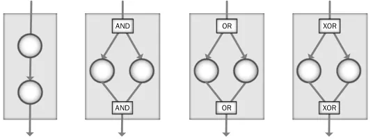
Figure 1: Basic SDN pattern logical topologies: (a) sequence (b) parallel-split-join (c) multi-choice-join (d) exclusive-choice-join
In our S&D patterns so far, we have focused on the logical architecture of the 125
network representing end-to-end connectivity, security and dependability. The basic
building blocks for forming logical network topologies are the same as those identified
for process workflows in [25]. As it can be seen in Figure 1 for example, the sequence
topology depicts the sequential composition of nodes in a network defines that a
pro-cess is enabled after the completion of a previous one. This topology appears as the 130
fundamental approach for building network process blocks and the diameter/tiers of a
network. The multi-choice-join topology (OR-OR) provides the execution of a process
to be diverged to two or more branches. This topology offers redundancy in network
structures. The parallel-split-join topology (AND-AND) allows the parallel split into
two or more branches. This topology is able to provide load-balance in network trans-135
missions. Finally, the exclusive-choice-join topology (XOR-XOR) diverges of a branch
into two or more exclusive branches. The latter topology can be used in networks in
3.2. Pattern Constraints
The S&D pattern schema includes also a set of constraints that should be satisfied 140
by the individual network components composed by the pattern and/or the component
composition as a whole. These constraints may represent functional requirements
re-garding such as the connectivity between two components and can be related to the type
of components (hardware/software). Different parameters such as the distance between
network nodes that is a topological constraint for a network may also be expressed 145
through S&D patterns constraints. For instance, in wired networks this connectivity
can be satisfied using suitable interfaces and cables. However, in wireless networks,
the connectivity is based on the coverage of each node and it can be classified into
deterministic and probabilistic models. Furthermore, the applications and services that
make use of the network are crucial factors on the design of a network as they can 150
affect the available resources such as computational power, available memory, storage
and networking capabilities. Other constraints which may be expressed as S&D pattern
schema constraints may refer to the quantity and type of nodes, interfaces per nodes,
cost and energy consumption.
3.3. Pattern S&D Properties 155
S&D design patterns specify SDN designs that guarantee given security
(confiden-tiality, integrity, availability) and dependability (reliability, safety and maintainability)
properties. The satisfiability of an S&D property can be defined by a Boolean value
(i.e. encryption enabled/disabled), an arithmetic measure (i.e. delay, encryption level)
or probability measure (i.e. reliability/uptime availability). It should be noted that 160
the composition of two components which preserve an S&D property does not
neces-sarily guarantee that the composition will also preserve the same property. However
in networks, it is important that properties are also guaranteed on the communication
medium. Attacks on wireless medium can also cause an attack on a system component.
Since, a medium such as a wireless link cannot be modified, in order to guarantee a se-165
curity property, the property should be satisfied at both the output of the source node
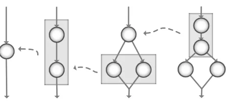
Figure 2: Stepwise Decomposition
S&D patterns can be used to recursively build component compositions or
decom-positions using forward or backward chaining respectively, as depicted in Figure 2.
Forward chaining is useful in verification and backward chaining can be used in in-170
ference. In forward chaining, the properties satisfied by componentsC1, ..Cnmay be
different from each other and different from the propertyProthat the composition
sat-isfies. WhenC1, ..,Cnare components that satisfy propertiesPro1, ..,Pronrespectively,
then the compositionCformed of these components can satisfyProwhen the following
implication can be proved: 175
When(C1satisfyPro1)∧(C2satisfyPro2)∧ · · · ∧(CnsatisfyPron)→CsatisfiesPro
On the other hand, backward chaining appears to be more important in system
design with respect to a required property. WhenC is required to satisfy a property
reqPro, then suitable componentsC1, ..,Cnshould be found to satisfyreqPro1, ..,reqPron:
reqPro(C)→reqPro1(C1)∧ · · · ∧reqPron(Cn)
180
As an example, let’s consider a sequential composition of two components:C→
C1∧C2. If a required property should be guaranteed by theC, the subcomponentsC1
andC2should satisfy the conditionreqPro1(C1)∧reqPro2(C2). If there are no atomic
components to guarantee the requiredreqPro1(C1)∧reqPro2(C2), a recursive
proce-dure is used in which successive (sub-) compositions are generated until the atomic 185
analyzed as follows:
reqPro1(C1)→reqPro11(C11)∧reqPro12(C12)
reqPro2(C2)→reqPro21(C21)∧reqPro22(C22)
· · · → until nodesC11,C12,C21,C22
that satisfyreqProare found
3.4. Pattern Rules
Once proven, relations between pattern component properties can be expressed as
production rules to enable reasoning. In implementing our approach, we have selected 190
Drools [26] to express S&D patterns as rules because this rule engine supports
back-ward and forback-ward chaining inference and verification by implementing and extending
the Rete algorithm [27]. Drools rules can encode the topology of a pattern and the
process of finding suitable component compositions in order to guarantee the required
property. Drools production rules are stored in the production memory and are used 195
to process data inserted in the working memory (Knowledge Base) as facts by pattern
matching. Each rule consists of two parts: thewhencondition and thethenactions.
When a network that matches the topology of an S&D pattern does not satisfy the
re-quired property, the pattern may be used to substitute, add or remove components from
it in order to satisfy the property. 200
A Drools rule that encodes an S&D pattern includes the inputs of the pattern’s
components, the type of composition and the required S&D property in Left Hand Side
(LHS). When the conditions in the LHS are satisfied, then the rule is fired to execute the
actions as described in its Right Hand Side (RHS). In the RHS, the new requirements
of the compositions or atomic components can be inserted, updated or deleted. 205
4. S&D Pattern Instances
In this section we present specifications of S&D patterns instances, which are able
to guarantee confidentiality and availability in network infrastructures based on the
pattern specification approach discussed in Section 3.
4.1. Link-to-link Confidentiality Pattern 210
Confidential transmission on the infrastructure layer focuses on keeping
following, we define an S&D pattern that can guarantee this property, calledlink-to-link
confidentiality pattern.
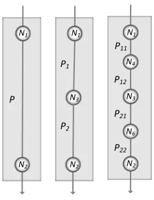
Pattern Topology: The topology of the link-to-link confidentiality network pattern
215
with two nodesN1andN2is sequential. This is expressed by pathPbetweenN1and
N2:P=Path(source=N1,destination=N2).Pmay be either an atomic link or path
composition. The decomposition phase (as shown in Figure 3) can be analyzed as
follows:P=Path(source=N1,destination=N2) =Path(source=N1,destination=
N3)∧Path(source=N3,destination=N2).
N1
N2
N1
N2
P1
P2
N3
N1
N2
N3
N4
N6
P11
P12
P21
P22
[image:11.612.249.361.275.420.2]P
Figure 3: Sequence Decomposition
220
Pattern Constraints:Further constraints of the link-to-link confidentiality pattern
re-late to the distance between edge nodes. A constraint of this type expresses that if the
maximum link range isr, the distance between edge nodes of a link-to-link
composi-tion should ber≥Distance(N1,N2).
Pattern S&D Property: Link-to-link encryption protects traffic flows from
monitor-225
ing since all data (payload and headers) are encrypted/decrypted in every hop. When
two nodesN1 andN2are connected following the sequence pattern, the path is
con-fidential when both nodes are able encrypt and to share encrypted data. This is
ex-pressed by the relation: Path(N1,N2,encryption=true)→Node(N1,encryption=
true)∧Node(N2,encryption=true).
230
Pattern Inference Rule: The confidential rule (Rule 1) encodes the sequence
and a path$Pwith source the$N1and destination the$N2(line 5). The constraint of
the pattern topology defines that the link range$rshould be less or equal to the distance
between$N1and$N2. The S&D property$reqProthat the pattern should guarantee 235
is presented inlines 6-7. When the topology constraint and the S&D property are not
satisfied the rule will enter in the RHS of the rule. In the RHS, a new node$N3should
be inserted between the$N1and$N2(lines 9-10). Moreover, two new paths $P1 and
$P2 (lines 11,14) and two new requirements $R1 and $R2 (lines 12-13,15-16) for these
paths will be inserted in the knowledge base. Finally, the rule will modify the require-240
ment of the satisfaction to true (line 17). The recursive procedure will complete when
the minimum number of nodes satisfy the distance constraint and therefore the S&D
requirement.
Rule 1: Inference Rule of Link-to-Link Confidentiality Pattern 1 r u l e ” Link−t o−l i n k C o n f i d e n t i a l i t y I n f e r e n c e R u l e ”
2 when
3 $N1 : Node ( $ i d 1 : i d , $p1 : p o s i t i o n , e n c r y p t i o n ==t r u e)
4 $N2 : Node ( $ i d 2 : i d , $p2 : p o s i t i o n , e n c r y p t i o n ==t r u e)
5 $P : P a t h ( s o u r c e ==$N1 , d e s t i n a t i o n ==$N2 , $ r : r a n g e , $d : d i s t a n c e , $ r<=$d )
6 $R : R e q u i r e m e n t ( p a t h == $P , p r o p e r t y . name==” E n c r y p t i o n ”,
7 $ r e q P r o : p r o p e r t y . v a l u e , s a t i s f i e d ==f a l s e)
8 t h e n
9 Node $N3 = new Node ( $ i d 1 + $ i d 2 ,new P o s i t i o n ( $N1 , $N2 ) ,t r u e) ;
10 i n s e r t( $N3 ) ;
11 P a t h $P1 = new P a t h ( $N1 , $N3 ) ; i n s e r t( $P1 ) ;
12 R1= new R e q u i r e m e n t ( $P1 ,new P r o p e r t y (” E n c r y p t i o n ”) , $ r ,f a l s e) ;
13 i n s e r t( R1 ) ;
14 P a t h $P2 = new P a t h ( $N3 , $N2 ) ; i n s e r t( $P2 ) ;
15 R2 = new R e q u i r e m e n t ( $P2 ,new P r o p e r t y (” E n c r y p t i o n ”) , $ r ,f a l s e) ;
16 i n s e r t( R2 ) ;
17 modify( $R ){s a t i s f i e d =t r u e};
18 end
Pattern Verification Rule:The second confidentiality rule (Rule 2) expresses the
ve-rification procedure in case of an existing SDN network design. The paths can be given 245
by the use of an algorithm such as the depth-first algorithm. The purpose of this
$Pro is guaranteed. When the path encryption is enabled ($reqPro=$Pro), as de-fined by the requirement $R(line 4-6), the rule in the RHS will modify the requirement
satisfaction to true (line 8). 250
Rule 2: Verification Rule of Link-to-Link Confidentiality Pattern 1 r u l e ” Link−t o−L i n k C o n f i d e n t i a l i t y V e r i f i c a t i o n R u l e ”
2 when
3 $P : P a t h ( $N1 : s o u r c e , $N2 : d e s t i n a t i o n , $ P r o : p r o p e r t y )
4 $R : R e q u i r e m e n t ( p a t h . s o u r c e ==$N1 , p a t h . d e s t i n a t i o n == $N2 ,
5 p r o p e r t y . name==” E n c r y p t i o n ”, $ r e q P r o : p r o p e r t y . v a l u e ,
6 $ r e q P r o == $Pro , s a t i s f i e d == f a l s e)
7 t h e n
8 modify( $R ){s a t i s f i e d =t r u e};
9 end
4.2. Redundancy Availability Pattern
Network availability is the ability of a system to be operational and accessible when
required for use [28]. Availability patterns can be used for the discovery and the
ve-rification of composition of network elements with guaranteed availability properties.
The description of the redundancy availability pattern is following: 255
N1
N2
N1
N2
N3 N4 N3 N4
N1
N2
N5
N6 N7
N8
N9
N10 N11
N12
P1 P3
[image:13.612.181.435.459.605.2]P4 P2
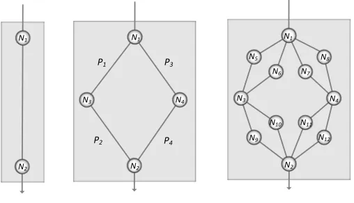
Figure 4: Redundancy Pattern Decomposition
Pattern Topology:The topology of the redundancy pattern follows both the sequence
the sourceN1, the destinationN2and two nodesN3andN4placed in the middle of end
nodes. It also includes four paths: P1=Path(source=N1,destination=N3), P2=
Path(source=N3,destination=N2),P3=Path(source=N1,destination=N4),P4=
260
Path(source=N4,destination=N2). The decomposition phase can be analyzed as
follows:P=Path(source=N1,destination=N2) = (Path(source=N1,destination=
N3)∧Path(source=N3,destination=N2))∨(Path(source=N1,destination=N4)∧
Path(source=N4,destination=N2)). The decomposition procedure (Figure 4) can
continue until atomic links are found. 265
Pattern Constraints: The constraint of redundancy availability pattern refers to the
connectivity between nodes, expressing that if the maximum link range isr, the
dis-tanced between these nodes should be r≥d. When constructing a network from a
source nodeN1to a destination hostN2, any nodes that are added to create the network
betweenN1andN2are assumed to be on the same straight line, even they have been
270
created by the multi-choice-join composition pattern.
Pattern S&D Property: The availability guaranteed by this pattern is related to the
sequence and multi-choice path composition. Whenmare the number of parallel paths
P,nare the number of sub-paths of each parallel path andPro(P)is the probabilistic availability of each sub-path, the probabilistic availabilityProof the composition can
be given by the following formula:
Pro=1−
m
∏
i=1(1−
n
∏
j=1Pro(Pij))
Since the topology of redundancy availability pattern consists of two parallel paths
with two sub-paths in sequence ((P1∧P2)∨(P3∧P4)), the availability Pro will be
equal to:Pro=1−(1−Pro(P1)·Pro(P2))(1−Pro(P3)·Pro(P4)). When the required
availability property of the entire path isreqPro, the network availability should sat-275
isfy the following condition: reqPro≤Pro. In case of equal uptime probability of
each sub-path (Pro(P1) =Pro(P2) =Pro(P3) =Pro(P4) =Pro(P)), the required
avail-ability should satisfy the equation: reqPro≤Pro=1−(1−Pro(P)2)2⇒Pro(P)≥ p
1−√1−reqPro. If there is not any atomic path with this availability, the pattern
will be executed by adding two new nodes and four new paths in the middle distance 280
each new path will be:reqPro0=p1−√1−reqPro. It can easily be proven that the reqPro0≤reqProapplies for requested path availability greater than 62%. Finally, the
recursive execution of the pattern will increase network availability and will guarantee
the required path availability. 285
Rule 3: Inference Rule of Redundancy Availability Pattern 1 r u l e ” R e d u n d a n c y A v a i l a b i l i t y I n f e r e n c e R u l e ”
2 when
3 $N1 : Node ( $ i d 1 : i d , $p1 : p o s i t i o n )
4 $N2 : Node ( $ i d 2 : i d , $p2 : p o s i t i o n )
5 $P : P a t h ( $N1== s o u r c e , $N2== d e s t i n a t i o n , $ r : r a n g e , $d : d i s t a n c e , $ r<=$d ,
6 P r o . name==” A v a i l a b i l i t y ”, $ P r o : P r o . v a l u e )
7 $R : R e q u i r e m e n t ( p a t h ==$P , p r o p e r t y . name==” A v a i l a b i l i t y ”,
8 $ r e q P r o : p r o p e r t y . v a l u e , $Pro<$ r e q P r o , s a t i s f i e d ==f a l s e)
9 t h e n
10 Node $N3 = new Node ( $ i d 1 + $ i d 2 ,new P o s i t i o n ( $N1 , $N2 ) ) ; i n s e r t( $N3 ) ;
11 Node $N4 = new Node ( $ i d 1 + $ i d 2 ,new P o s i t i o n ( $N1 , $N2 ) ) ; i n s e r t( $N4 ) ;
12 P a t h $P1 = new P a t h ( $N1 , $N3 , $ r , $ P r o ) ; i n s e r t( $P1 ) ;
13 i n s e r t(new R e q u i r e m e n t ( $P1 ,new P r o p e r t y (” A v a i l a b i l i t y ”,
14 Math . s q r t (1−Math . s q r t (1−$ r e q P r o ) ) ) ,f a l s e) ) ;
15 P a t h $P2 = new P a t h ( $N3 , $N2 , $ r , $ P r o ) ; i n s e r t( $P3 ) ;
16 i n s e r t(new R e q u i r e m e n t ( $P2 ,new P r o p e r t y (” A v a i l a b i l i t y ”,
17 Math . s q r t (1−Math . s q r t (1−$ r e q P r o ) ) ) ,f a l s e) ) ;
18 P a t h $P3 = new P a t h ( $N1 , $N4 , $ r , $ P r o ) ;i n s e r t( $P2 ) ;
19 i n s e r t(new R e q u i r e m e n t ( $P2 ,new P r o p e r t y (” A v a i l a b i l i t y ”,
20 Math . s q r t (1−Math . s q r t (1−$ r e q P r o ) ) ) ,f a l s e) ) ;
21 P a t h $P4 = new P a t h ( $N4 , $N2 , $ r , $ P r o ) ; i n s e r t( $P4 ) ;
22 i n s e r t(new R e q u i r e m e n t ( $P4 ,new P r o p e r t y (” A v a i l a b i l i t y ”,
23 Math . s q r t (1−Math . s q r t (1−$ r e q P r o ) ) ) ,f a l s e) ) ;
24 modify( $R ){s a t i s f i e d =t r u e};
25 end
Pattern Inference Rule:The pattern rule encodes the described redundancy topology
(Rule 3). In the LHS of this pattern, the rule matches two nodes$N1and$N2(lines
3-4). The pattern also matches a path$P with source the $N1 and destination the
$N2(lines 5-6). The constraint of the pattern topology defines that the link range$r
between the nodes should be less or equal to the distance between$N1and$N2. The 290
S&D property$reqProthat the pattern should guarantee is specified inlines 7-8. When
RHS of the rule. In the RHS, two nodes$N3and$N4should be inserted in parallel
between the$N1and$N2(lines 10-11). Moreover, four new paths and requirements
will be inserted in the knowledge base (line 12-23). Finally, the rule will modify the 295
requirement satisfaction to true. The recursive procedure will be completed when the
distance constraint and required availability property are satisfied.
Rule 4: Verification Rule of Redundancy Availability Pattern 1 r u l e ” V e r i f i c a t i o n o f R e d u n d a n c y A v a i l a b i l i t y R u l e ”
2 when
3 $P : P a t h ( $N1 : s o u r c e , $N2 : d e s t i n a t i o n , $ P r o : p r o p e r t y . v a l u e )
4 $R : R e q u i r e m e n t ( $P== p a t h , p r o p e r t y . name==” A v a i l a b i l i t y ”,
5 $ r e q P r o : p r o p e r t y . v a l u e , $Pro>= $ r e q P r o , s a t i s f i e d ==f a l s e)
6 t h e n
7 modify( $R ){s a t i s f i e d =t r u e};
8 end
Pattern Verification Rule:Rule 4 expresses the verification process, which according
to the redundancy availability pattern can be followed to check a network’s availability.
The rule is able to discover suitable paths (line 3) with verified availability properties 300
(line 4-5) by the use of a predefined set of paths applied in a depth first manner.
5. Implementation and Tool Support
Design patterns can be used for the design of the SDN infrastructure layer or the
verification of existing SDN infrastructures. To give a proof of concept of our approach
and evaluate its applicability for the design and verification of SDN networks we have 305
developed a prototype implementing our framework. In the next subsections, the
anal-ysis of each implementation phase of the S&D Pattern Framework will be presented.
5.1. Architectural Framework
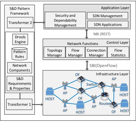
The architectural framework used in our approach includes the developed S&D
Pattern Frameworkwhich applies in an SDN architecture, as shown in Figure 5. The 310
SDN network architecture consists of three high level layers: the infrastructure layer,
data forwarding functionality of the network between end hosts through programmable
switches. The control layer is focused on the control functionality of the network
containing base network service functions such as topology/flow/connection manager 315
and flow statistics. The control layer is connected with the infrastructure layer through
the so-calledSouthbound Interface (SBI). Finally, the application layer includes SDN
applications, SDN/network management and security/dependability management. It is
also able to interact with the control layer through theNorthbound Interface (NBI).
[image:17.612.194.417.255.456.2]S&D Pattern Framework Infrastructure Layer Control Layer Application Layer Network Functions Topology Manager Flow Manager AP OF HOST OF OF HOST HOST Router HOST AP AP AP SDN Applications Switch Connection Manager NBI (REST) SBI(OpenFlow) SDN Management Flow Statistics Transformer 2 Transformer 1 Security and Dependability Management Drools Engine Pattern Rules Network Components S&D Requirements & Properties
Figure 5: Framework Architectural Diagram
The S&D Pattern Framework contains Drools Engineand suitable Java classes. 320
The rules defining S&D patterns were deployed in Eclipse Modelling Tool (4.5) with
the JBoss Drools 6.3. Different Java classes were developed to represent the
differ-entNetwork Componentsof the topology (nodes, links, paths and flows) and theS&D
Requirements and Propertiesas needed byPattern Rules. The framework can interact
with SDN architecture using suitable transformers. Thetransformer 1can export net-325
work topologies, as generated by Drools, into a custom format acceptable by Mininet1,
an emulator which is able to create realistic virtual SDN networks. The created
tom configuration file may contain nodes (i.e., hosts and switches) and links of the
network. Especially with the use of simulators such as Mininet-WiFi [29] and NS32, it is possible to include not only switches and hosts, but also OpenFlow-enabled access 330
points. Thetransformer 2is able to import existing network topologies and flows from
the inventory list of thecontrollersuch as OpenDaylight3. It is also capable to export produced OpenFlow rules as generated by the Drools rules. These topologies and flows
are imported/exported in a REST/XML format by the use of the NBI interface. Finally,
both transformers have been developed in Java as part of our framework. 335
Interaction with Inventory
Topology
S&D Pattern Framework
Convert Facts- Network Topologies Pattern
Rules
Pattern Matching Insert/
Update/ Retract Facts
Insert S&D Patterns
Working Memory (Facts)
Controller Create Physical
Custom Topologies
[image:18.612.154.448.256.389.2]Import Network Topologies to an SDN Emulator
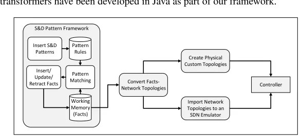
Figure 6: Process Diagram of S&D Pattern Framework for SDN Design
5.2. Design and Verify SDN using the Framework
The framework that we have developed can be used to design an SDN infrastructure
that satisfies particular S&D properties as shown in the process diagram in Figure 6.
More specifically, a network designer canInsert S&D Patternsin our tool asPattern
Rulesand descriptions of network and S&D network requirements and constraints as 340
Factsin theWorking Memoryof the framework. The tool then uses Drools to apply
Pattern Matchingand identify if a network can be formed out of the available types of
nodes that satisfies the required S&D property. The framework is able toConvert Facts
to Network Topologieswhich can be used either toCreate Physical Custom Topologies
or toImport Network Topologiesto an SDN emulator. Finally, the created network will 345
be inserted in the inventory list of theController.
Convert Facts -Flows/Nodes S&D Pattern Framework
Pattern Rules
Insert/ Update/ Retract Facts
Insert S&D Patterns
Working Memory (Facts) Pattern Matching
Controller
GET Network Topology/Flows
Topology Manager
Flow Manager PUT Flows
Programmable Switches
[image:19.612.170.443.123.240.2]POST Flows DELETE Flows
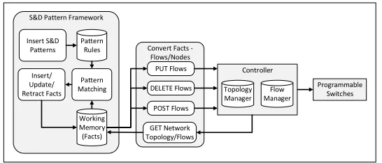
Figure 7: Process Diagram of S&D Pattern Framework for SDN Verification and Adaptation
The verification of an existing SDN network with regards to S&D, is supported
by our S&D pattern framework as shown in Figure 7. In particular, a designer can
Insert S&D Patternsin thePattern Rulesproduction memory of the framework and
S&D requirements theWorking MemoryasFacts. After specifying or importing the 350
network to be verified (GET Network Topologies/Flows), S&D patterns are executed to
realise the verification process and, new paths can be inserted (PUT Flows) or current
paths can be deleted (DELETE Flows) or modified (POST Flows) in theControllerand
consequently in theProgrammable Switches. Through the use of verification patterns,
suitable paths can be found in order to pre-plan and reserve paths with respect to S&D 355
properties. Finally, the proposed framework can be used not only for the verification of
network paths but also at runtime i.e. following a network link failure or when a S&D
property is not guaranteed. The use of our framework at runtime can not only verify a
network but also re-construct it to restore required S&D properties in cases where such
properties have been violated. 360
6. Evaluation and Experiments
The implementation described in Section 5 has been used for an evaluation of our
approach in two different SDN design scenarios. These scenarios and the outcomes of
6.1. Scenario 1 - Design of SDN Networks 365
The first scenario involves the transmission between two host nodes (source and
destination) using wireless-enabled network nodes. Apart from the source and the
des-tination, all the other nodes act as relays that send the received data continuously. To
design an S&D network able to avoid attacks on the communication medium such
as eavesdropping and DoS, the confidentiality and availability patterns that were dis-370
cussed in Section 4 are applied. The inputs to the pattern based network design tool for
both S&D patterns are: (a) the distances between source and destination node of the
network are 500m, 1.000m, 2.000m, 5.000m, 7.000m and 10.000m and (b) the
maxi-mum range of communication link is 100m. The outputs that the tool generates are: (i)
the network nodes, (ii) their position (i.e., the tier in which the nodes should be placed) 375
and (iii) the number of links.
Link-to-Link Confidentiality Pattern: The pattern requires that the exchanged data on
the communication channel should be encrypted. Therefore, each node should be able
to encrypt/decrypt data by applying link-to-link encryption.
Redundancy Availability Pattern: The pattern implies that the path availability is re-380
lated to the probability of an attack. In our experiments we considered 99% the uptime
probability and the required network availability is 99.999% (or less than one-minute
[image:20.612.184.425.494.612.2]daily network downtime) network.
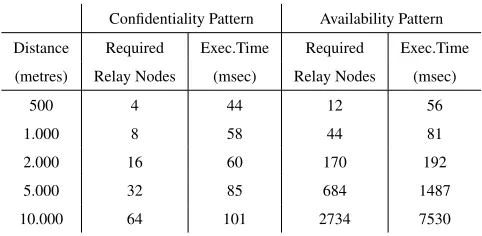
Table 1: Results of Conducted Experiments
Confidentiality Pattern Availability Pattern
Distance Required Exec.Time Required Exec.Time
(metres) Relay Nodes (msec) Relay Nodes (msec)
500 4 44 12 56
1.000 8 58 44 81
2.000 16 60 170 192
5.000 32 85 684 1487
10.000 64 101 2734 7530
The results of the tool, after applying the above two patterns, are presented in Table
1. The table shows the number of nodes of each pattern and the time that was needed 385
confidential-ity pattern, represents also the minimum number of nodes for a functional network,
although the purpose of this pattern is to enable link-to-link encryption. On the other
hand, the requirement of 99.999% availability suggests that a great number of nodes
should be installed, especially for long distance links. 390
The developed S&D network topologies can be transformed to an SDN network by
the use of Mininet emulator, as discussed in Section 5. The created SDN infrastructure
can include hosts and OpenFlow-enabled (wired or wireless) switches as obtained by
the S&D patterns. Then, the emulator is able to forward the topology to a remote
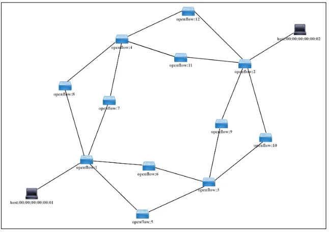
controller such as OpenDaylight. Figure 8 depicts the outputs (nodes and links) of the 395
redundancy pattern when the distance between the source and the destination is 500m,
[image:21.612.145.468.325.553.2]the range is 100m and the uptime probability is 99%.
Figure 8: OpenDaylight SDN Infrastructure Topology
The scenario could be extended by adding multiple end-host. However, the
net-works that would be generated between the same source node and multiple end-hosts
will be disjoint. This is due to the fact that the current set of patternsplacenodes on a 400
straight line between a source and a destination (this point has been clarified in Section
should be added).
6.2. Scenario 2 - Verification and Runtime Adaptation of SDN Networks
The second scenario includes the verification of an existing SDN infrastructure 405
(such as the network topology shown in Figure 8). The initial network topology (nodes
and links) can be obtained from the topology manager of OpenDaylight controller as
discussed in Section 5. However, in this scenario, network nodes and links have
differ-ent channel availability and encryption level as presdiffer-ented in Table 2.
Table 2: S&D Properties of Network Topology
Links l(1
n1 , n5 ) l2 ( n1 , n6 ) l3 ( n1 , n7 ) l4 ( n1 , n8 ) l5 ( n5 , n3 ) l6 ( n6 , n3 ) l7 ( n7 , n4 ) l8 ( n8 , n4 ) l9 ( n3 , n9 ) l10 ( n3 , n10 ) l11 ( n4 , n11 ) l12 ( n4 , n12 ) l13 ( n9 , n2 ) l14 ( n10 , n2 ) l15 ( n11 , n2 ) l16 ( n12 , n2 )
Encrypted X X X X X X X X X X X X X X X X
Availability (%) 99 99 97 99 98 99 99 98 99 97 98 99 98 99 97 99
S&D verification patterns can be executed to define paths and convert them to 410
OpenFlow rules with high priority. As an evaluation test of our approach, the
fol-lowing requirements were inserted in the working memory:
R1= Requirement(path.source ==$n1, path.destination == $n2, property.name ==
”Availability”, property.value == 0.95, satisfied == false)and
R2 = Requirement(path.source ==$n1, path.destination ==$n2), property,name == 415
”Encryption”, property.value == true, satisfied == false).
After the execution of confidentiality and availability verification patterns, a
num-ber of possible solutions were produced. The paths that guarantee both properties are
presented in the following expression in which the∧represents the sequence
compo-sition and∨represent the parallel composition:
SR1∧SR2=l4∧l8∧((l11∧(l15)∨(l12∧l16))
Verification patterns can also be executed to support runtime SDN adaptation in
cases like DoS attacks. In a network fall for example, new alternative network paths
[image:22.612.126.473.293.364.2]be both the detection to identify an attack or failure and the reaction time to transfer 420
the new flow rules to the controller and the switches. This can be done by the use
of node connector statistics as fetched from the OpenFlow-enabled switches to the
OpenDaylight controller. The statistics include receive and transmit packets, errors,
drops CRC errors and collisions. S&D patterns can retrieve these statistics and react
immediately as an intrusion detection mechanism in case of malicious adversaries that 425
create DoS attacks and forward traffic to different secure paths.
7. Conclusion and Future Work
In this paper, we proposed an S&D patterns based framework for the design and
verification of networks that need to satisfy given security and dependability
proper-ties. This is crucial for the design of highly interconnected ICT and CPS that need to 430
preserve S&D properties as the network is the backbone for ensuring such properties.
Our approach is based on S&D patterns which express what conditions and properties
that need to be satisfied by abstract networks of different topologies in order to preserve
particular end-to-end S&D properties. It also includes processes for applying the S&D
patterns for this purpose. Our approach is aimed at minimizing the effects of passive 435
and active attacks on physical layer. To prove the applicability of our S&D patterns
ap-proach, we developed a prototype tool supporting the design and verification of SDN
network infrastructures and evaluated in initial experiments involving design and
ve-rification scenarios involving the security properties of confidentiality and availability.
Our future plans involve the development of the patterns specification scheme and pat-440
tern instances suitable to guarantee properties not only at the infrastructure layer, but
also at the control and application layer. We are also planning to extend our framework
with more S&D patterns and new functional capabilities to cover not only horizontally
layered designs but also vertical layers of SDN architectures.
References
445
[1] P. Agyapong, M. Iwamura, D. Staehle, W. Kiess, A. Benjebbour, Design
[2] N. E. Petroulakis, G. Spanoudakis, I. G. Askoxylakis, A. Miaoudakis, A.
Tra-ganitis, A pattern-based approach for designing reliable cyber-physical systems,
in: Globecom 2015, IEEE, 2015. 450
[3] D. C. Schmidt, Model-driven engineering, in: Computer Society, Vol. 39, 2006,
pp. 286–298.
[4] K. Doddapaneni, E. Ever, O. Gemikonakli, I. Malavolta, L. Mostarda, H.
Muc-cini, A model-driven engineering framework for architecting and analysing
wire-less sensor networks, in: SESENA, 2012. 455
[5] C. Preschern, N. Kajtazovic, C. Kreiner, Applying patterns to model-driven
de-velopment of automation systems: an industrial case study, in: Proceedings of the
17th European Conference on Pattern Languages of Programs, ACM, 2012, p. 5.
[6] B. Hamid, C. Percebois, D. Gouteux, A methodology for integration of patterns
with validation purpose, in: Proceedings of the 17th European Conference on 460
Pattern Languages of Programs, ACM, 2012, p. 8.
[7] E. Gamma, R. Helm, R. Johnson, J. Vlissides, Design patterns: elements of
reusable object-oriented software, Pearson Education, 1994.
[8] G. Spanoudakis, S. Kokolakis, Security and Dependability for Ambient
Intelli-gence, Springer Science & Business Media, 2009. 465
[9] H. Mouratidis, Software Engineering for Secure Systems: Industrial and
Re-search Perspectives: Industrial and ReRe-search Perspectives, IGI Global, 2010.
[10] M. Schumacher, E. Fernandez-Buglioni, D. Hybertson, F. Buschmann, P.
Som-merlad, Security Patterns: Integrating security and systems engineering, John
Wiley & Sons, 2013. 470
[11] E. Fernandez-Buglioni, Security patterns in practice: designing secure
[12] B. Hamid, J. Geisel, A. Ziani, J.-M. Bruel, J. Perez, Model-driven engineering for
trusted embedded systems based on security and dependability patterns, in: SDL
2013: Model-Driven Dependability Engineering, Springer, 2013, pp. 72–90. 475
[13] H. Petritsch, Service-oriented architecture (soa) vs. component-based
architec-ture, 2006.
[14] G. G¨ossler, J. Sifakis, Composition for component-based modeling, 2005.
[15] L. Pino, K. Mahbub, G. Spanoudakis, Designing Secure Service Workflows in
BPEL, in: ICSOC 2014, Paris, France, 2014. 480
[16] L. Pino, G. Spanoudakis, A. Fuchs, S. G¨urgens, Discovering secure service
com-positions, in: 4th International Conference on Cloud Computing and Services
Sciences, Barcelona, Spain, 2014.
[17] M. C. Jaeger, G. Rojec-goldmann, M. Gero, QoS Aggregation for Web Service
Composition using Workflow Patterns, no. Edoc, 2004. 485
[18] E. Liotou, G. Tseliou, K. Samdanis, D. Tsolkas, F. Adelantado, C. Verikoukis,
An sdn qoe-service for dynamically enhancing the performance of ott
applica-tions, in: Quality of Multimedia Experience (QoMEX), 2015 Seventh
Interna-tional Workshop on, IEEE, 2015, pp. 1–2.
[19] R. Vilalta, A. Mayoral, D. Pubill, R. Casellas, R. Mart´ınez, J. Serra, C. Verik-490
oukis, R. Mu˜noz, End-to-end sdn orchestration of iot services using an
sdn/nfv-enabled edge node, in: Optical Fiber Communication Conference, Optical
Soci-ety of America, 2016, pp. W2A–42.
[20] I. F. Akyildiz, A. Lee, P. Wang, M. Luo, W. Chou, A roadmap for traffic
engi-neering in sdn-openflow networks, Vol. 71, Elsevier, 2014, pp. 1–30. 495
[21] J. Reich, C. Monsanto, N. Foster, J. Rexford, D. Walker, Modular sdn
[22] W. Zhou, L. Li, M. Luo, W. Chou, Rest api design patterns for sdn northbound api,
in: Advanced Information Networking and Applications Workshops (WAINA),
2014 28th International Conference on, IEEE, 2014, pp. 358–365. 500
[23] J. Halpern, C. Pignataro, Service function chaining (sfc) architecture, Tech. rep.
(2015).
[24] R. Cohen, K. Barabash, B. Rochwerger, L. Schour, D. Crisan, R. Birke,
C. Minkenberg, M. Gusat, R. Recio, V. Jain, An intent-based approach for
network virtualization, in: Integrated Network Management (IM 2013), 2013 505
IFIP/IEEE International Symposium on, IEEE, 2013, pp. 42–50.
[25] W. Van Der Aalst, A. Ter Hofstede, B. Kiepuszewski, A. Barros, Workflow
pat-terns, Vol. 14, Springer, 2003.
[26] Drools, Business rules gement system solution,www.drools.org.
[27] C. Forgy, Rete: A fast algorithm for the many pattern/many object pattern match 510
problem, Vol. 19, Elsevier, 1982, pp. 17–37.
[28] A. Geraci, F. Katki, L. McMonegal, B. Meyer, J. Lane, P. Wilson, J. Radatz,
M. Yee, H. Porteous, F. Springsteel, IEEE standard computer dictionary:
Compi-lation of IEEE standard computer glossaries, 1991.
[29] R. R. Fontes, S. Afzal, S. H. Brito, M. A. Santos, C. E. Rothenberg, Mininet-wifi: 515
Emulating software-defined wireless networks, in: 11th International Conference