Abstract: This paper presents a qualitative analysis of 3D routing algorithm in 8x8x4 mesh network topology. The traffic distribution in 3D routing algorithm has limited bandwidth along vertical links. Different traffic patterns were used during simulation. The simulation is performed on different traffic pattern. The proposed 3D algorithm has been used to perform better in terms of latency and throughput in comparison with existing routing algorithm. The simulation is done with synthetic traffic pattern in a 8×8×4 3D mesh system design which shows that with existing routing algorithm the network is powerful and steady under various traffic patterns, A weighted adaptive routing algorithm for 8×8×4 3D mesh NoC frameworks with arbitrary traffic pattern reveals to accomplish critical execution improvement in terms of Maximum delay and throughput with existing XYZ routing algorithm. Throughput for WARA at packet injection ratio 0.26 is 0.0009893 and maximum delay at packet injection ratio 0.26 is 976.
Index Terms: 3D NoC Mesh; Adaptive routing; Vertical interconnect; CMOS technology; Packaging density
I. INTRODUCTION
The multi-center design has turned out to be very significant arrangement in order to talk about the exhibition of the regularly developing arrangement of information transmission. Be that as it may, so as to misuse the advantages of such design, it is very significant to keep up the information moving between the centers of the proficient system. The Network-on-Chip (NoC), which handles the tracery based scaling issue and the related interconnect issue [1], which gives an approach to actualize the effective on-chip information contact engineering. In spite of every one of these endeavors, as the intricacy of framework expands, the two-dimensional (2D) plane is never again effective agonizing because of long inertness [2] [3]. A standout amongst the foremost productive answers to conquer this issue of the robbery and maintain the pace of development in framework scaling to merely build the parts of the system as an example utilize 3 dimensional (3D) incorporation, within which varied layers of gadgets are stacked along. Decrease of wire length and effort more and more chemical element zone empowers acknowledging exceptionally ramified framework combination. Consequently 3D NoC is turning into a significant idea for ramified on-chip framework precious stone giving biggest versatility, higher throughput, and lower control utilization as appeared in the underneath figure 01 [4] – [8].
Revised Manuscript Received on June 15, 2019.
Nidhi Syal, Electronics and Communication Engineering, Chandigarh Engineering College, Landran, Mohali, Punjab, India.
Preeti Bansal, Electronics and Communication Engineering, Chandigarh Engineering College, Landran, Mohali, Punjab, India.
In this 3D based framework mix innovation, the various layers are stacked together utilizing vertical connections which is a standout amongst the most well known and up and coming procedure dependent on the vertical connecting approach for example Through Silicon Via (TSV) [9] [10], which slices crosswise over diminished silicon substrates to set up between pass on network. This method of TSV has turned out to be very well known being used in light of the fact that’s it permits fine pitch, high thickness, and great similarity with standard
[image:1.595.322.553.329.497.2]CMOS creation process. However, as per data every method has related constraints, in this way, this procedure TSVs likewise has its own related issues which are very testing one
Fig. 1: Schematic arrangement of 3D NoC [8]
These restrictions can be effectively comprehended from the above figure 01 for example the TSV landing cushions required in the middle of each multi layers are short long which is in charge of a steady holding. In view of this idea, as the quantity of system hubs increments in each layer, the quantity of TSVs likewise increments, accordingly prompting high zone utilization. For instance, if there should arise an occurrence of NoC arrange, the 8x8x8 hubs existing in each layer of the system with every hub having 64-bit vertical TSV wires that is dependable to associate the supporting hubs in the encompassing layers of the system with the cushion measurement of 10μm. In view of the leaving writing on this issue, if there should arise an occurrence of low thickness arrange the parameters of the TSV apparatus are a pitch of 50μm [11] [12], the complete territory visual projection will be more than 10mm. Therefore, if there should be an occurrence of a system with high thickness, requires a pitch estimation of 16 µm [11] [12], the TSVs based system will expend a territory of roughly 2.1 mm2 of zone, which can't be disregarded and turns into a very testing issue when the system size increments.
3D NoC Network using Adaptive Algorithm
for 8x8x4 Mesh
The second best restriction of the TSV system offer ascent to the steering blockage because of the expansion in the system appropriation [13], which ends up being down to earth issue for the fast IC structure and creation utilizing the CMOS innovation. At long last, there are not many specialized issues which exist at the mechanical dimension that can be streamlined for the better execution of the NoC based systems, this TSV apparatus ends up providing very low yield in contrast with the overall innovation. Subsequently, with every one of these negative marks, vertical connections will in general have various qualities including the restricted transmission capacity when compared to horizontal
links. This can be true not just
for TSVs however conjointly for different vertical
interconnect technologies like inductive coupling [14] [15].
The literature shows that these limitations cane be minimized simply by employing the concept of soap scheme with advanced clock domain in the vertical transmission [16] and the use of bus hybrid configuration [3][17]. But this solution in turn require the use of asynchronous design based implementation with high design convolution, making them quite strong to be embraced for the practical applications. Hence, in view of this thorough writing review, the writer has advanced that all these above examined issues can be effectively dispensed with or upgraded upto the acknowledgment level basic by utilizing the most suitable system directing calculation as opposed to suspecting to overhaul the equipment modules. In this paper, weighted adaptive routing algorithm (WARA) is purposed for calculation of 3D NoC in order to get better throughput of 3D network system where vertical data transmission is restricted. By making an allowance for neighbor hubs' blockage data, provide various loads to vertical guidance and even bearing for traffic figuring, just as enchanting separation from current hub to bundles' goal into thought, we viably recover the correspondence idleness and throughput of a 3D work system.
II. LITERATURESURVEY
A.Vertical Interconnect:
From the above dialog, it has been discovered that the TSV calculation has certain confinement related with it for a given 3D work for example the territory utilization and moderately low yield which are profoundly testing in nature for the vertical connections based systems. The writing concentrate gives some valuable data which mirrors that there are sure usage completed by the scientists [16] utilizing the methodology of the vertical interconnect serialization in order to address such issues that gives over 70% of the impression territory in a system yet with a decrease in throughput for a non-uniform system. This arrangement additionally utilizes the diverse timing plan connected to the information transmission in both level just as vertical headings in the event of synchronous frameworks. So also, if there should arise an occurrence of another exchange [12], the pressing device has been utilized to handle the issue of TSV in which four system hubs share a solitary TSV pack which thus evacuate the issue related with the offbeat plan issue with a suppositions that the neighboring switches once in a while transmit information by means of their vertical channels in the meantime with the issue of additional design intricacy and lower attainability.
B.3D Routing:
So as to comprehend the idea of 3D versatile directing, we have to experience the social execution of the systems utilizing the 2D steering calculations that has unavoidable impediments, for example, clog issue with unaware directing calculations [18], West-First [19], and irregular [19] achieve directing without taking into consideration the traffic state of the system. What's more, there are some more blockage mindful calculations that has been put sent by different analysts, for example, DyXY [20], NOP [21], DBAR [22], and CATRA [23], the course choice is performed utilizing the clog status of the system. Be that as it may, there have not been numerous investigations on 3D NoC directing when contrasted with 2D NoC steering with an issue of constrained vertical transfer speed of 3D stacked work engineering. Another analyst Chao et al. [24], have advanced a substitute methodology for the warm mindful versatile directing utilizing a proactive descending steering in order to guarantee the warm wellbeing for throttled 3D NoC with an impediment of symmetric 3D NoC. Another gathering of scientists have advanced an answer with the utilization of hybridization structure for example Rahmani et al. [3] with the utilization of a transport and structure a hybridization plan to alleviate vertical bottleneck. Likewise presented a clog mindful between layer steering calculation called Adaptive Z for 3D stacked work NoC models which picks a vertical channel according to traffic condition and does XY coordinating when package in the goal layer. As an extension to this work [17], Rahmani et al. have in like manner inspected about an adaptable checking stage for stack Mesh 3D NoC plans, named ARBNET in order to lead traffic observing, warm administration, and adaptation to non-critical failure.
C.Traffic disseminating plan
So as to comprehend the working of the appropriated traffic heap of the system utilizing the more compelling restricted vertical connections, it is required to assemble all the related data and afterward actualize the calculation to acquire the ideal parameters of the 3D work. For this equivalent, one can utilize the different accessible measurements that characterizes the presentation of the traffic state of a system. The most widely recognized instances of these measurements of the system are the staying cushion space, accessible virtual channels, crossbar request, or blend of these variables. As talked about over, the data transmission of vertical connections in a 3D work system is moderately low when contrasted with that of even connections, however neither traditional measurement directing calculations, as XYZ, nor other offered calculations focusing at 3D NoC steering take exceedingly plausible blockages in vertical connections into thought. In view of these dialogs, one can choose the non-insignificant way based versatile steering plan to disperse interchange load over the system particularly in the vertical course. Be that as it may, since non-insignificant way steering permits misrouting for example a steering of a bundle toward a path which isn't on the negligible way to its goal, it might result in superfluously long directing ways, along these lines expanding the inactivity just as diminishing the throughput.
dormancy and boost the throughput while conceding misrouting. We have a tendency to don't have the knowledge of worldwide system traffic load and therefore the correct result of traffic load dispersion on the system inactivity and turnout, we have a tendency to simply plan to applicable the traffic load domestically whereas puzzling over the heading toward the goal. In this manner, so as to limit the traffic blockage particularly, in the vertical course with a condition to stay away from superfluous long steering ways due to misrouting, it requires the heuristically doled out various loads toward every path for need figuring dependent on traffic. Presently so as to relegate the loads to the said calculation, there exist three unique circumstances in a considered system for example vertical course, level bearing and flat heading which isn't on an insignificant way (i.e., misrouting). Presently during the execution of this directing calculation to the thought about work of the segments, it mirrors that the ideal execution can't e accomplished just by applying the non-negligible steering way, particularly if there should arise an occurrence of the presence of certain hotspots in the system [25]. Specifically, when a problem area is close to the goal, it will be exceedingly conceivable that bundles pick non-negligible course and meander around the goal hub, which will spread blockage over a range close to the goal and square different parcels that need to experience it.
Presently given us a chance to expand the operational ideas of this steering calculation utilized for example nom-insignificant way which utilizes distinctive facilitate for every predominant parameters of the system for example current hub and goal hub as Xdiff, Ydiff and Zdiff. The loads of the vertical close just as the horizontal close are doled out individually to vertical bearing and flat heading when the present hub is near the goal. In this talk, genuine once the objective is inside one hop in all aspects of the measurement i.e., at the most 3 skips out and out to the objective from the present center is treated as "close". The majority of vertical way and even far min are apportioned separately to vertical heading and level seminar on an irrelevant way once the present center also could be an extraordinary separation from the objective. In addition, the greatness of even far bypass is consigned to level concerning a non-irrelevant methodology for misrouting of the group. Be that because it might, paying very little relevance "far" or "close", we tend to don't allow misrouting vertical approach, since it'd lead to a serious overhead as a result of the strained
Knowledge transfer capability of vertical transmission. During the reproduction procedure, it has been discovered that exhibition of 3D work system is exceptionally subject to weight esteems for the "a long way from goal" case that gives the most ideal presentation in the information transmission inside the system. In light of throughput of this examination, the correlation between various blends of loads has been gotten with a lot of weight esteems that gives the best execution.
D.Halt Avoidance
By and large, the versatile directing technique requires a strategically plan of the steering calculation to maintain a strategic distance from the issue of the stop which happens in an interconnect range at whatever point there is a cyclic reliance for assets, for example, supports and channels. One can likewise utilize the virtual channels just as measurement inversion (DR) number plan accessible in the current written
works [26] in order to maintain a strategic distance from cyclic reliance. In this manner every parcel will relegate a DR number (DR#), that is the check of the occasions a bundle has been steered from a senior measurement to a junior measurement. DR#s are resolved as pursues:
1) DR#s of all parcels is instated to 0;
2) Each time a parcel is steered commencing divert in measurement Di to a direct in measurement Dj, on the off chance that I > j, the DR# is increased.
In view of the above discourse, we may think about the vertical heading first; hen the measurement request is Z, Y, and X. Every single virtual channel are likewise partitioned keen on classes 0 to r (i.e., there are r+1 virtual directs in each port), where r chairs furthest cutoff on the quantity of measurement inversions allowed. Bundles with DR# < r might be steered to any course yet should utilize a virtual channel of class DR# (really, directing of parcels with DR#=r-1 requires exceptional consideration in a three-or advanced-dimensional system, yet we exclude the subtleties in this paper because of space restriction). When a parcel makes its last measurement inversion, which means DR# =r, it have to begin doing measurement request directing through virtual channel r.
E.Traffic Condition Calculation
In this paper, the traffic toward every path of the information transmission gets measured by the staying support space accessible in the relating neighbor hub of the system which gets transmitted inside them by utilizing additional associations I encompassing hubs. Seeing as each virtual direct in our framework has cushion limit of four bounces, the breadth of this extra association is 2 bits. In arouse of getting the free support space data, we decide the traffic condition for the comparing track. Here, we utilize a direct capacity given by
Traffic condition = free cushion space × allotted weight (1)
F. By and large Algorithm Description
The heading for steering of a parcel at a hub is chosen passionate about the estimation of traffic condition as an example the bearing with the best Traffic condition with estimations of most astounding would like. In the calculation, the bearing where the information parcel needs to navigate relies upon the arrange distinction between current hub and goal hub, DR# of the bundle, just as the traffic condition determined for all applicant headings. All in all instances of the thought about system, the said calculation of steering considers four headings barring the one from which the parcel has arrived. The capacity with the best outcomes is required to be picked toward the path with the most elevated esteem that speaks to the least blocked bearing of the information stream in the predefined pivot of the system
III. 3DNOCEVALUATIONMODEL
The examination of 3D steering calculation in 8×8×4 work arrange on chip topology is completed on Noxim Simulator. The subjective investigation included the parameter including Total Packet Received (TPR), Total got flits(TRF), Global
normal delay(cycles)
(GAD), Global normal
throughput
Throughput (flutters/cycle/IP)(T), Max delay (cycles)(MD), Total vitality (J)(TE), average control (J/cycle)(AP), average control per switch (J/cycle)(APPR), average holding up time
in each cushion (cycles)(AWT) as appeared Table I for XYZ
[image:4.595.32.583.120.269.2]Routing algorithm and Table II for
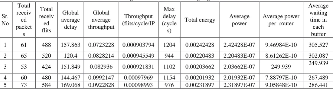
Table I: Average values of WARA Routing Algorithm
Sr. No Total receiv ed packet s Total receiv ed flits Global average delay Global average throughput Throughput (flits/cycle/IP Max delay (cycle s)
Total energy Average
power
Average power per router
Average waiting
time in each buffer
1 61 488 157.863 0.0723228 0.000903794 1204 0.00242428 2.42428E-07 9.46984E-10 305.527
2 65 520 120.4 0.0828214 0.000945549 944 0.00220483 2.20483E-07 8.61262E-10 302.087
3 53 424 151.849 0.082936 0.000921831 1102 0.00203662 2.03662E-07 249.939 249.939
4 60 480 144.467 0.0992147 0.00097969 1154 0.00201932 2.01932E-07 7.88797E-10 267.489
5 73 584 169.068 0.0922828 0.00098993 976 0.00231897 2.31897E-07 9.05848E-10 286.441
WARAP Routing Algorithm. The minimum packet received at packet injection ratio 0.18 was 53, The Global average delay observed was 151.849, Throughput 0.000921831, Max Delay was 1102, the total energy was 0.00203662 and the waiting time in each buffer was 249.939. The maximum
[image:4.595.33.577.359.485.2]packets received at packet injection ratio 0.26 were 73, The Global average delay observed was 169.068, throughput 0.00098993, maximum delay was 976 the total observed energy was 0.00231897 and average waiting time in each buffer was 286.441
Table II: Average values of XYZ Routing Algorithm
Sr. No Total received packets Total receiv ed flits Global average delay Global average throughp ut Throughput (flits/cycle/I P Max delay (cycles)
Total energy Average power Average power per router Average waiting time in each buffer
1 73 584 163.027 0.078229 0.000912591 2938 0.00236091 2.36091E-07 9.22231E-10 262.24
2 69 552 191.71 0.064843 0.000862586 2101 0.00227522 2.27522E-07 8.8876E-10 343.363
3 68 544 166.5 0.064291 0.000877507 2002 0.00217478 2.17478E-07 8.49522E-10 279.365
4 65 520 140.985 0.094675 0.000881444 1942 0.00205728 2.05728E-07 8.03626E-10 281.597
5 50 400 143.3 0.081092 0.000869652 1386 0.00202226 2.02226E-07 7.89946E-10 251.011
The minimum packet received were 50 at packet injection ratio 0.18, the global average delay observed was143.3, the observed throughput was 0.000869652, the observed maximum delay was 1386, the total energy was 0.00202226 and average waiting time in each buffer was 251.011.
The maximum packet received were73 at packet injection ratio 0.26, the global average delay observed was 168.027. The observed maximum delay was 2938, the total energy was
0.00236891, the observed throughput was 0.000912591 and average waiting time in each buffer was observed to be 262.24
The traffic pattern used were poison in both the cases i.e. in XYZ and WARA routing (weight adaptive routing algorithm) .The WARA was observed to outperform then XYZ routing over the varied range of packet injection ratio from 0.18 to 0.26 with maximum throughput 0.00098993 as compared to XYZ throughput.
IV.ALGORITHMFORWEIGHTEDADAPTIVEROUTING
INPUT X, Y, Z
CALCULATED WEIGHT As Xw=XC–X D
IF -1≤Xw≤1
IF -1≤Yw≤1
If Zw<0 If
-1≤Zw≤1
If Zw>0
DPW = V close UPW = V close
DPW = V close UPW = V close
If Yw>0
If Zw>0
If Zw <0
DPW = V far UW = V far
If Yw>0
If Yw <0
SPW = h far min NPW = h far detour
WPW = h far min EPW = h far detour
If Xw>0
If Xw <0
EPW = h far min WPW = h far detour
WPW = h far min EPW = h far detour
EPW =h close WPW = h close
If Xw<0 SPW = h close
If Xw>0
NPW = h close
In the flow chart, three inputs (X, Y, Z) have been considered then their weighted difference has been calculated where Xw represents difference of X Coordinates and same for Yw and Zw. Port weights are calculated for different inputs i.e. for Z down port weight (DPW) and upper port weight (UPW) have been calculated as per condition given in flow chart. In the same way for Y South port weight (SPW) and north port weight (NPW) and for X east port weight (EPW) and west port weight (WPW) are considered.
Table III: Description of the terms used in the algorithm
Sr.
No
Terms
Description
1. V close Weight assigned to vertical direction
2. h close Weight assigned to h close
3. V far
Weight assigned to vertical direction on a
minimal path when the current node is far
from dist.
4. h far
min
Weight assign to horizontal direction
on a minimal path when the current node
is far from dist.
5. h far
detour
Weight assign to horizontal direction
on a non- minimal path for misroute the
packet
V.RESULTANDDISCUSSION
A.
Throughput in XYZ and WARAThe routing algorithm WARA (Weighted Adaptive Routing Algorithm) was observed to provide maximum throughput having value 0.00098993 as compared to XYZ routing algorithm whose throughput with minimum value of 0.0008626. The WARA outperformed as compared to XYZ routing algorithms as shown in figure 2.
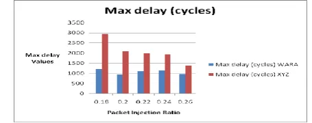
B.Maximum Delay in XYZ and WARA
While minimum delay with respect to high throughput was observed in case of WARA routing having value 976. The maximum delay with respect to throughput was observed with value 1386 in case of XYZ routing algorithm.
VI.CONCLUSION
The proposed Weighted Adaptive routing algorithm (WARA) was seen to get approximately higher throughput under arbitrary traffic design. The proposed calculation shows that throughput is approximately 40% higher than XYZ algorithm at the same point the delay is minimum for WARA. Although simulation is performed for 8×8×4 3D NOC however it isn't constrained to limited parameters and in this way it can be connected to different topologies’.
Fig. 2: Throughput Comparison in XYZ and WARA Routing
Fig. 3: Maximum Throughput Comparisons in XYZ and WARA Routing
ACKNOWLEDGMENT
This work was supported by UTU as per prerequisites against PhD in Computer Sciences.
REFERENCES
[1]. W.J. Dally and B. Towles, “Route packets, not wires: On-chip interconnection networks,” in Proc. DAC, 2001, pp. 684-689. [2] I. Loi, S. Mitra, T.H. Lee, S. Fujita, and L. Benini, “A low-overhead fault tolerance scheme for TSV-based 3D network on chip links,” in Proc. ICCAD, 2008, pp. 598-602.
[3] A.-M. Rahmani et al., “Congestion aware, fault tolerant, and thermally efficient inter-layer communication scheme for hybrid NoC-bus 3D architectures,” in Proc. NOCS, 2011, pp. 65-72.
[4] A. Jantsch and H. Tenhunen, Networks on Chip. Kluwer Academic Publishers, 2003.
[5] B.S. Feero and P.P. Pande, “Networks-on-chip in a three-dimensional environment: a performance evaluation,” IEEE Trans. Comput., vol. 58, no. 1, pp. 32-45, Jan. 2009.
[6] H. Matsutani and M. Koibuchi,“Tightly-coupled multi-layer topologies for 3-D NoCs,” in Proc. ICPP, 2007, pp. 75-75.
[7] C. Seiculescu, S. Murali, L. Benini and G. De Micheli, “Sunfloor 3D : a tool for networks on chip topology synthesis for 3D systems on chips,” in Proc. DATE, 2009, pp. 9-14.
[8] V.F. Pavlidis and E.G. Friedman, “3-D topologies for networks-on- chip,” IEEE Trans. VLSI Syst., vol. 15, no. 10, pp. 1081-1090, Oct. 2007. [9] V.F. Pavilidis and E.G. Friedman, Three-dimensional Integration Circuit Design, Morgan Kaufmann, 2008.
[10] A.-M Rahmani et al., “Power and area opitmization of 3D networks-on-
AUTHORSPROFILE
Nidhi Syal is currently working as an Assistant Professor at Chandigarh Group of Colleges, Landran, Mohali, India. She is pursuing her P.hd from Uttrakhand Technical University Dehradun, She completed her M.Tech .
Preeti Bansal is currently working as an Assistant Professor
![Fig. 1: Schematic arrangement of 3D NoC [8]](https://thumb-us.123doks.com/thumbv2/123dok_us/8192966.258534/1.595.322.553.329.497/fig-schematic-arrangement-d-noc.webp)