University of Southern Queensland
Faculty of Engineering and Surveying
Development and Testing of
a Portable GNSS Network Solution
using the Magellan ProMark3.
A dissertation submitted by
Scott Taylor
in
In fulfillment of the requirements of
Courses ENG4111 and ENG4112 Research Project
Towards the degree of
Bachelor of Spatial Science (Surveying)
ABSTRACT
With increasing development and expansion of Continuously Operating Reference Station (CORS) networks, globally and at home such as Sydnet, Global Navigation Satellite System users have greater options of utilizing reference station networks to receive correction data and undertake Real Time surveys without the need of supplying their own base station. A large majority of GNSS built today are
equipped with built in mobile technology which utilize bidirectional communication including Internet based cellular connections. With increasing coverage of wireless internet, users will be able to utilize this technology in more places than they could ever before.
The ProMark3 RTK GNSS receiver transmits correction data via a conventional 0.5 watt UHF radio. This allows a working range of up to 1.5km in open areas and 0.3 – 0.7km in urban built up areas. Unidirectional communication such as UHF also has its limitations including line of sight requirements, transmitter power, broadcasting antenna height limitations, reliability of the link and
governmental restrictions such as licensing and operational limitations. Alternative options for receiving correction data are made available within the ProMark3’s onboard software, which include Networked Transmit of RTCM via Internet Protocol (NTRIP) and Direct Internet Protocol (DIP). These methods can extend that working range to 10km which is the recommended limit for RTK surveying. Built in wireless technology is not present in the ProMark3 however the user can still
connect using a separate web enabled phone with Bluetooth technology. The advantage with this option is that the phone can be still used whilst you work, giving you even greater flexibility.
This research project will explore the performance of the ProMark3 using Direct IP. Two different portable base reference stations to broadcast corrections will be designed. They include an office based
The use of CORS as an alternative to receiving correction data is improving work turn around time and field efficiencies, improving security as only one GPS is being utilized and offering survey firms the chance to experiment with this technology without a large expense upfront.
The concept of a portable Direct IP station will allow users to operate privately run reference station networks from the office or the field. The benefit of a portable base station is that you can disassemble the base quickly and take it anywhere you decide to work. This will allow the operator and other users the chance to access data in areas not serviced by CORS and create opportunities for surveyors wanting to experiment with this alternate technology. The future may see an increasing amount of private
University of Southern Queensland
Faculty of Engineering and Surveying
ENG4111 & ENG4112 Research Project
Limitations of Use
The council of the University of Southern Queensland, its Faculty of Engineering and Surveying, and
the staff of the University of Southern Queensland, do not accept any responsibility for the truth, accuracy or completeness of the material contained within or associated with this dissertation.
Persons using all or part of this material do so at their own risk, and not at the risk of the Council of the
University of Southern Queensland, its Faculty of Engineering and Surveying or the staff of the University of Southern Queensland.
This dissertation reports an educational exercise and has no purpose or validity beyond this exercise. The sole purpose of the course pair entitled “Research Project” is to contribute to the overall education
within the student’s chosen degree program. This document, the associated hardware, software, drawing, and other material set out in the associated appendices should not be used for any other purpose: if they are used, it is entirely at the risk of the user.
Prof F. Bullen
Dean
CERTIFICATION
I certify that the ideas, designs and experimental work, results, analysis and conclusions set out in this dissertation are entirely my own efforts, except where otherwise indicated and acknowledged.
I further certify that the work is original and has not been previously submitted for assessment in any other course or institution, except where specifically stated.
Scott Taylor
Student Number: 0019922860
________________________
(Signature)
ACKNOWLEDGEMENTS
At the beginning of this project I had never used GPS in my working life as a surveyor. The idea of taking on this project was exciting and challenging. I knew very little about CORS, VRS and Direct IP. With the numerous problems and situations I had to overcome I am very confident with my new ability and have achieved a life long dream of finally understanding the mystery behind GPS.
I would like to thank my supervisors Associate Professor Kevin McDougall and Mr. Peter Gibbings of the University of Southern Queensland for their advice and guidance.
I would like to thank Mr. Ian Iredale of Mapsoft www.mapsoft.com.au. It was Ian’s idea to investigate
the use of Direct IP with the ProMark3. Thank you for your advice, the use of your ProMark3 RTK equipment, the constant emails and late evening correspondence and for your friendship.
I would also like to thank Mr. Peter Butlin and Mr.Viren Kilara of Sagem Australiasia. Sagem are the
Australian distributors for the Magellan ProMark3. They also generously provided me with additional equipment and gave me valuable advice and time to answer questions related to my research.
I would like to thank my employer Mr. Robert “Alf” Martin. Thank you for being patient and understanding throughout this project. As a two man team I realize it was difficult to make room for
testing within our busy work schedule. Thank you for giving up your time on weekdays and weekends to help support me throughout this project.
Finally, I would like to thank my wife, daughter and new born son, born in the weekend before
submission of this project, for their patience and understanding. I sacrificed many family hours and weekends during this year to complete testing and compiling of this dissertation.
TABLE OF CONTENTS
ABSTRACT i
LIMITATIONS OF USE iii
CERTIFICATION iv
ACKNOWLEDGEMENTS v
LIST OF FIGURES ix
LIST OF TABLES xii
NOMENCLATURE AND ACRONYMS xiii
CHAPTER 1 - INTRODUCTION
1.1 RESEARCH STATEMENT 1
1.2 RESEARCH AIMS AND OBJECTIVES 2
1.3 BACKGROUND TO PROBLEM 3
1.4 CONCLUSION 4
CHAPTER 2 - LITERATURE REVIEW
2.1 INTRODUCTION 5
2.2 REAL TIME KINEMATIC (RTK) SURVEYING AND LIMITATIONS 5
2.3 REAL TIME NETWORKS 7
2.4 INTERNET STREAMING OF RTCM VIA INTERNET PROTOCOL 11
2.5 DIFFERENTIAL CORRECTION SERVERS 14
2.6 INTERNET BANDWIDTH 17
2.7 RECEIVING CORRECTION DATA 19
2.8 NTRIP / DIRECT IP – RESEARCH AND TESTING 20
2.9 CONCLUSION 23
CHAPTER 3 - EQUIPMENT CONFIGURATION & DESIGN
3.2 PROJECT BACKGROUND 24 3.3 DESIGN OF A PORTABLE OFFICE / HOME BASED GNSS SOLUTION 27
3.4 DESIGN OF A PORTABLE FIELD BASED GNSS SOLUTION 35
3.5 CONNECTING THE PROMARK3 TO THE INTERNET AND DIRECT IP 41
3.6 CONCLUSION 45
CHAPTER 4 - METHOD
4.1 INTRODUCTION 46
4.2 INITIAL TESTING 46
4.3 THE TEST RANGE 48
4.4 STATIC SURVEY 50
4.5 ABSOLUTE VERSES RELATIVE MEASUREMENT 52
4.6 TEST CONDITIONS AND PROCEDURES 54
4.7 RANGE TESTING IN FLOAT SOLUTION 55
4.8 BATTERY PERFORMANCE AFFECTING THE PROMARK3 55
4.9 INTERNET SPEED 56
4.10 CONCLUSION 56
CHAPTER 5 - ANALYSIS OF RESULTS
5.1 INTRODUCTION 57
5.2 STATIC AND KNOWN POINT – TIME TO FIX 57
5.3 REPEATABILITY OF POSITION 63
5.4 HEIGHT DIFFERENCES OBSERVED AT STATIONS 2 – 9 68
5.5 FLOAT SOLUTION PERFORMANCE OF PROMARK3 69
5.6 LATENCY 70
5.7 BATTERY PERFORMANCE 71
5.8 INTERNET PERFORMANCE 72
5.9 PACKET DATA SIZE 73
CHAPTER 6 - DISCUSSION AND CONCLUSION
6.1 INTRODUCTION 74
6.2 DISCUSSION OF PERFORMANCE 74
6.3 QUALITY CONTROL AND MANAGEMENT OF BASE STATION 76
6.4 DIRECT IP PROGRAM – CHOICE AND COMPARISON 78
6.5 ASSOCIATED COSTS – SETUP, TELEPHONE AND INTERNET 80
6.6 BENEFITS TO SURVEYING INDUSTRY 82
6.7 FURTHER WORK 83
6.8 CONCLUSION 84
REFERENCES 85
APPENDIX A
LIST OF FIGURES
CHAPTER 1
Fig. 1.1 ProMark3 with licence free Radio. 3
CHAPTER 2
Fig. 2.1 ProMark3 RTK System 6
Fig. 2.2 Sydnet Coverage 7
Fig. 2.3 Network RTK System 10
Fig. 2.4 Direct IP Concept 14
Fig. 2.5 NTRIP 15
Fig. 2.6 Mirror Mode 17
Fig. 2.7 Internet Congestion Patterns 18
CHAPTER 3
Fig. 3.1 ProMark3 RTK System 25
Fig. 3.2 SBAS Coverage 26
Fig. 3.3 ProMark3 Office Base 27
Fig. 3.4 Typical Field Setup for ProMark3 28
Fig. 3.5 ProMark3 connected to GPS Splitter Box 30
Fig. 3.6 GPSD Program Screen Shot 31
Fig. 3.7 IP Address and Port Number in Internet Browser 33
Fig. 3.8 NETGEAR Firewall Settings 34
Fig. 3.9 Basic Design for Portable Field GNSS Solution 35
Fig. 3.10 3 Mobile Broadband 36
Fig. 3.11 Portable Battery 37
Fig 3.12 Web Camera 38
Fig. 3.14 ProMark3 Portable GNSS Solution 39
Fig. 3.15 Alternative Portable GNSS Solution 40
Fig. 3.16 Webcam Security from within CAR 40
Fig. 3.17 ProMark3 & Web enabled phone 41
Fig. 3.18 Selecting Direct IP on ProMark3 42
Fig. 3.19 ProMark3 IP Configuration 43
Fig. 3.20 ProMark3 connected to Base Station 44
CHAPTER 4
Fig. 4.1 ProMark3 Rover setup on Permanent Survey Mark 48
Fig. 4.2 ProMark3 Fixed Solution at 17km 49
Fig. 4.3 Short Baseline at Office Base 52
Fig. 4.4 Short Baseline at Field Base 52
Fig. 4.5 Float Performance of ProMark3 in RTK mode 55
CHAPTER 5
Fig. 5.1 TTF at 0.1km 58
Fig. 5.2 TTF at 0.4km 58
Fig. 5.3 TTF at 1.8km 59
Fig. 5.4 TTF at 5.1km 60
Fig. 5.5 TTF at 10.5km 60
Fig. 5.6 TTF at 15.5km 61
Fig. 5.7 TTF at 17km 62
Fig. 5.8 Repeatability at Station 2 63
Fig. 5.9 Repeatability at Station 3 64
Fig. 5.10 Repeatability at Station 4 64
Fig. 5.11 Repeatability at Station 5 65
Fig. 5.12 Repeatability at Station 6 65
Fig. 5.13 Repeatability at Station 7 66
Fig. 5.15 Repeatability at Station 9 67
CHAPTER 6
Fig. 6.1 GPSD Command Line 79
Fig 6.2 Utilserver Operating Screen 80
LIST OF TABLES
CHAPTER 2
Table 2.1 Comparison of Observed Accuracy RTK (Dammalage et al, 2006) 20
Table 2.2 Fixed Solution Results (ProMark3 RTK White Paper, 2007) 22
CHAPTER 4
Table 4.1 Wireless Internet Performance out of available Internet Zone. 47 Table 4.2 Initial Testing using ProMark3 and Direct IP 49 Table 4.3 Adjusted Control Stations for Direct IP testing 51 Table 4.4 Comparison of coordinates on baseline for Office and Field Bases 53
Table 4.5 Comparison of observations made with Direct IP, Total Station and Level 53.
CHAPTER 5
Table 5.1 Vertical Accuracy of Stations 1 – 9 using Direct IP 68 Table 5.2 Float Solution Performance of ProMark3 using Direct IP and NTRIP 69 Table 5.3 Time to Fix using different battery levels on the ProMark3 71
NOMENCLATURE AND ACRONYMS
The following abbreviations have been used throughout the text and bibliography:-
AR Ambiguity Resolution
DGPS Differential Global Positioning System
DIP Direct Internet Protocol
GNSS Global Navigation Satellite System
GPRS General Packet Radio Service
GSM Global System for Mobile Communication
IP Internet Protocol
ISP Internet Service Provider
NTRIP Networked Transport of RTCM via Internet Protocol
PM3 ProMark3
SBAS Satellite Based Augmentation System
CHAPTER 1 - INTRODUCTION
1.1
Research Statement
The Magellan ProMark3 is a single frequency RTK GNSS receiver with a working range of up to 1.6km line of site, using unidirectional communication methods such as 0.5 watt UHF spread spectrum
radios. This range may be slightly improved using 2 watt 3rd party radios. With the use of mobile phone technology, the ProMark3 can connect to Continuously Operating Reference Station (CORS) extending that range to 10km which is recommended limit for single frequency RTK.
The ProMark3 uses GPS and Satellite Based Augmentation System (SBAS) to achieve faster
initialization times. Some CORS do not support the use of SBAS and therefore times to achieve a fixed solution will take longer. There are currently large swaths of land in Australia and around the world not supported by CORS.
This research project will find a solution to the working range problem of the ProMark3. By developing a portable GNSS solution, GPS and SBAS differential corrections will be transmitted using Direct IP over the internet. This will extend the working range of the ProMark3 and allow for faster initialization times. The benefit of a portable solution will allow the user to put the system to use into those areas not supported by CORS and still maintain the advantages offered by this advancing
1.2
Research Aims and Objectives
1.21 Aim
The aim of this research is to improve the range capability of the Magellan ProMark3 RTK by developing a portable GNSS network solution using Direct IP.
1.22 Objectives
1. Conduct a review of literature into the use of Virtual Reference Systems and CORS network initiatives with particular reference to the use of internet protocols.
2. Establish a portable home/ office and field network GNSS data stream via the Internet,
using a Magellan ProMark3 base.
3. Establish a robust testing regime for accuracy, reliability, range, repeatability, efficiency, capacity, cost and latency of the ProMark3 receiver using Direct IP including its application to conventional survey operations.
4. Evaluate different freeware and shareware programs in terms of their operation and capabilities.
5. Undertake field testing and analysis of data in various configurations.
1.3
Background to Problem
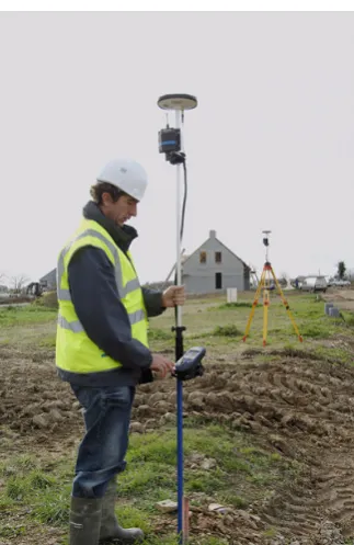
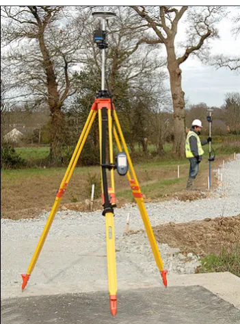
The ProMark3 (PM3) comes standard with a licence free 0.5 watt spread spectrum radio as shown in Figure 1.1, providing up to 1.6km line of sight communication. In built up urban areas it is limited to
[image:18.595.223.374.256.483.2]between 300 and 700 metres. With third party 2W radios that range can be increased to 2km in built up urban areas.
Figure 1.1 - ProMark3 with licence free 0.5 watt radio (Source: ProMark3 RTK White Paper 2007)
With the use of Continuously Operating Reference Stations (CORS) you can increase the operating range to about 10km. This is the recommended limit for single frequency RTK as beyond that distance dependent biases such as orbit error, ionospheric and tropospheric signal refraction can occur.
1.4
Conclusion
The focus of this research project is to test and improve the range performance of the ProMark3, by using Direct Internet Protocol (DIP) to transmit GPS and SBAS data. A rigorous testing regime will be conducted investigating latency, repeatability, efficiency and accuracy of the system. The use of Direct
IP software applications to transmit the data will also be explored.
Direct IP will be more prevalent with single frequency RTK because of the shorter range, but over Australia there are whole swathes of land that would currently be more than 50km from a CORS
network. With the investigation of a portable GNSS solution using Direct IP and with the affordability of the ProMark3, longer range RTK would be possible and very useful.
Having defined an approach for researching the problem to meet the stated aim and objectives, the next
CHAPTER 2 – LITERATURE REVIEW
2.1
Introduction
The purpose of this section is to conduct a review of literature into the use of internet protocols with Continually Operating Reference Stations (CORS) and Virtual Reference Stations (VRS).
The aim of the literature review is to explore the limitations of RTK GPS and provide a thorough understanding of the concepts behind CORS and VRS.
Research has been undertaken to investigate IP streaming for Real Time GNSS applications. Such IP streaming applications include Networked Transport of RTCM via Internet Protocol (NTRIP) and Direct Internet Protocol (DIP) which forms the major focus of this research project. Further explanation
is made about these two applications and then finally reviewing previous research and testing of those server applications by others.
2.2
Real-Time Kinematics (RTK) Surveying and limitations
Investigations began in the mid 1990’s to find the optimal way of processing reference receiver data, and then providing “correction” information to users, in real time. This practice is known as RTK Surveying (Rizos and Han 2003).
RTK positioning with GPS as shown in Figure 2.1, is a common survey technique used today. RTK GPS allows the use of a static ‘reference station’ with known coordinates, while the second ‘user’ receiver simultaneously tracks the same satellite signals. When the carrier phase measurements from the two receivers are combined and processed, the mobile user’s receiver coordinates are determined
Figure 2.1 - ProMark3 RTK System
(Source: Gemini Positioning Systems Limited viewed February 08,
http://gps1.com/magellan_promark3rtk.html)
With modern equipment only a few tens of seconds of data are typically required to fix the ambiguities associated with the GPS phase data observable and compute a baseline; the difference in latitude, longitude and height between the reference and rover positions (Higgins 2002). The ultimate
implementation of such a technique is known as ‘real-time kinematic’ (RTK), and is capable of cm-level accuracy under certain constrained operational conditions (Rizos, 2002).
One critical limitation of this conventional RTK approach is that the distance between the reference and rover receivers must be less than about 20km in order to be able to resolve the integer ambiguities
reliably ‘on-the-fly’ (i.e. in kinematic mode). This limitation is due to distant dependent biases such as the GPS satellite orbit error, and the ionospheric and tropospheric signal refraction (Zhang et al 2007a).
Wubbena et al (1996) maintains that RTK can provide centimetre position accuracy, though the
Classical RTK GPS requires that distances between the roving GPS unit and reference station should not exceed 10km to achieve a horizontal accuracy better than 10mm +/- 1ppm (HNTB 2004). This limitation on distance between the base station and mobile rover is due to systematic effects of
ephemeris, troposphere and ionospheric errors. These errors result in an increased initialisation time and reduced accuracy (Wubbena et al. 1996). For most surveying work the 10km range would be sufficient but when completing a survey that covers a large area and requires measurement of longer baselines, then these distance dependent errors become significant.
The limitations of RTK surveying have been highlighted and have led to the development of a system of networked reference stations.
2.3
Real Time Networks
2.31 Continuously Operating Reference Stations (CORS)
CORS are defined as GNSS receivers located permanently at sites having very accurately pre-determined coordinates. A CORS tracks GNSS satellites continuously 24 hours a day and may be an individual receiver (single base) or may form part of a group of receivers strategically located across a
region. Groups of CORS are referred to as CORS networks. Such networks may span areas of several tens of kilometres in dimension (i.e. Sydnet) as shown in Figure 2.2. CORS networks can cover larger regional areas, continental or even on global scale.
High quality GPS reference stations have been established, in a sparse global network, since the late 1980’s to support scientific applications such as tectonic/seismic research, geodetic
reference frame definition and maintenance, and for atmospheric studies (Zhang et al 2006).
These stations are located hundreds, or even thousands of kilometres apart. However, by improving the availability of reference station data for users that demand high positioning accuracy, reliability and integrity in real-time, the variety of applications can grow rapidly. CORS networks are therefore critical ground-based infrastructure enabling the basic utility of high accuracy positioning to become available to a diverse range of users (i.e. surveying, precision farming, structural monitoring, etc).
Zhang et al (2006), states that regional CORS networks are currently being established in many countries as part of the foundation for the spatial data infrastructure. The future may see CORS systems replacing permanent survey marks or geodetic trig stations which are used for precise surveys.
The distribution and density of a CORS network is constrained by the establishment costs per reference station, the area to be serviced and positioning accuracy requirements (Zhang et al 2006).
Existing CORS networks in countries such as Germany, UK, Denmark, Austria and Japan are
sufficiently dense to restrict the maximum baseline length between a user and a nearby reference station to be well under 40km (Zhang et al 2006), which is generally sufficient for cm-level accuracy techniques based on a single reference station, using high quality, dual frequency receivers that permit rapid “ambiguity resolution” (AR). However, as the inter - receiver distance increases, the residual atmospheric biases (due to differential ionospheric and tropospheric delay of the GPS satellite signals)
in the double differenced GPS observable increases, make AR more difficult (and even impossible using current rapid positioning techniques). Hence this distance constraint for rapid AR makes accurate positioning with respect to sparse CORS networks problematic, and this has profound ramifications in Australia due to its large area and relatively sparse population (Zhang et al 2006).
2.32 Network RTK
This allows a user not only to increase the distance at which the rover receiver is located from the reference, it also increases the reliability of the system and reduces the RTK initialization time. The concept can be used not only to set-up new networks, but also to improve the performance of old, established networks. The network error correction terms can be transmitted to the rover in two
principle modes namely;
1. A Virtual Reference station mode. This mode requires bi-directional communication. The basic advantage of this mode is that it makes use of existing RTCM and CMR standards implemented in all major geodetic rover receivers and thus is compatible with existing hardware.
2. A broadcast mode, in which the error corrections due to atmospheric and orbit effects are transmitted in a special format, which requires changes of rover receiver hardware or additional hardware to convert the non-standard format to a standard RTCM data stream before used by the rover.
2.33 Virtual Reference Station (VRS)
A virtual reference station is a simulation of a reference station. At any position in the network’s coverage area, the control centre can approximate the correction data that a reference station would send if it were located at that position. The control centre uses information from all other stations to
compute these corrections. VRS requires bi-directional communication between rover and the control centre. (Peterzon 2004).
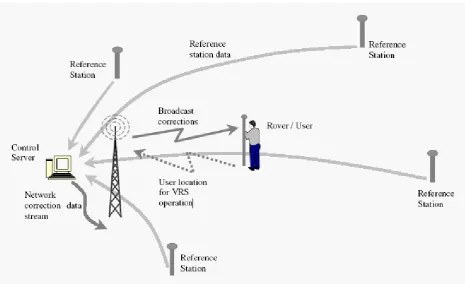
As you can see in Figure 2.3, the GPS rover sends its approximate position to the control center. It does this by using a mobile phone data link, such as GSM or GPRS, to send a standard NMEA position string called GGA. The control center will accept the position, and responds by sending RTCM correction data to the rover. As soon as it is received, the rover will compute a high quality DGPS
Figure 2.3 - Network RTK system and data flow (Source: Talbot et al 2002)
The network server will now calculate new RTCM corrections so that they appear to be coming from a station right beside the rover. It sends them back out on the mobile phone data link (i.e. GSM or GPRS). The DGPS solution is accurate to +/-1 meter, which is good enough to ensure that the
atmospheric and ephemeris distortions, modeled for the entire reference station network, are applied correctly.
2.4
Internet Streaming of RTCM via Internet Protocol.
2.41 Internet Protocols
The Internet Protocol (IP) is the method or protocol by which data is sent from one computer to another on the Internet. Each computer (known as a host) on the Internet has at least one IP address that uniquely identifies it from all other computers on the Internet. When you send or receive data (for
example, an e-mail note or a Web page), the message gets divided into little chunks called packets. Each of these packets contains both the sender's Internet address and the receiver's address. Any packet is sent first to a gateway computer that understands a small part of the Internet. The gateway computer reads the destination address and forwards the packet to an adjacent gateway that in turn reads the
destination address and so forth across the Internet until one gateway recognizes the packet as belonging to a computer within its immediate neighborhood or domain. That gateway then forwards the packet directly to the computer whose address is specified.
Because a message is divided into a number of packets, each packet can, if necessary, be sent by a different route across the Internet. Packets can arrive in a different order than the order they were sent in. The Internet Protocol just delivers them. It's up to another protocol, the Transmission Control Protocol (TCP) to put them back in the right order.
TCP/IP (Transmission Control Protocol/Internet Protocol) is the basic communication language or protocol of the Internet. It can also be used as a communications protocol in a private network (either an intranet or an extranet). When you are set up with direct access to the Internet, your computer is
provided with a copy of the TCP/IP program just as every other computer that you may send messages to or get information from also has a copy of TCP/IP.
TCP/IP is a two-layer program. The higher layer, Transmission Control Protocol, manages the assembling of a message or file into smaller packets that are transmitted over the Internet and received by a TCP layer that reassembles the packets into the original message. The lower layer, Internet Protocol, handles the address part of each packet so that it gets to the right destination. Each gateway computer on the network checks this address to see where to forward the message. Even though some
TCP/IP uses the client/server model of communication in which a computer user (a client) requests and is provided a service (such as sending a Web page) by another computer (a server) in the network. TCP/IP communication is primarily point-to-point, meaning each communication is from one point (or host computer) in the network to another point or host computer. TCP/IP and the higher-level
applications that use it are collectively are said to be "stateless" because each client request is considered a new request unrelated to any previous one (unlike ordinary phone conversations that require a dedicated connection for the call duration). Being stateless frees network paths so that everyone can use them continuously. (Note that the TCP layer itself is not stateless as far as any one message is concerned. Its connection remains in place until all packets in a message have been
received.)
Many Internet users are familiar with the even higher layer application protocols that use TCP/IP to get
to the Internet. These include the World Wide Web's Hypertext Transfer Protocol (HTTP), the File Transfer Protocol (FTP), Telnet (Telnet) which lets you logon to remote computers, and the Simple Mail Transfer Protocol (SMTP). These and other protocols are often packaged together with TCP/IP as a "suite."
2.42 Internet Streaming of RTCM
The Internet and associated applications and have seen explosive growth in recent years. Techniques
for the provision of multimedia content via the internet have become common place, examples being web-tv, MP-3 files, internet radio and web based telephone services. In addition to the availability of streamed content on the internet, mobile communication network providers have enabled the widespread availability of wireless internet access (Elmar LENZ, 2004).
With the growing possibilities of the Internet and the increase in the available bandwidth, applications like Internet-Radio or Internet-TV data streaming are becoming mature and stable.
The use of the Internet as a medium for transmitting GNSS code and phase corrections for real-time surveys has led to much research into this new idea.
advantage over radio transmissions. The user by is not bound to a limited range from the reference station, as long as the client has a connection to the Internet.
On the other hand, this method has some drawbacks such as high network latency times and sudden
disconnections from the server during the survey. Latency is surely one of the greatest problems, especially in RTK surveys, and is substantially tied to the data transmission rate, and thus the system used for connecting to the Internet (Pala et al, 2004)
The advent of wireless broadband service with its substantially higher data rate could enable new
techniques not possible previously to be used by GPS users (Yan.2004). Unlike voice networks, this technology is pure IP and is dedicated to data service. Wireless broadband has superior data rate compared to the three technologies mentioned previously. Its maximum speed is at around 1 Mbps which is almost three times that of 3G technology.
The main disadvantage of wireless broadband networks is that they are relatively new and their network coverage is nowhere that of voice networks such as GSM and CDMA. The iBurst network for example, is only available in metropolitan area of New South Wales, Queensland
and Victoria. Another network, Unwired, so far is only available in Sydney and now Melbourne. However, it is expected that as this technology gains popularity, their network coverage will expand and cover more areas. Part of this research project will investigate the use of wireless broadband to receive and to distribute RTCM data.
The transmission of differential corrections can be performed by 3 server applications. Direct IP server
2.5
Differential Correction Servers
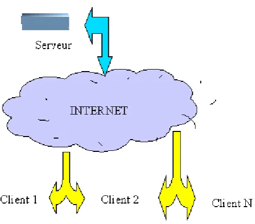
2.51 Direct IP
Direct IPis the main focus of this research and involves a single base reference station broadcasting corrections as shown in Figure 2.4. The station consists of a GPS receiver connected to a computer server via a null modem serial cable. The user connects to the server according to the IP address and TCP port number. This method can be used for CORS, VRS, FKP and SPIDER networks. You do not need a username or password. The provider of the corrections has no control or way of monitoring your
[image:29.595.174.423.351.570.2]usage. Hence Direct IP is usually provided for internal organizations.
Figure 2.4 - Direct IP Concept (Source: Utilserver Reference Manual, v1.7.0)
2.52 NTRIP
Federal Agency for Cartography and Geodesy (BKG) Germany, together with partners including the University of Dortmund and Trimble Terrasat GmbH. The main intention is using the “Internet” more or less as an alternative from the current existing real-time correction services provided via radio transmission (LF, MF, HF, UHF) or mobile communication networks like GSM, GPRS, EDGE or
UMTS. NTRIP is a generic, stateless protocol based on the Hypertext Transfer Protocol HTTP/1.1 and is enhanced to GNSS data streams.
NTRIP is used to connect a CORS, VRS, FKP or SPIDER system also. The provider of the corrections supplies you with a username, password, IP address and port number. The provider controls your
[image:30.595.155.442.352.594.2]access and knows when, where and for how long you are connected. This information can be used to monitor and charge for your usage. NTRIP has an extra layer of Protocol and is said to be slightly slower than Direct IP.
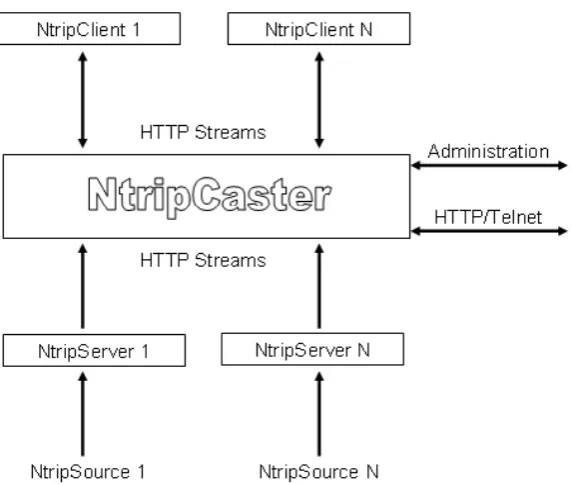
The basic system elements of NTRIP are the NTRIP Source, The NTRIP Server and the NTRIP Caster which are explained in more detail below.
NTRIP Source:
The NTRIP Source is a GNSS receiver that provides continuous GNSS data such as RTCM-104 corrections that refer to a known or specific location. A USA organisation, the Radio Technical Commission for Maritime Services (RTCM), works within a special Committee No. 104 (SC- 104) with standards for real time transfer of observations of satellite based navigation systems for differential applications. The special committee is responsible for RTCM
standards for differential GNSS. The HTTP-based TCP protocol NTRIP is currently undergoing this process via the special committee No. 104 to become a worldwide standard.
NTRIP Server:
In practice, the NTRIP Server is software running on a conventional PC that sends correction data from a GNSS receiver (COM-port) to a third installation (from NTRIP Source to
NTRIP Caster). NTRIP can be used within a virtual reference network where
the protocol is able to transport RTCM data. The RTCM corrections could be taken into
consideration at the users approximate position. This virtual reference station data is comparable with a NtripSource that could be transmitted by one of the Ntrip components, the NtripServer. The NtripServer transports GNSS data of an
NtripSource (GNSS receiver) directly to the NtripCaster. Before doing this in the described way the NtripServer sends a request to the mountpoint via HTTP 1.1. After the connection is
established the data can be send via TCP/IP. NTRIP Caster:
The NTRIP Caster is in general a HTTP server and acts, as already described, as a broadcaster integrated between the data sources (NTRIP Server) and the data receiver (the NTRIP Clients).
2.53 Mirror Mode (As developed by Utilserver)
When in Direct IP mode the reference station is generally near the server. In mirror mode the reference station is separate to server. As shown in Figure 2.6, the method allows the base station to broadcast its
corrections over the internet and the server can be in another country and still host multiple users. As this is beyond the scope of this project, I will not explain this method any further.
Figure 2.6 - Mirror Mode (Source: Utilserver Reference Manual, v1.7.0)
2.6
Internet Bandwidth
The term Bandwidth is often used to describe the amount of data that can be transferred to or from the website or server, measured in bytes transferred over a prescribed period of time.
Speed, for most sites, depends on the site being accessed and is related to the site's internet connection method, site capacity, number of concurrent users and data transmission load There is wide variability in rates among differing sites. One can often identify sites that are consistently fast in responding and
Speed also depends on the Internet network performance. Several well-known network slowdowns have occurred when Internet traffic was unusually high due to unusual news events. The efficiency also varies with the network loading throughout the day.
Figure 2.7 – Internet Congestion patterns - day versus night
(Source: http://www.myconnectionserver.com/whitepapers/solve_connection_speed_problems.html)
Figure 2.7, shows a number of speed tests extracted from the MySpeed Server database for a single user connection. This data shows a clear drop in service during daytime hours, which then improves
towards evening and returns to normal during the night. This type of pattern is typical of congestion, and would be an issue for your Internet Service Provider to address.
The Internet also assigns a route that passes from computer to computer to connect you with your
destination site. This route varies, depending on availability of the intermediate connecting sites. This route variation also contributes to speed variability.
Finally, there is the ISP's contribution to speed variability. The ISP has a bandwidth limit depending
2.7
Receiving correction data
There are currently two possibilities of sending correction data. It can be handled directly
from a single reference station or all observations from several reference stations used in a network can be forwarded to a central unit (server) for further processing before broadcast.
The user gets access to the internet using a modem (mobile phone) via a defined client software that streams DGPS correction data from a server to the mobile GPS receiver. The correction data needs to
be sent from the Server / PC via a wired Internet connection and then out to the rover utilizing a mobile radio network.
Users in the field have the choice to decide the technique for receiving DGPS or Real Time Kinematic
(RTK) through the Internet. They include GSM, GPRS, EDGE and in future UMTS.
Two popular choices are described as follows;
− GSM (Global System for Mobile communication) is a public digital cellular network using
techniques for multiplexing and using transmission band around 900 MHz. It is a worldwide standard. A GSM network can provide, besides telephony services, data communication in circuit and/or package mode. A more recent version uses an 1800 MHZ band (Europe) whereas a 1900 MHz
access network is running in the United States.
−GPRS (General Packet Radio Service): is a global system for mobile communication that increases the channel speed from 9600 to 14400 bits per second (bps), adding data compression. With GPRS, mobile data transmissions can be as fast as 115000 bps using the existing GSM base station infrastructure.
2.8
NTRIP / Direct IP – Research and Testing
There has been extensive field testing to check the achievable accuracy of NTRIP over conventional RTK and DGPS methods. Dammalage et al (2006) carried out observations during the period of March
to May 2006 using single frequency (L1), dual frequency (L1/L2) and handheld receivers. The accuracy was compared over different baseline distances and the results are displayed in Table 2.1 below.
Table 2.1 - Comparison of the observed accuracy according to the base-line distance (Source: Dammalage et al, 2006)
Base
Line
Trimble L1 Receiver Sokkia L1/L2
Receiver
Garmin eTrex
RAW Int
-DGPS
PP -
DGPS
Int -
RTK
Radio-
RTK
RAW
Int-DGPS
5km 0.602 0.532 0.586 0.162 0.161 3.4 4.5
15km 0.819 0.621 0.496 0.152 0.160 2.1 2.1
30km 1.926 0.340 0.416 0.158 0.160 4.0 2.2
60km 1.521 0.521 0.590 4.3 2.1
The table above compares the accuracy of differential corrected observations using conventional (post-processing and radio-RTK) and NTRIP with the uncorrected observations according to the baseline
distance. The results show that, with the Internet RTCM stream, all three different receivers show enhanced observation value than RAW observations and shows similar accuracy of observation with the conventional DGPS and RTK techniques (Dammalage et al, 2006).
Dammalage et al (2006) also found that the accuracy of an L1 receiver using NTRIP compared with
slightly and that it was possible to maintain an accuracy level of 0.5m at 60km. However, with baselines of 25 – 30km and beyond, it was found that it took nearly 30 minutes for initialization. This time applies for all methods.
Pala et al (2004) conducted tests using Direct IP and NTRIP. A delayed mode test was initiated to check the percentage of ambiguities fixed within a given number epochs, the percentage of correctly fixed positions and the time required to fix a given number of ambiguities. Tests were performed over 3 distances (10m, 3km and 15km).
The 10m tests allowed them to compare GSM and GPRS connections with an Ethernet LAN. The results favoured the GPRS over the GSM connection. At 10m both the NTRIP and Direct IP method compared equally.
The tests performed at 3km and 15km showed that NTRIP remained stable compared to the Direct IP
server. This is due to the automatic re-connection system of the NTRIP server. As the distances increased the time required to fix ambiguities remained constant using NTRIP.
Pala et al (2004) also compared latency of the LAN, GPRS and GSM communication methods.
A latency time of 1 – 2 seconds was found with the LAN, 3 -4 seconds with GPRS and over 7 seconds with GSM. A test for latency was also compared using GPRS with NTRIP and Direct IP. Results showed that NTRIP latency times were 1 – 2 seconds more than 50% of the time.
Chen et al (2004) compared performance of GPRS and GSM to conclude that the GSM provides a
more stable connection whilst the rover is moving at higher speeds. GPRS is a packet switched technology which also means that the more GPRS users connected to a base, the lower data rate is available. As GSM is a packet switched technology, the GSM data call has the same priority as a voice call and it is not limited by the GPRS capacity at the base station.
In the ProMark3 RTK White Paper 2007, Magellan tested the accuracy of the ProMark3 with different configurations and different baseline lengths. Presented in Table 2.2 are the field results obtained in an open-sky environment.
- Radio link between ProMark3 RTK base and ProMark3 RTK rover using Magellan radio modems. Baseline was 10 m.
- GPRS connected to a Z-Max Base station through Direct IP. Baseline was 2 km. The positions computed by the ProMark3 RTK rover were compared to the same positions measured with a Z-Max and post-processed with GNSS Solutions.
Table 2.2 - Fixed Solution Results (Source: ProMark3 RTK White Paper, 2007)
2.9
Conclusion:
Pala et al (2004) concludes that precision level obtained using the internet as a transmission medium
for differential GPS depends upon different factors such as the connection system and the protocol used. It was found that the stability of NTRIP was favoured over Direct IP and that the GPRS was preferred over the GSM connection as the GPRS is priced only on the amount of data that is downloaded whilst the GSM costs are time based.
With the different tests undertaken, it is evident that GPRS with NTRIP would be a good solution for GNSS data transmission over the internet. GPS surveying normally requires static or stop and go field procedures. NTRIP would provide a more stable connection when fixing ambiguities and GPRS would be more cost efficient for data downloads.
CHAPTER 3 – EQUIPMENT CONFIGURATION & DESIGN
3.1
Introduction
The purpose of this research project is to design a portable network GNSS data stream via the Internet with the ProMark3 and Direct IP. When you choose a location for a base station, you should look to achieve the following factors such as good security, clear open sky, good electricity supply & availability of fast & reliable internet.
The aim of this chapter is to outline the procedures conducted to design a portable home/office and a field based GNSS reference station broadcasting differential corrections using Direct IP. A continuously operating base station will be erected on my office roof in a rural area and a field base station will also be designed and erected in a safe and suitable location for testing purposes.
Chapter 3 will begin with a brief introduction to the ProMark3. Separate discussions will follow on the office and field designs including procedures involved in setting up the system, the choice of Direct IP program, setup costs, any initial problems and what I did to overcome them. Both designs will
conclude with discussions on other alternatives for design and implementation.
3.2
Project Background
The Magellan ProMark3 – An introduction
The Magellan Professional ProMark3 RTK GNSS is single frequency (L1), 14 channel, dual - constellation GNSS receiver.
Historically, RTK systems have used both L1 and L2. The difference between an L1 and an L1/L2 receiver lies in the number of carrier frequencies they can track. An L1 receiver tracks only one of three carrier frequencies transmitted by the GPS satellites whereas an L1/L2 receiver tracks L1, L2 and L2C carrier frequencies. Tracking three frequencies enables an L1/L2 receiver to achieve the same
Most L1 receivers are capable of achieving an accuracy of 1cm + 1 part per million (ppm), whereas most L1/L2 receivers are capable of a 5mm + 1ppm accuracy. However, L1/L2 receivers typically cost much more than L1 receivers.
[image:40.595.210.386.248.485.2]The ProMark3 RTK costs between $14,000 and $18000 AUD, depending on features and offering an economical alternative to more expensive L1/L2 RTK systems.
Figure 3.1 - ProMark3 (Source: PM3 RTK White Paper 2007)
ProMark3 RTK operates in two modes; base + rover and rover only. The rover can be connected to a real-time network through a web-enabled cell phone using Network Transmitted Real Time Corrections via Internet Protocol (NTRIP) and Direct Internet Protocol (DIP) .The second mode of RTK operation, base + rover as shown in Figure 3.1, employs a spread-spectrum radio solution that does not require a license or separate configuration integrated with ProMark3 RTK.
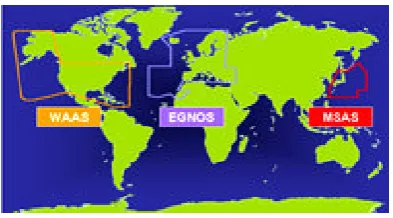
The ProMark3 also utilizes Satellite Based Augmentation System (SBAS) measurements which includes WAAS (Wide Area Augmentation System), MSAS (MTSAT Satellite Augmentation System)
WAAS/EGNOS/MSAS as displayed in Figure 3.2, all consist of ground reference stations that monitor GPS satellite data. Master stations collect data from the reference stations and create a GPS correction message. This correction accounts for GPS satellite orbit and clock drift plus signal delays caused by the atmosphere and ionosphere. The corrected differential message is then broadcast through one of
[image:41.595.200.397.270.379.2]two geostationary satellites, or satellites with a fixed position over the equator. The information is compatible with the basic GPS signal structure, which means any WAAS-enabled GPS receiver can read the signal.
Figure 3.2 - SBAS coverage (Source Track Logs Viewed Feb.08, http://www.tracklogs.co.uk)
In Australia the ProMark3 tracks the MSAS satellites 129 and 137.
Some of the disadvantages with the PM3 compared with more expensive receivers currently on the market include,
- Long range RTK (>10km) with L1 will require a long time to initialize and may not be possible. - Instant fix even for short baselines is not possible with L1 (single frequency).
- Partly shaded conditions can delay L1 RTK initialization times.
However the ProMark3 offers;
3.3
Design of a portable Office / Home based GNSS solution.
3.31 Antenna setup and connection to computer
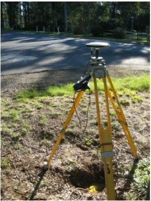
The ProMark3 NAP100 Antenna was setup on the roof of my office in rural north - west Sydney. The antenna’s final position was decided after placing the ProMark3 in several locations on the roof as shown in Figure 3.3 to see where it would detect the maximum amount of satellites. A Clinometer was
also used to measure the angle between the antenna and the nearest tree canopy. I found that all trees were less than 10 degrees above the horizontal which would allow good reception of all available satellites.
Figure 3.3 - ProMark3 base erected on office roof.
After settling on a position, an antenna mount was erected using an old prism pole and brackets secured to the wall to ensure that the mount would not move. By use of a prism pole, the antenna could be dismounted very quickly, making this design very portable.
After successfully erecting the antenna, I needed to run an antenna cable from the antenna to the GPS receiver. The ProMark3 comes standard with a RG58 coaxial cable 1m long as shown in this field setup in Figure 3.4.
Figure 3.4 – Typical Field setup showing ProMark3 with 1m long antenna cable.
Sagem Australiasia based in Sydney are the distributors for the ProMark3 throughout Australia. They kindly supplied me with 8m of RG58 coaxial antenna cable with a Male and Female TNC end. This cable would run down the face of the office and through the window attaching to the standard 1m cable and to the GPS receiver inside.
The ProMark3 is then connected to mains power via a power adapter to ensure it retains maximum battery power. For transfer of data, the ProMark3 uses a null modem serial cable to connect to the computer as shown in Figure 3.5. Modern computers these days have replaced serial ports with the faster USB port. If your computer does not support a serial connection then a serial to USB adapter
plug is necessary to overcome this problem.
The computer used for this project is running Windows XP and connected to Telstra Bigpond ADSL2+ internet on a 1500/256kpbs plan. A backup power supply was also attached to the computer which
To broadcast GPS corrections over the internet I used a freeware program called GPS3D. The particulars of this program will be discussed later in the dissertation.
3.32 The antenna cable problem and solution.
With basic understanding of how the base was put together, I needed to test the system to ensure it worked.
One of the first tests I conducted was to ensure the Promark 3 would actually detect satellites using the extension antenna cable. The ProMark3 comes standard with a 1m antenna cable and from email correspondence with Magellan in the United States and through Magellan message boards on the internet, it was unclear as to whether the antenna would work successfully using 9m of RG58 cable.
Little testing or information concerning this configuration had been conducted by any users of the ProMark3.
When I finally turned on the Promark 3, it didn’t detect any satellites. Sufficient time was given for it
to warm up and unfortunately no result.
I consulted Sagem again who supplied me with the cable. They responded by saying that the ProMark3 was probably not powerful enough to run the antenna alone over such a long antenna cable length. They suggested an alternative solution which was to use another GPS receiver with more power
connected to a GPS splitter box made by Rojone www.rojone.com.au.
Sagem supplied me with an Ashtech Dual Frequency Receiver, a GPS splitter box by Rojone and another 8m cable with female TNC ends to run from Antenna to splitter box. The standard 1m lead
Figure 3.5 – ProMark3 connected to Rojone Splitter Box and Ashtech Dual Frequency Receiver.
On the splitter box, the ProMark3 would be connected to the GPS ‘blocked port’ and only used for the controls onboard the GPS ( i.e. To start the base station) and the Ashtech receiver would power the antenna and connect to the GPS ‘through port’ on the splitter box. The antenna lead would plug into the antenna port as shown above.
After connecting everything back up, I turned the system on. The ProMark3 started to detect satellites. This was a great result however not the desired configuration for the experiment. I needed to find a way of just using the ProMark3 without additional help. One of the objectives of this project was to create a GNSS solution using only the ProMark3. If other users of the ProMark3 were keen to establish their
own base station, it would be nice if they didn’t have to purchase another GPS to help run the system.
I decided to disconnect the Ashtech receiver leaving the ProMark 3 attached in the GPS ‘blocked port’. To my surprise I was still retaining satellite signals. It wasn’t until I investigated the splitter box further
that I discovered it had been mislabeled. The ProMark3 was actually plugged into the GPS ’through port’.
Further research into the GPS splitter specifications revealed that the splitter box was actually passing
3.33 Direct IP Program - GPSD.
With the cable problem solved I moved onto the investigation of how I was going to broadcast GPS
corrections over the internet. The first thing I needed to do was find a program which would do such a thing. I found a freeware program called GPS3D through the internet at http://www.mgix.com/gps3d . GPS3D and its source code are in the public domain and freely available for download.
Within GPS3D is GPSD. GPSD is a daemon (program that runs in the background) that will monitor a
serial port for messages sent by a GPS device and broadcast it on a TCP port. It actually broadcasts anything that comes in on the serial port, so you could use GPSD to do an internet broadcast of any device (i.e. GPS, an atomic clock, an acquisition device etc.)
GPSD connects to Communication Port 1 (COM1) at 19200 bauds (baud rate) and broadcasts on
Transmission Control Protocol (TCP) port 2222 by default. These defaults can be changed if necessary. I couldn’t get it my computer running successfully with 19200 bauds and changed it to 9600 bauds.
After downloading GPSD, it is rather simple to operate. GPSD is a command line executable program.
The command prompt can be found under the Accessories tab within windows or by typing cmd in the ‘run’ section in windows.
Upon executing the command prompt, simply type gpsd –speed 9600 and press Enter. The program will start running and display the message as shown in Figure 3.6 below.
The message states “Please do not use for navigation”. The developer of this program has placed this disclaimer to warn you that you must use this program at your own risk. The intention was not for any real world navigation.
With such a warning users should take extra precautions and responsibility of results achieved using the program. Additional checks can be placed including measuring onto local control to ensure that the system is giving you the correct information.
I have based all my testing using this program. The overall performance, the number of users possible
at one time and comparison with another program called Utilserver, will be discussed later in the dissertation.
3.34 I.P. Address
Before we test to see that GPSD is broadcasting the GPS data, you need to find out your computers I.P. address. Several websites on the internet will tell you what your IP address is.
I used www.iplookup.com
An Internet Protocol (IP) address is a numerical identification (logical address) that is assigned to devices participating in a computer network utilizing the Internet Protocol for communication between its nodes. Your I.P. address will be four sets of numbers like this 220.101.34.96 and is normally allocated by your internet service provider.
Users who connect to the base to access data will need to know this address. The address is likely to change every time you restart your computer and should be checked every time you intend on using Direct IP. If you contact your internet service provider they may be able to assign you a Static I.P.
address which won’t change. Any changes to the address should be passed onto the people accessing your base especially if they access it on a regular basis.
A simple way to check that GPSD is broadcasting differential corrections to the internet is by typing the IP address of your computer and the port number 2222 into the internet browsers search bar as
Figure 3.7– Typing the IP address and Port Number in the Internet Search Bar.
Upon pressing enter on the keyboard, the webpage will display NMEA messages as a series of complex alpha and numeric characters. This is clear indication that GPSD is receiving data from your GPS and should work successfully in the field connecting with a GPS rover.
3.35 Port Forwarding
The first time testing this method outlined in Section 3.34, it failed. I discovered that is was due to the fact that the computer was connected through a router and sharing the internet connection with another
computer. I am using a NETGEAR DG834G wireless router. I am connected to this router with an Ethernet cable.
Each computer is assigned an IP address from the router. When the first computer is connected it will be given the IP address 192.168.0.2. The next computer will be given 192.168.0.3 and so on. This may be different for other router brands and so I refer only to using the NETGEAR router in this project.
This IP address is not the IP address that your internet service provider supplies you with.
Once GPSD has received the GPS data, it needs to export it out through port 2222 within your firewall. When a port is open, a service is assigned to it. Software ports are numbered connections that a
computer uses to sort types of network traffic. For security, by default, all ports to the internet and most LAN ports are closed so that traffic cannot flow through them.
What is Port Forwarding? Port Forwarding creates a `tunnel' through a firewall, allowing users on the Internet access to a service running on one of the computers on your LAN (Local Area Network), for example, a Web server. You need to be very careful when making a decision to put additional holes in your computers firewall so as not to invite any unwelcome visitors.
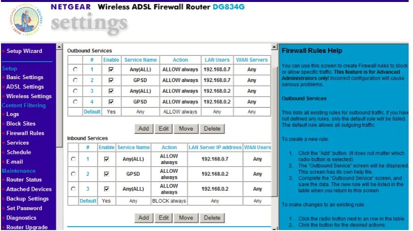
[image:49.595.54.480.253.491.2]To setup Port Forwarding, you need to configure the router. It will differ depending on the router you are using. You need to explore the firewall settings of your router as shown in Figure 3.8 below.
Figure 3.8– NETGEAR Router firewall settings
Upon assigning rules for the firewall, you should be able to successfully send GPS data to the internet. Simply retype the assigned IP address from your service provider followed by the port number and press enter on the keyboard. You should then see data appearing on the screen as explained earlier in
Section 3.34.
It may be useful to create 3 icons on your desktop. The first icon is a link to the command prompt. You can rename it GPSD. Secondly, you can create a link to the www.iplookup.com website so that you can find out your IP address quickly. It’s unlikely that the IP address will change but it’s important to
you to the screen as shown in Figure 3.7 previously. By having all three icons on your desktop this will help save valuable time getting the office or field base started.
This now concludes the design for the portable office based GNSS system. A few settings within the
computer and with the setup of the ProMark3 need to be achieved before the system will operate successfully.
3.4
Design of a portable field based GNSS solution.
3.41 A basic design
At the time of this project, little research has been undertaken into a portable field system using the ProMark3.
What is a portable system? You need to take the whole concept of the office base as described previously in Section 3.3 and bring it to the field. You therefore need to look at the practicality of such a system in regards to setup, security, portability, cost, usefulness and so on. I have explored the idea of bringing the office to the field and will discuss the problems I faced in detail.
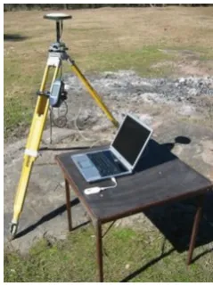
[image:50.595.237.357.536.697.2]What do you need for a portable system? In its simplest form you need a ProMark3 GPS with a Tripod, a laptop computer, a card table or something suitable for the computer to rest on and wireless broadband as shown in Figure 3.9.
The ProMark3 receiver is still connected via a null modem cable to the laptop computer which has Serial to USB adapter plug. The computer is equipped with the GPS3D software. Instead of fixed line broadband internet I am using wireless broadband. I’ve chosen to use a 3 Mobile Broadband Modem as shown in Figure 3.10 with a 2GB plan and speed of 1.5Mbps download and 384kbps upload.
Figure 3.10 – 3 Mobile Broadband Modem connecting to a laptop computer USB port.
3.42 Amendment to the basic design
With the basic setup as shown in Figure 3.9, the system relies entirely upon battery power. The laptop computer battery will last on average 1hr and with mobile broadband use this time may be even less because the broadband is powered by the computer. The ProMark3 will last for several hours on a fully
charged battery and can retain longer time if things such as backlight controls on the unit are turned off to avoid wasting power. Other things such as not having to use the UHF radios will assist in prolonging the battery life.
To maintain constant power supply to the ProMark3 and to the computer, I will use a Projecta 12V
Figure 3.11 - Projecta 12V 17Ah Sealed AGM Portable Battery with 300W DC – AC power inverter
According the manufacturers specifications you can run a 13W camping lamp for 16hours. I cannot
place comment on the performance of the battery, except to say that it retained enough power to operate all equipment successfully for a period of 5 hours without any complications. This could be further explored.
With a mixture of expensive equipment sitting alone for any period of time, one would wonder how safe it is. We face this situation in everyday surveying. We always leave tripods and equipment setup away from where we are working. It’s all part of the job.
This is one of the concerns raised for such a system. I installed a web camera (see Figure 3.12) to
capture live footage from the base. The footage could be seen either from another computer back in the office or via a web enabled mobile telephone.
Figure 3.12 – A web camera erected on a spare tripod.
As the footage is streaming live, the user will need to be prepared for any additional costs that might be charged to their wireless broadband service or viewing it from the office computer or mobile phone. The setup could be customized to update the photo every minute if desired.
I used web camera software from a website called Stickam. www.stickcam.com. They allow you to install a piece of java script code into any webpage which is linked to your webcam. As I was looking for the cheapest alternative for this system, I created a blog website. I called the website ProMark3
Security www.promark3security.blogspot.com as shown in Figure 3.13. Unscheduled outages on the website, program upgrades and website problems are all concerns associated with this and therefore 100% reliability cannot be guaranteed.
With all the pieces put together we have a portable GNSS solution (see Figure 3.14). To simplify the design I have replaced the tripod of the base with a bi-pod.
Figure 3.14 – The ProMark3 Portable GNSS Solution
Alternatives to this setup have been considered for security and wet weather conditions. With equipment ports exposed to the elements and without proper weather protection, damage could be caused to the entire system within a short period of time. Insurance of the equipment would be an
absolute necessity. It’s a requirement that businesses have public liability insurance to protect the public from any accidental injury from equipment.
Figure 3.15 shows another alternative to a portable solution using a car to store and protect the
Figure 3.15 – An alternative Promark3 Portable GNSS Solution.
The gear would be protected against the elements including rain however heat may affect the gear inside. Potential trip hazards could also be avoided if suitable barriers, witches hats or signs be erected
near the gear. As mentioned earlier, public liability insurance would be essential in this situation.
[image:55.595.171.424.481.708.2]Figure 3.16 shows the webcam footage from within the showing that it is possible to erect the base out of the elements.
This concludes the design for the portable field GNSS solution for the ProMark3. Security, power and
protection all play major roles in the effectiveness of the setup. Reducing the amount of gear needed to setup the system will assist in its portability. Possible solutions could be the use of a Pocket PC with internet capability to receive the correction data and broadcast it to the internet. The use of Bluetooth technology to transmit the corrections back to a computer inside a car may also help with security and hazards. Additional accessories of the ProMark3 include a magnetic car mount to erect the antenna to a
car or metal surface. This could be used for either base in the field or office. You could mount the antenna on a car, have your gear inside and post process the location of the base afterwards or alternatively before you start surveying.
3.5
Connecting the ProMark3 to the Internet and Direct IP
As discussed earlier, the use of the 0.5 watt conventional UHF radio has its limitations with the ProMark3. This is the main focus point of this research project. The ProMark3 has a limited working range of about 300 - 700m in built up urban areas and up to 1.5km for open areas in line of sight
conditions. Third party 2 watt UHF radios can improve the range of the ProMark3 however I will not be testing this in my research project.
The concept of Direct IP involves the use of a mobile telephone with Bluetooth capability connected to the ProMark3 rover a seen in Figure 3.17. The mobile telephone acts as a modem connecting the rover
[image:56.595.231.369.577.725.2]to the internet.
The rover can then connect to the base who is broadcasting its position over the internet. As long as retain your telephone signal, you will retain a connection to the base.
This allows a greater working range between the base and the rover. The mobile phone can operate
within range of any telephone tower. There are more and more towers being erected every day making it very easy to access data over the internet almost anywhere.
To establish a connection you must have a mobile telephone capable of connecting to the internet. I am using a Samsung SGH501 mobile with Telstra Wireless Broadband 3G.
Internet access comes with the phone plan. Associated costs with this are discussed later in Chapter 6 Section 6.5.
.
[image:57.595.212.384.331.547.2]
Figure 3.18