WATER LEVEL TANK USING FUZZY LOGIC CONTROLLER
MUNIRAB BINTI MOHD SALMI
A report submitted in partial folfllment of the requirement for the degree of Electrical Engineering in Mecbatrooic with Honour
Faculty of Electrical Engineering
UNIVERSITI TEKNIKAL MALAYSIA MELA.KA
YEAR
" I declare that this report entitle" Water Level Tank using Fui:zy Logic Controller" is the result of my own research except as cited in the references. The report has not been accepted for any degree and is not concurrently submitted in candidature of any other degree.
Signature
. ... £J ... .
Name:
m~~~~-~-.t?.~~
·
~···'~
:?.~
.~~~1''
" I hereby declare that I have read through this report entitle " Water Level Tank using Fuzzy Logic Controller" and found that it has comply the partial fulfilment for awarding the degree of Bachelor of Electrical Engineering ( Mecbatronic) with Honour"
Signature
Supervisor's Name Date
:
....
/.!:.~.~
...
..
.
.
:
N~~
.
.r~!~~~
...
~.1
.
1n\
..
!
~®
s
o
v;Rf\
1
II
ACKNOWLEDGEMENT
First of all, Alhamdulillah aI!ld praise to Allah S.W.T, I manage to complete my Final Year Project. I also would like to offer thanks and deepest gratitude from the bottom
of my heart for all the support, encouragement and inspirations I obtained throughout the
duration of this project. The help rendtered to us priceless, be it from the smallest of its kind to the largest
I would like to thank my supervising lecturer, Miss Maisarah Binti Mohd Sobran who gives me inspiration, supports and encouragement towards the success of my project.
I am also indebted to Universiti Teknikal Malaysia Melaka (UTeM) for funding and allowing me to be a part of the network and thus giving us a chance to gain useful knowledge and experiences.
In addition, 1 wish to express my sincere appreciation to my beloved parents, for
their Jove, encouragement and support me throughout the development of this project.
lii
ABSTRACT
Water Level Control is the most important element in the process control. Application of a
controller is widely used in industries especially for mould and die casting process and also
for the level monitoring of water in reservoirs. The most controller used in industries is
PID Controller, but the system is poor effected when the parameter in not chosen nicely.
On the other hand, by using Fuzzy Logic Controller, the control performances are increase
in time response and overshoot percentage. Jn order to get the accuracy on Level changes, a
simple work project water level sensor and water level controller based on Fuzzy Logic is
proposed. The hardware of the project is based on the suitable and simplicity of the tank
shape. The tanks used in the project were seal with water proof liquid to avoid the water
from flowing out. The experiment is conduct to find the resistance value in order to
complete the transfer function of the selection model of the tank. The Fuzzy Logic
Controller is select as the controller to control the system for accuracy of level in the tank.
'fbe technique use in this project is based on Takagi-Sugeno Method which are the
typically in the case of constant output. This method is selected due to the types of motor
pump that acting as actuator in the tank. All the range values at the membership function
and the rules table are decided based on the different of error and rate of change in the
tanks. The testing on the parameter level is consists of the microcontroller with and
without the fuzzy controller. At the end of the experiment, the differences between the two
experiments are shown. After implemented the controller into the system, the time
response had shown an improvement compared with non-controller adaption into the
system. The time response had shown the improvement from 8.74 second to 0.2667 sec for
rise time. Meanwhile for settling time improved from 24.2 second to 6.980 second. The
overshoot percentages from 4.32% to 0% with time peak 18 second to 7 second. The result
iv
ABSTRAK
Proses Pengawalan Air adalah sebuah proses yang amat penting didalam sesebuah sistem.
Proses in banyak digunakan secara meluas didalam industi terutamanya pada pros~:s
pembentukan acuan plastik atau besi dan proses kawalan terhadap empangan sungai atau
air. Pengunaan kawalan yang dinamakan "PJD Controller", amat meluas didalam sistem
pemgawalan paras cecair. Akan tetapi, pengawal ini akan mendatangkan kesan yang buruk
kepada ses1ebuah sistem sekiranya unsur-unsur yang terdapat pada pengawalan tersebut
tidak ikuti atau dipilih secara tepat. "Fuzzy Logic Controller" adalah salah satu pengawal
yang boleh digunakan didalam sistem proses pengawaJan paras air. Pengawal ini
memberikrun impak yang positif pada sistem dari segi kecepatan masa bertindak dan
ketepatan paras air yang telah ditetapkan. Didalam mencari ketepatan pada setiap
perubahan air, "Fuzzy Logic Controller" ak:an digunakan sebagai Pengawal di dalarn
projek ini. Bentuk Perkakasan yang digunakan didalam projek ini adalah bentuk segi
empat kerana ianya sesuai dan mudah. Kedua-dua tangka yang sama saiz digunakan dalarn I
projek ini haruslah ditampal dengan bahan kalis air bagi mengelakkan berlakunya
kebocoran. Terdapat beberapa ujikaji yang dilakukan didalam projek ini, seperti ujika.;ii
untuk mencari pemodelan matematik terhadap tangki ini. "Fuzzy Logic Controller" adalah
pengawal yang dipilih untuk dimasukkan kedalam sistem bagi pengawal paras air kelua.r
dan masuk. Teknik yang digunakao didalam "Fuzzy Logic" adalah teknik "Tagalaf
-Sugeno ". Teknik ini dipilih kerana nilai yang keluar pada motor pam adalah nilai yang
tidak: boleh dimalarkan. Setiap jarak: yang ditentukan didalam setiap keahlian dan peraturwn
adalah berdasarkan kepada perbez.aan nilai ralat dan nilai perbezaan perubahan air pada
tangki ters1ebut. Setelah pengawal ini dimasukan kedalam sistem, ujikaji terhadap
perubahan air dilakukan. Diakhir ujikaji ini meounjukkan perbezaan diantara sistem tanpa
pengawal dan sistem yang menggunakan pengawal "Fuzzy Logic'' Data yang diperolelll
rnenunjukan peningkatan terhadap masa peningkat dari 8.74 saat kepada 02667 saat, dan
masa perubahan meningkat dari 24.2 saat kepada 6.980 saat Nilai peratus dalam setiap
ketinggian data meningkat dari 4.32% kepada 0% pada masa 18 saat kepada 7 saat. Setiap
v
TABLE OF CONTENTS
CHAPTER TITLE PAGE
ACKNOWLEDGEMENT ii
ABSTRACT iii
TABLES OF CONTENTS v
LIST OFT ABLES ix
LIST OF FIGURE x
LIST OF APPENDICES xiv
I 1 INTRODUCTION 1
1.1 lntroduction
1.2 Motivation 3
1.3 Problem Statement 3
1.4 Objectives 4
1.5 Scope 4
2 LITERATURE REVIEW
s
2.1 lntroduction 5
2.2 Controller Selection Analysis 5
2.2. l Journal 1 5
Vl
2.2.3 Joumal3 8
22.4 Joumal4 10
2.2.5 Joumal 5 l l
2.3 Comparison System Selection 13
2.4 Summarize of the system 15
3
METHODOLOGY
163.1 Methodology 16
3.2 Overview Project 16
3.3 Project Flow Chart 18
3.4 Collection of Data 19
3.5 Hardware Development 19
3.5.1 Types of Tank 19
3.5.2 Motor Pump 20
3.5.3 Sensor 21
3.5.4 Relay Board 22
3.5.5 Microcontroller 23
3.6 Software Development 24
3.6.l Matlab Software 24
3.6.2 Simulink and Model-Based Design 24
3.6.3 Fuzzy Logic Toolbox 25
3.7 Performance Analysis 26
3.8 Experimental Setup
2
6
vii
3.8.1.1 Find Resistance Value 27
3.8. l.2 Equation of Transfer Function 29
3.8. l.2. I Physical Model of the System 29
3.8.1.2.2 Equation of Model System 30
3.8. l .2.3 General Equation Transfer 32
Function
3.8.2 Fuzzy Controller 33
3.8.2.1 Input and Output 34
3.8.2.2 Membership Function 36
3.8.2.3 Fuzzy Rule 37
3.8.2.4 Defuzzification 38
3.8.3 Testing Level Parameter 39
4 RESULT AND DISCUSSION 42
4.1 Introduction 42
4.2 Hardware Design 42
4.3 Circuit Diagram 46
4.4 Resistance Graph 47
4.5 SimuJation on Fuzzy Logic Controller 48
4.6 Experimental in Control System with Fuzzy Controller 52
4.6.J Result of water level in the tank 53
4.6.2 Comparison between with and without FLC 54
5 CONCLUSION ANDi RECOMMENDATION
REFERENCES
APPENDIX
57
58
61
ix
LIST OF TABLES
TABLES TITLE PAGE
2. l Comparison between 5 Journal Papers According to the Criteria 13
3.1 Data reading from Upper Tank 29
3.2 Rule Table of Fuzzy Logic 38
4.1 Comparison between PID Control !er and Fuzzy Controller 52
x
LIST OF FIGURES
FIGURE TITLE PAGE
1.1 The level of the liquid in the tank
l.2 A human can regulate the level at the sight tube to compare 2 the level h with desired point by adjusted the manual valve
1.3 Automatic level control system replaces the human with 3
controller and sensor to detect the level
2.1 Structure chart of two container water tank liquid level 6
control system
22 Comparison between simulation result of PID Control 6
and Fuzzy PID Control
2.3 Structure of single tank 7
2.4 The actual level and expectation level 7
2.5 The structure model of double bold water tank 8
2.6 The decoupling effect of presudo linear system 9
2.7 The simulation of inverse system and PJC Controller 9
2.8 The effect of the conventional PID method 9
2.9 The structure of level water tank model 10
xi
2.11 Comparison between filzzy control and PID control I I
2.12 Control system 12
2.13 Block diagram of controller in matlab 12
2.14 Output from labview 12
3.1 Modelling of level water tank process 17
3.2 The flowchart on project overview 18
3.3 lnteracting two tank system 19
3.4 Two tank non-interacting system 20
3.5 Submersible pump motor 21
3.6 Echo wave sending by the receiver 22 3.7 HC-SR 04 sensor using: at the water level tank system 22
3.8 A relay board with one channel 23
3.9 Arduino Uno 23
3.10 Matlab Logo 24
3.ll Environment in Simuliilk 25
3.12 The environment in fuzzy logjc toolbox 25 3.13 The experiment is conducted in order to find the resistance 28
value
3.14 The schematic diagram of two surges tank connected in 29
Series
3.15 The fuzzy logic architecture controller block diagram 33 3.16 Five membership function name as error in input 1 variable 34
xii
3.18 The output membership function between 0 and 1 36
3.19 The membership function with two inputs and one 37
Output
3.20 Overall input-output surface 39
3.21 Processes of testing the level parameter 40
4. l Upper tank dimension in mm and view 1n 30 43
4.2 Lower tank dimension in mm and view in 30 43
4.3 Side view of non-interactive tanks 44
4.4 Tank at the lower side and top side 45
4.5 Circujt diagram implemented in the tank system 45
4.6 Schematic diagram of Ultrasonic Sensor 46
4
.
7
The linear graph of head against flow rate 474.8 The Simulink block diagram of transfer function 48
4.9 The simulation of the system without controller 49
4.10 The Simulink block diagram connected with PIO Controller 49
4.11 The typically step response for second order of the system 50
with PID Controller adaption
4.12 Block diagram of fuzzy controller implemented into the 51
control system
4.13 The control response of the system with fuzzy controller 51
4.14 Block diagram with two different controller in system 51
4.15 The Two different graphs of PIO and Fuzzy Controller 52
4.17
4.18 4.19
Graph distance against time with fuzzy controller
The graph water level from sensor against time
Graph after Fuzzy Logic implemented in water level tank
system
53 54 55
LIST OF APPENDIX
APPENDIX TITLE
A
B
c
Source Code of Water Level using Fuzzy Logic Controller
Data before implemented Fuzzy Logic in the system
Data after implemented Fuzzy Logic in the system
xiv
PAGE
61
77
1
CHAPTER 1
INTRODUCTION
1.1 Introduction
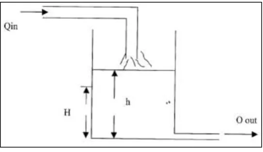
[image:17.595.169.441.473.630.2]The control system is a basic principle of logical and natural operations. Maintain the temperature, level and fluid flow rate in the system are the examples of the natural operation in the process of the control system. The addition of new technologies in the control system by replacing the human function came with the term of “Automatic Control” in the control action. The basic principle in Process-Control is to regulate the value of the quantity. By regards the dominants elements, the value of the quantity can be managed at the reference value or set point value. Adjust the Level of Liquid is the most similar example of system control that using the process-control principle.
Figure 1.1: The level of liquid in the tank
2
will drop or rise from the reference set point. In this process, shows the system does not provide any variable regulation to the reference value.
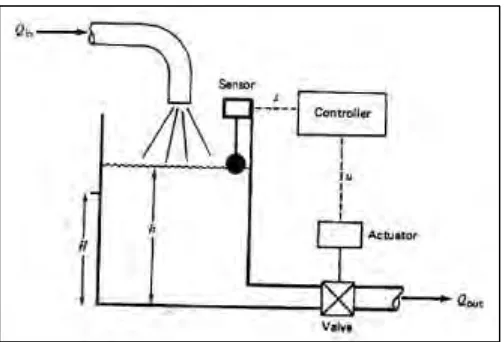
[image:18.595.171.441.340.502.2]The technology of artificial control was developed over the past decades by used humans as the controller action to the system. This system called as Human-Aided Control. The level of the water tank can be indicated by using sight tube Figure 1.2 to compare the level of the water (h). On the other hand, the flow rate of the output can be manipulated by adjusting the valve in order to change the water level using a human control. If the measured value is larger than the set point, the human opens the valve to a minimum in order to give the water filled into the tank until it reaches the set point H. This situation also happened when the water is smaller than the set point. The user acts as indicator to monitor the water level at the S tube.
Figure 1.2: A human can regulate the level a sight tube S to compare the level h, to compare the desired set point level, H and adjust a valve to change the level
3
Figure 1.3: Automatic Level control system replaces the human with the controller and sensor to detect the level
1.2 Motivation
Over the past decades, the research on computer control of manufacturing system has been extending as it requires a deep understanding on how to implement the complete system. The application of liquid level control has been detected in tank level gauging of milk, level gauging of acid, oil and level monitoring of water in the reservoir. Many industrial worldwide needs the process of liquid level control in order to improve the capabilities and efficiency of the production. [2]
For instances, water treatment plants are used by the industries to the kept the plants in a good and safe condition without any infection that caused by the excess water. That proves the water level controlling system is an important process that have to be managed some parameter values for the smooth running process in order to get the quality product. The process is possible upon controlling the level of water in the tank system. [3]
1.3 Problem Statement
4
in the industries, the Conventional PID Controller is used to indicate the level of the liquid in the tank system. The PID controller is used because of their reliable, simple and accurate in the closed loop feedback system. However, if the parameter of PID controller is not chosen nicely, it might have the poor effect to the system. On the other hand, by using Fuzzy Logic controller, the overshoot of the system is limited in order to have a great control performance.
1.4 Objectives
The Aim of this project is:
I. To design and tune the Fuzzy Logic Controller in Water level Tank System
II. Analysis the result of the Fuzzy Logic Controller performance (overshoot and the transient response) of the Water Tank System
1.5 Scope
5
CHAPTER 2
LITERATURE REVIEW
2.1 Introduction
In this chapter discuss the controller selection based on the 5 Conference Paper from IEEE sites. Controller Analysis based on the control performance that obtained from the graph and the complexity of the architecture to build the project. The control performance has to be included the transient response time, the overshoot percentage and the steady-state error of the system. The better control performance shows are decided the summarization of the controller selection analysis
2.2 Controller Selection Analysis
2.2.1 Journal 1: “Research on Application of Fuzzy PID Controller in Two -container Water Tank System Control” – Yan Zhao, 2010 [4]
6
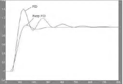
[image:22.595.180.427.257.428.2]is gradually increased curve with time constant against the changes of the water level. The second method used to design the adoption of Fuzzy PID Controller. By using this method, the end result came with 4 elements namely: Basic Domain of exposition, the Fuzzy domain of exposition, Fuzzy Set and the Quantization Factor. In order to make a fuzzy output inference synthesis of this design the method of weighted mean is implemented. The result of the liquid level control system of two container water is processing using Matlab Simulation Software. The graph is shown in Figure 2.2. The graph shows the satisfied achievement in over modulation quantity and steady state error performance.
Figure 2.1: Structure chart of two-container water tank liquid level control system
[image:22.595.177.433.476.651.2]7
2.2.2 Journal 2: “Fuzzy Adaptive PID Control Tank Level” – Qianhua Xiao, Deqiong Zou and Ping Wei, 2010 [5]
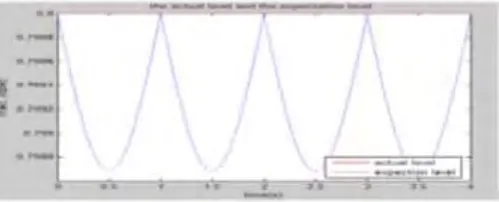
[image:23.595.187.421.485.573.2]In this conference paper, introduce the Fuzzy Logic Controller to control the unpredictable output of the water tank. The researcher states that using the Fuzzy Algorithm method and Fuzzy Adaptive PID Control method, the result can control the system up to 0.00008 squares of error in order to achieve the accurate and precise control. This Conference paper also describes the methods that are used to design the Fuzzy Logic Control of this system. In this system, the transfer function is rearranged from the first inertia principle of the single tank as shown in Figure 2.3 below. The most important method that the researcher used in designing the Fuzzy PID Adaptive control is the knowledge of experience to tune the three parameters, namely: proportion coefficient, integral coefficient and integral coefficient. In order to adjust the Fuzzy control, it must have the suitable Fuzzy Rule Table. The seven fuzzy set is the most established to control this system. The end of the result, the researcher presented the graph of actual level compare with expected level graph as shown in Figure 2.4. The analysis by using Simulink of plotting the comparison graph, the goal of this system is satisfied to achieve the accuracy and precisely up to 99.84% of error range 0.0013. The result is achievable to control the system of the liquid level in the tank.
Figure 2.3 Structure of single tank
[image:23.595.180.430.622.723.2]8
2.2.3 Journal 3: “Level Control System of Double-hold Water Tank Based on Inverse System Method and PID” – Hu Likun , Li Guangping and Huang Wenqin , 2010 [6]
[image:24.595.198.411.525.684.2]This Journal Paper discusses the combination method of the inverse system with PID controller in order to achieve the double-hold water tank control. The method of this system started with the determination of the model parameter. The structure of the modelling is shown in Figure 2.5 below. The output flow and the level are measured by using linear fitting and average method. After that, the inverse system method based on Iterator Algorithm is used to eliminate and simplified the equation of the mathematical model double-hold water tank. Next, in order to get the simulation of the Pseudo-Linear system graph, the inverse system must be connected with the tank in series form. The linearization and de-linearization graph is presented in Figure 2.6 below. This graph also proves that the inverse system is available to design the PID Controller. Since the graph is approved, the inverse system is lead to the close-loop transfer function of the water tank equation. The result of the transfer function is presented by plotting the graph on bode plot. The result shown the output signal of the inverse system is sent to the input of the actuator after the amplitude limiter reacted. As the conclusion, after done some adjustment time, the steady state error is reducing until less than 5%. Other than that, the system shows the fast response after the set value of level is changing. Figure 2.8 show the effect of using Conventional PID control method in this system.