Rochester Institute of Technology
RIT Scholar Works
Theses
Thesis/Dissertation Collections
4-20-1996
Implementation of computer technology for more
efficient industrial design processes
Kwang-Chul Ha
Follow this and additional works at:
http://scholarworks.rit.edu/theses
This Thesis is brought to you for free and open access by the Thesis/Dissertation Collections at RIT Scholar Works. It has been accepted for inclusion
in Theses by an authorized administrator of RIT Scholar Works. For more information, please contact
Recommended Citation
ROCHESTER
INSTITUTE OF
TECHNOLOGY
A
Thesis Submitted
to the
Faculty
ofThe
College
ofImaging
Arts
and
Sciences
In
Candidacy
for the
Degree
ofMASTER OF FINE
ARTS
Implementation
ofComputer
Technology
for
More
Efficient Industrial Design
Processes
by
Kwang-Chul
Ha
Approvals
Adviser: Mr. Craig McArt
Date:
5/2
Of
/.,~
Associate Adviser: Mr. Douglas Cleminshaw
Date:
"'.S
~ ~ ~/-z.q
Associate Adviser: Mr. Robert Keough
Department Chairperson: Mr. James H. Sias
Date:
~/%
I, Kwang-Chul Ha
, prefer to be contacted each time a request for production
is made. I can be reached at the following address:
9202 Buxton Drive
St. Louis, MO 63126
Contents
1. Introduction
1
2. New Trend
andRequirement
for the Industrial Designers
2
3.
Industrial Design
as aCreative
Tool
6
4.
The
Benefits
ofImplementation
ofCAID
8
A.
Compressing
the
Product Development Cycle
9
B.
Reducing
Product Development
Cost
13
C.
Increasing
Designer
Productivity
14
5.
What
to
Buy
andHow to
Buy
16
A.
Systematic
Approach for Hardware
17
a.1.
With Budget
17
a.
2.
Type
ofProcessors
18
a.3.
Testing
19
a.4.
Sample Checklist
20
a.5.
Hidden
Costs
23
B. Systematic Approach for
Modeling
Software
24
b.1.
Wire-frame System
24
b.2.
Solid
Modeling
System
26
6.
Computer Presentation Techniques
with3D
Models
32
A.
Scene Description
32
a.1.
Camera
33
a.2.
Light Sources
33
a.3.
Colors
33
B.
Rendering
34
b.1.
Shading
34
b.2.
Ray
Tracing
37
b.3. Texture
Mapping
38
C. Animation
41
7.
Rapid
Prototyping
43
A.
StereoLithography
45
B.
Selective
Laser
Sintering
48
C. Automated
Filament Extrusion
50
8.
Reality
check51
9.
Conclusion
53
Notes
55
1. Introduction
As
adesign
tool,
Computer
Aided Industrial
Design(CAID)
is
being
usedin
industry today
morethan
ever.Almost
everyonein
the
business
today
atleast
recognizesthat the ever-improving
power and sophistication ofCAID
can
help
compressthe
productdevelopment
cycle,
reducethe
development
costs,
andincrease designer creativity
and productivity.There
are,
however,
numerous systems availablewithdifferent
principlesand
applications,
andit
canbe very
time-consuming
andextremely costly if
the
designers
cannotfind
the
rightCAID
systemfor
the
job
at once.The
purpose of
this
paperis
to
guideindustrial designers
onthe
implementation
of various computertechnologies
andtechniques
in
order2. New
Trends
and
Requirements
for
Industrial
Designers
In the
1990's,
withcompeting
productsin
every
market segment -most produced with similartechnologies,
similarfeatures
andmaterials,
and almostidentical pricing
-design
may
soonbe the only
elementthat
differentiates
one productfrom
another.Industrial design is
notmerely
aline function. Industrial design
providesthe
essentiallink between
engineering,
manufacturing
andthe
marketplace,
andin
essence,
is the
primary
ingredient to
present andfuture
success.These
trends,
coupled with rapiddevelopment in information
technology,
create a
far
moreimportant
rolefor
industrial designers. It is
nolonger
Being
competitive as anindustrial
designer
will requireadaptability
and a progressive attitudetoward
productdevelopment. Companies
willhave to
reduce productdevelopment "cycle
time"to
quickly
get a productfrom the
drawing
board
to
market.It
will alsobe
necessary
to
generate acontinuous stream of new products
that
cantarget
market nichesfor
increased
marketpenetration,
marketshare,
andcompany image.
Designers
anddesign firms
willhave to be
adaptiveto
survive.Business
has
become
morecomplex,
requiring design
that
willsatisfy
abroad
range of constituentsfrom
stockholdersto
customers.In
response,
the
industrial design
professionhas
evolvedin
sophistication.Designers
today
workin
integrated,
multi-disciplinary
teams to
bridge
the
gapsbetween
marketing, engineering,
andmanufacturing,
whilethey
strivefor
creativeapproaches
that
will solve real needs.The
resultis both long-term
and short-termbusiness
success.Industrial design
is
a primeexample.Some
design
firms cling
to the
translate
them into
images
onthe
computer screenin
hours,
ratherthan
days
or weeks.Designers
today
areutilizing
suchtechniques
as surface or solidmodeling,
photo-realistic
rendering,
and rapidprototyping to
manipulate and presentdesigns.
This
greatly helps
clientsto
see what a productlooks like before
costly
changes are madeto the
materials,
dimensions,
characteristics,
orfunctionality.
Using
computersto
speedthe
wholedesign
processis
criticalto meeting
the
demands
ofdrastically
shortened productdevelopment
cycles.For
example, the
productdevelopment
cyclefor
new cars usedto
be
7 years;
today
it
approaches3
years.For
small,
uncomplicatedproducts,
companies used
to have 2 to 4
yearslead
time;
nowthey
had
better
introduce
those
productsin
ayearorless.
If
companiestake
longer
than
that,
technology
andmarketing
changes often makethe
product obsoletebefore it is
introduced.
Companies, therefore,
needto stay in touch
withcustomers
-asking
whatthey
want,
showing them the latest
3.
Industrial Design
as a
Creative Tool
Industrial
designers
providevisual communications and creativeinput for
product concepts and
ideas. Industrial
designers
help
customers visualizehow
their
businesses
can growthrough
productdevelopment
anddesign.
They
canbe
highly
influential in establishing the
use of a particularmaterial, process,
or product characteristic.Industrial
designers do
notlimit
their
workto
aesthetics or ergonomics of a product.They
createthe
identity
ofthe product,
being
intensely
involved
withthe
marketing
analysisof
the
product and market.Working
closely
withdesign
and applicationengineers, industrial
designers
identify
the
functionality
ofthe
productaffecting both assembly
and manufacturing.Designers
are a creative assetin
the
productdevelopment
process.Designers
contribute visual communications skills and creativeinput
that
providevisual
form
(two-dimensional
andthree-dimensional)
to
concepts and verbally-expressedideas,
features
andbenefits. Product
performancedefinitions
and objectives are refined and communicatedin
visualform,
ability
to
share visual andtechnical data
acrossdisciplines
viathe
computer encourages rapid product
development.
Therefore,
designers
should spend a greatdeal
oftime
keeping
up
withthe world,
with an eyetoward
developing
productsthat
fit
marketniches,
needs,
and/ordemands. The design
team
usesthis
expertisethroughout
the development
processto
concurrently direct the design
of new productsefficiently
and effectively.Much
ofthis
is
performedthrough the
aid ofhighly
sophisticatedCAID
software andhardware.
Technologies like
CAID,
when appliedto
the
productdesign development
process,
do
not require or motivate a change of organizational structure.They
do, however,
enhancethe
flexibility
ofany
type
of organization.CAID
makes
any level
ofdecentralization
easierto
implement,
asit significantly
improves the
communicationsamong
contributorsto the
productdevelopment
process.The
organizationsthat
fully
implement CAID
canmore
easily
pursue alternative sources ofconceptualdesign,
engineering,
4.
The
Benefits
of
Implementation
of
CAID
Implementation
ofCAID
variesfrom
applicationto
application,
but
the
following
benefits
are universal :A.
Compression
ofthe
Product Development
Time
Cycle
B.
Reduced
Product
Development Costs
C.
Increased Designer
Productivity
A.
Compressing
the Product Development
Cycle
Most CAID
usersfind
the
benefit
of speedthe
most visible and mostrewarding.
CAID
can givethe designers this
speedby
eliminating
time-consuming
processesandimproving
the
quality
ofdesign
by
using
3D
data
throughout the
productdevelopment
cycle.Within the
corporate environment,functional
departments
workless
independently
and moreinterdependently.
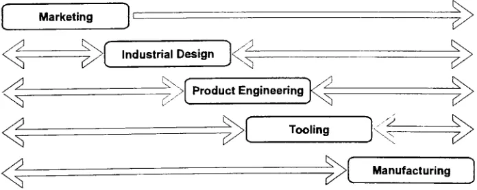
The linear
process ofindustrial
engineering.
(See Figure
1)
A
similar effect appliesto the design
consultant/client
form
of productdevelopment. With
CAID,
industrial
designers
can presentideas
and conceptsin
aworking
sessionwiththe
client,
instantly
making
changes on screen asthey
together
comeup
withdifferent ideas
or modifications.(See Figure
2)
Marketing
Industrial Design
ProductEngineering
Tooling
u
Manufacturing
Figure
1
.Traditional
design
processMarketing
-V
Industrial DesignS2- Product
Engineering
Tooling
, 'Z_
[image:14.557.245.341.268.473.2]Manufacturing
[image:14.557.121.469.528.667.2]Using
interactive
CAID
software,
the design
team
members canplay
withchanges
to
shape,
surfacequalities,
orthe way the
modelmay
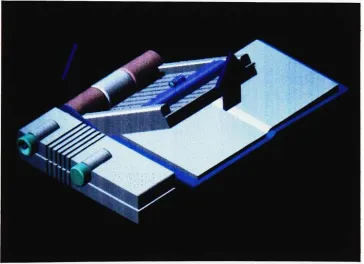
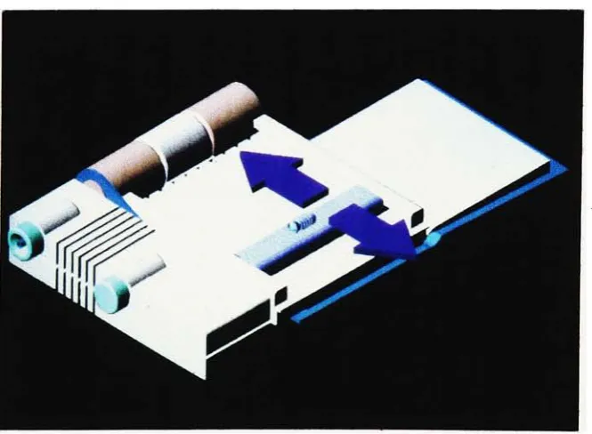
work.The
computer-generated model of
the
"Smart
Reader"shows
how the device
works.
(See
Figure
3 through
Figure
5)
With the
traditional
hand
rendering,
it
wouldbe
moretime-consuming
to
describe how it may
workasthe
designer
wouldhave to
render each andevery
scene.With the
help
ofCAID,
however,
the designer only has
to
rotateand movethe
desired
partsof
the
modelto
achievethe
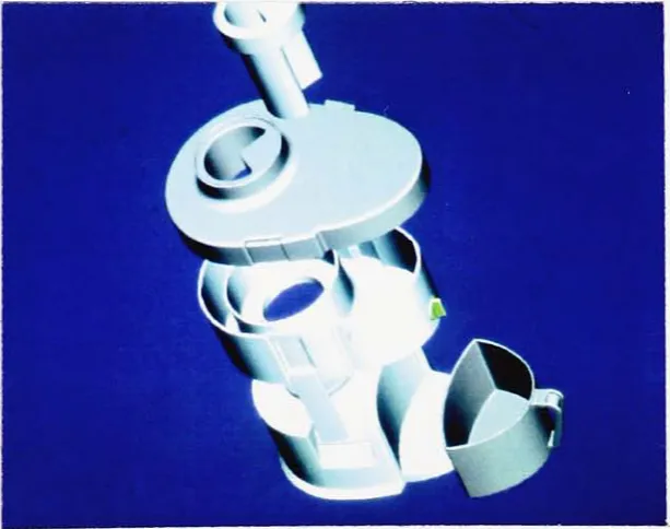
same goal.Figure 3. "The
smartreader"
[image:15.557.109.474.377.641.2]Figure
4.
"The
smart reader" [image:16.557.120.450.92.331.2] [image:16.557.123.456.407.651.2]Moreover,
CAID
can reduceunnecessary
andcostly
prototypedevelopment
withits
superbvisualizationcapability
to
produce photorealistic
images.
By
utilizing the
rapid computer generation of prototypes(i.e.
Stereolithography)
directly
from
CAID
data,
it
can also eliminatemanual process of
developing
3D
prototypeswhich couldtake
weeks andmonths .
Designers,
furthermore,
candirectly
pass3D data
to
andfrom
the
engineering department
andthe
modelshop,
eliminating the
reinterpretation of
design. This increased interaction
withinthe
design
team
in
combination withthe
abovebenefits
resultsin
greater speed andimproved quality
ofdecision-making.
Inovx
D3,
afull
service productdevelopment
company,
is
a prime example.The
company'sD3 group
(short
for
digital,
design
anddevelopment)
wasformed
to
providecomputerized product
design
andengineering
servicesthat
help
shortenthe
time from
initial
conceptto manufacturing
to
aslittle
asfour
weeks."Not only did
we save our clientmoney in
tooling
and othercosts,
but
wealso saved
them
atleast
two
months ofrework."
said
Anthony
Chan,
the
company's president.
"With
our computersystem,
we can offer clientsB.
Reducing
Product Development Cost
Daewoo
Motors,
one ofKorea's
leading
automanufacturers,
utilized aStereoLithography
apparatus(SLA)
in the
vehicleprototyping
stage oftheir
car
development
process anddiscovered the
benefits
ofearly design
verification,
shorterlead
times,
and effective use ofbudgets. Daewoo
Motors
reducedlaunch time
onthe
newEspero
sedanby
25
percent.Daewoo
cut costsby
employing
aStereoLithography
Apparatus
extensively.
It
built
over120 SLA
partsfor Espero in only
2.5 months,
including
consoles,
ashtrays,
anddoor
trim.
2In
the
corporate environment, much ofthe
cost savingsis
quantifiedin
terms
ofthe
elimination of expensive research andprototyping
ofborderline design
concepts.CAID
can reducedesign flaws early in
the
product
development
stage withits
realistic and accurate3D
models.Its
models and photo-realistic
images
canbe
usedin
implementing
marketresearch
early in
the
productdevelopment
process.The increased human
communication
facilitated
by
CAID
often resultsin lower
costs andbetter
C.
Increasing
Designer
Productivity
Garden
Way, Inc.,
aleading
producer of outdoor power equipmentbased
in
Troy,
NY,
implemented
CAID in 1991
asit
recognizedthe
needfor
aCAID
systemto
streamline productdevelopment.
The
mostdifficult
task
for
the
design
andengineering
team
atGarden
Way,
Inc.
wasthe
ChipperA/ac's
plastichousing.
Curvaceous,
cavernous,
and
highly
asymmetrical, the
housing
anchorsthe
unit'sbattery,
rotor,
fan,
engine,
wheels,
transmission,
and collectionbag,
all ofwhich mustfit into
specially designed
compartments.Using
the CAID
system,
Garden
Way
designed
the
housing
with3D
clarity,
and exportedfiles
to
ANSYS for finite
element analysis andmold-filling
analysis.Garden
Way
then
sentthe
finalized CAD files
to
vendors, whosetooling
was expeditedby
the
accuracy
ofthe
file's
geometry.The firm began
prototyping,
followed
by
endurancefield
testing
and productionin
recordtime.
"We
saved morethan
a yearin
development
and productiontime
using CAID
system"said
Peter
Sawchuk,
the
company'svice president ofengineering.3Companies
implementing
CAID
are positionedto
respondto
marketParticularly
in
industries like
jewelry,
eyewear,
and accessories, wherenew productsare released
every
few
months,
CAID helps
the
companiesmanage
the tremendous
workload.
Furthermore,
in
instances,
whenthe
designers
arelocated in
one spot whereasengineering
andmanufacturing
facilities
arelocated
in
otherless
expensiveregions,
CAID
as acommunication
tool
between
them
canpay
outin
a single season.Overall,
working in
three
dimensions helps designers
communicatedesign
information
moreeffectively
and canultimately be
more productive as3D
data
is
passedfrom
CAID to CAD
andback
againduring
redesign.Another
advantage ofCAID in
increasing
productivity is
that
designers
cancreate more
design
alternativesbecause CAID
tools
reflectthe
designer's
changes
to
form
or surfacequalitiesinstantly.
Also,
designers
canbe
more productive
by building
on previousdesigns using
alibrary
ofshared,
5.
What
to
Buy
and
How
to
Buy
With today's fast
changing
technologies,
comparing
the
performance ofthe
many
software andhardware
platforms,
especially those
madeby
different
vendors,
canbe
atough
assignment.Individual
machines perform sometasks better
and othersworse,
soit is
hard
to tell
how
allthe
variousfactors
(CPU, I/O,
graphics, caching,
etc.) play
together
whenrunning
today's
complexCAID
applications.Some
applications require moreRAM,
others
demand better
andfaster
graphics capabilities.In
general,
computer
technologies
areadvancing
atsuch afast
ratethat
it
is
almostinsignificant
to
mention what systemto
buy
now sincetoday's
best
andfastest
machinewill soonbecome
obsolete.The
price and performance gapsbetween
UNIX
workstations andpersonal computers
(including
IBM-PC
compatibles andMacs)
has
narrowed
in
recent years.Many
CAID
softwarepackages aredesigned
to
run on
less
expensivePCs
andto
achieve almostthe
same goals.However,
most ofthe
seriousCAID
applications runonly
onUNIX
platforms made
by
such companiesasSilicon
Graphics, SUN,
dollars
depending
onconfigurations-most of
today's
applications require128 MB
ofRAM
and atleast 1
GB
ofhard disk
space astheir
standardconfiguration.
The
softwarecosts are comparableto
hardware
costs,
andin
some cases are more.Thus,
designers
and organizationshave to take
avery
careful approachto
make a wiseinvestment.
A.
Systematic
Approach for Hardware
The
best
way
to
avoid chaosin this
situationis
use a systematic approach.A little
preparation and effortwillpay
enormousdividends
and willeliminate
the
possibility
oflosing
time
and money.A
checklistof requiredand optional workstation characteristics
is
needed asthe
basis for the
evaluation.
A list
ofcommonly
used peripherals shouldbe
maintainedin
anup-to-date manner.
If
available, the
set ofbenchmark documents from
each vendorshould
be
obtained.The
following
guidelines are an example :a.1.
With Budget.
When
budget becomes
available, askthese
simple questions :in-house
?
2. Have
youdefined
a set ofmandatory
requirementsthat
mustbe
addressed
by
allcompeting
proposalsbefore
they
canqualify for the
remainder of
the
benchmark ?
3.
Is
the
goal ofthis
acquisition a smaller number ofhigh-end
workstations,or
is it
alarger
number of mid-range orlow-end
workstations? Which
is
moredesirable ?
a.2.
Type
ofProcessors.
The importance
ofworkstation performanceis
undeniable.Depending
onhow
a system willbe
used,the
performance measurements canbe broken
down
to
the
following
categories1
.I/O
performance, whichis
the
rateofthe
system can movedata
into
andout of
the
system,typically
from
disk,
is important
This
canbe
expanded
to include
rates atwhichthe
system can access networked2.
Graphics
performanceis particularly important
in
amodeling
andrendering
system.Performance
canbe
affectedby
a number ofdisplay
pixels and color maps.
With very
complexrenderings,
it
could mean adifference between
afew
minutes and afew hours.
3.
Floating
point performanceis
crucialto
amodeling
system.Floating
point and graphics performance of a workstation are
the
best indicators
of overall performance
in
most ofthe CAID
system'smodeling
environment.
a.3.
Testing
Making
adecision based only
on paperstudy
canlead to
faulty
conclusions.
There
is
no substitutefor
hands-on
testing
andrecording
ofactual results with
files
oftypical
complexity.Suggested
testing
is
:-
Record
elapsedtimes
for
retrieving,storing, regenerating,
andrendering
a.4.
Sample Checklist
The
following
is
alist
ofsuggested check points1
.Describe
anddemonstrate
the
userinterface,
built-in
editor and screendump
capability.2.
Describe
the
ability
to
customizethe
userinterface.
3. Demonstrate the
ease of use of extensionsto the
interface,
cut andpaste
between
windows andthe
use ofthe
various shells available.4.
Describe
the
ability to
monitor systemconfiguration,
usage and eventssuch as
-
Disk
spaceavailability,
with alarms when a givenlimit is
reached.-
Tools
to
distribute
files
acrossthe
network.-
Methods
to
add peripherals.Management
of printqueues.-
Configuration
ofserial ports.5.
Evaluate
the
ease of use and completenessofthe
writtenmanuals/documentation.
6.
Evaluate
the
support ofthe
network system.7. Look
at utilitiesfor disk
partitioning.8.
Evaluate
the
vendor's policiesfor the
maintenance and supportof
the
hardware
and software.9.
Evaluate
policiesfor
maintenance responsetimes
and reimbursementfor
excessivedowntime.
10.
Evaluate
the
training
classes.1 1
.Examine
the
upgrade pathfor
the
CPU
and graphics engine.12. Examine
the
local data
backup
methods.13. Consider
the
optionsfor the
presentation methods.14. Provide
a completelist
ofthird
party
software supportedon
the
workstations.16.
Consider PC
andMac
support andinterface
issues.
17.
Evaluate
the different types
ofinput devices
such asthe
mouse,
the
tablet,
the dial
control unit orthe SpaceBall
.18.
Evaluate
erase-on-deletefeatures
ofdisk.
19.
Examine
support of peripheraldevices
such as :
-Paper/Transparency
-
Film/Microfiche
-
Magnetic Media
-SLA
-
Virtual
Reality
-
Monitors
20. Support
ofstandards-
Communication
-
Graphics
-
Database
-Operating
Systems
The
last
two
items
shouldbe
significantly
refinedto
accommodatethe
requirements
for
each site.Each
site shouldhave its
own substantiallist
ofother
necessary features.
a.
5. Hidden
Costs
A factor commonly
overlookedis the
hardware,
software andoperating
system maintenance
fees.
Most
vendorsintroduce
new versions oftheir
software and
operating
system once ortwice
a year.In
orderto
keep
current with
the
latest
version ofsoftware,
it is
a goodidea to
purchasemaintenance agreements provided
by
the
vendors.This is
aless
expensive
way
to
do
that,
asthey
charge alot
morelater if
youdo
nothave
the
valid maintenance contract.Since
these
costs can skyrocket,however,
they
mustbe included in the
quote and
factored into
the
price points and negotiations.Most
workstations comewith a
full
one-year warranty.The
second-yearmaintenance costs can cause your
department to
drop
support.It
is
aB.
Systematic Approach
for
Modeling
Software
Unfortunately,
it
is impossible
to
find
a perfect software solutionfor
aCAID
system.A
system with excellentdrafting
capabilities might nothave
goodmodeling
capabilities.An
excellentmodeling
software mightlack
a photo realisticrendering
capability
that many designers hope to have for
their
presentations.
Another
problemis
that
CAID
systems are notvery
wellintegrated
withthe
softwarethat
performsdownstream
processes,
such asdrafting,
finite
elementanalysis,
and numerical controltool
path generation.The
best way to
solvethis
problemis
to
integrate
aCAD
systemthat
has
good
modeling
anddrafting
capability
with a visualization system.The
following
categories are a guidefor
evaluating
amodeling
system :b.1. Wire-frame
systemThis
is
the
simplestway to build
a3D
computer model.In the
construction ofthe
wire-framemodel,
the
edges ofthe
objects are shown aslines.
are curved
surfaces,
contourlines
canbe
addedto
indicate
the
contour.The image
assumesthe
appearanceof aframe
constructed out of wire [image:30.557.185.376.233.454.2]-hence
the
name "wire-frame" model.Figure 6. Wireframe
representation of a refrigerator.There
arelimitations
to the
models which usethe
wire-frame approachto
form
the image.
These limitations
areespecially
pronouncedin the
case ofthree-dimensional objects
because
all ofthe
lines
that
define
the
edges(and
contouredsurfaces)
ofthe
model areshownin the image.
The lines
that
indicate the
edges atthe
rear ofthe
model showright
through
the
foreground
surfaces.This
can causethe
image
to
be
somewhatconfusing
to
the
viewer, andin
some casesthe
image
mightbe
interpreted
in
severaldifferent
ways.This
problemcanbe
solved withthe
hidden line
removalThere
are alsolimitations
withthe
wire-frame modelsin the way different
CAD
systemsdefine
the
modelin
their
owndatabases. For
example,
there
might
be
ambiguity
in the
case of a surfacedefinition
asto
which side ofthe
surfaceis
solid.This
type
oflimitation
preventsthe CAD
systemfrom
achieving
a comprehensive and unambiguousdefinition
ofthe
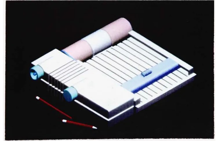
object. 4b.2.
Solid
Modeling
systemAn improvement
overwire-framemodels,
both in terms
of realismto the
userand
definition
to the computer,
is
the
solidmodeling
approach.A
solidmodel can
be defined
as a geometric representation of abounded
volume.In
this approach, the
models aredisplayed
as solid objectsto the
viewer,
with
very little
risk ofmisinterpretation.Unlike
wire-framemodels,
designers
canactually
treat the
solid modelsin the
sameway
they
wouldwith
clay
orfoam
models.They
cancut,
bend,
drill
ahole
or performany
other manipulation
to
the
model onthe
screen.This feature
in
solidmodeling
systemslets
industrial
designers easily build
a complete modelwith material
thickness
(see figure
7)
when required.This
process wouldbe
very
tedious
andtime-consuming
with a wire-framemodeling
systemMoreover,
sincethe
solid models contain materialinformation,
it
is easy to
check all
kinds
of material properties such asvolume,
center ofgravity,
interference
checks,
etc.These
characteristics of solidmodeling
allowthird
party
vendorsto
develop
morehighly
sophisticated and automateddownstream
applicationswhich makesthe
transition
between
designers
[image:32.557.126.433.318.560.2]and engineers more effective.
Figure 7.
Exploded
viewof solid-model parts.However,
solid models require a greatdeal
ofcomputationalpower,
in
terms
ofboth
speed andmemory,
in
orderto
operate.The
advent ofof
the
neededcapacity
to
meetthis
requirement.Thus,
we can expectto
see more and moreapplications of
this type in the future.
b.3.
Surface
Modeling
systemSurface
modelers arewidely
being
usedin
the
automotive and aerospaceindustries. A
majordifference
between
solid modelers and surfacemodelers
is the
absence oftopological information
connecting
the
surfaces.
Surface modeling
systems alsolack the capability
to
describe
the interior
ofthe
part.The
surfacesthat
are generatedby
surfacemodelers
have
zerothickness.
However,
surface modelers are capable ofdescribing
very
complex surfaces wheremany
solid-based systemshave
trouble.
Unlike
solidmodeling
systemswherean ambiguousdescription
ofgeometry
is
notallowed,
non-ambiguity
is
not a requirementfor
a surfacemodeling.
Individual
surfaces are assembledto
form the
desired
shapes.Although
the
entire surfacesmay
appearcorrectly
onthe
screen,
there
could
be
the
existence ofunclosed surfacesin the model,
especially
whereone surface meets
the
other.This
can present a problemif
and whenthe
b.4.
Parametric modeling
system :The Ultimate
in
Modeling
Systems?
The
"parametric"or"variational"
modeling
technique
brings
a newlevel
ofintelligence
to
design
automation.With
other methods ofmodeling,
smalldesign
changes often meanstarting
all over.However,
the parametric,
dimension-driven,
models allowdesigners
to
assign "special"dimensions
that
controlthe geometry
asthey
model(see figure
8).
These dimensions
can
be fixed
values,
formulas that
reference otherfeatures
ofthe model,
orcan reference control
dimensions
set atthe design
managementlevel. If
adesign
changeis
required,
designers simply
assign adifferent
set ofdimension
values which causethe
modelto
automatically
adjustits
shapeaccordingly.
[image:34.557.138.440.433.656.2]This
parametricfeature has
a great potentialfor
industrial
designers
because
they
do
nothave
to
be
concerned aboutthe
final
shapewhenthey
start a model.Industrial designers
canbegin
withavery
genericshape with no exact
dimensions,
then
refinethe
geometry
at alater
stageof
the
design
processby
changing
a numerical value or a geometricalrelationship.
This
also meansthat
industrial
designers
willeasily be
ableto
develop
variations of adesign
withouthaving
to
model eachtime.
Another
advantage ofa parametric systemis
that
it
capturesthe
design
intent. Design intent is built
into
the
modelby
specifying
the
rules andobjectives
that
governthe
creation ofthe
design. This
processinvolves
dimensioning
the
modelin
away
that
describes
the
interdependencies
rather
than
putting in fixed
values.This
can automatemany tasks that
withother systems must
be done
manually.Such
tasks
include
modifying
adesign
andits
manufacturing
instructions
to
meet newdesign
requirements,
generating
families
of parts orassemblies,
substituting
onepart
in
anassembly
for
another,
andassembling
componentsthat
arecreated separately.
Another important feature
ofthe
parametric systemis
associativity.Since
the
models,
they
canautomatically
generatefully
dimensioned
two
dimensional
drawings
from the
solid models atany time
during
the design
process.
All
drawings
associated withthe
models referencethe
solidmodel rather
than
it
being
copiedinto
the
drawing. This
meansthat
any
modifications
designers
may
maketo the
solidmodel,
2D drawings
willautomatically be
updated or viceversa.This
unique characteristic ofthe
parametric system allows
industrial designers
to
spend moretime creating,
not
drafting.
Furthermore,
this
singledatabase
ensuresthat
everyoneworking
onthe
projecthas
the
most current revision andthat the
effects ofthese
changes are not overlooked.Today,
most advancedCAID
systems arestriving for
the
ultimate systemby
combining
solid and surface generation with parametricfeatures into
6.
Computer Presentation Techniques
with3D Models
Seeing, they
say,
is
believing,
andin
mostbusinesses
it is necessary for
people
to
believe
with alltheir
hearts before
they
willinvest money
andtime in
a project.This is
one ofthe
biggest tasks for industrial designers.
However,
how
do
you seesomething
that
does
not exist?Answer
: render.Rendering
is the
process ofadding
color,
texture,
the
illusion
oftransparency
orreflectivity,
and othervisual effectsto
3D
models.Some
designers
preferto
use computerrendering instead
oftraditional
methodsbecause
they
wantahigh-tech look.
Others
useit because
ofthe
efficiencies realized.
A.
Scene
Description
Once
3D
objectshave been
defined,
the
nextstep
is
to
organizing
them
to
describe
a scene.This involves placing lights
to
illuminate
the
objects'
surfaces and
determining
the
viewby
selecting
a camera position andlens
type.
The
main purpose of scenedescription is to
setthe
stagefor the
nexta.
1
.Camera
The
camerain
rendering
softwareis
designed
to
mimic a real-worldcamera,
with alens
through
whichlight
rays converge at afocal
point andfocus
onto animage
plane.Users
can changethe
field
of viewby
eitherimitating
different
cinelenses
orchanging
the
field
of viewby
degrees.5By
andlarge designers
can positionthe
camera anywherein
the
scene.a.
2. Light
Sources
The
light
sourcesin rendering
packages alsoimitate
actuallighting
situations.
The
three
most commonlighting
types
areambient,
directional,
and radial.
Ambient
light is
non-directional,
distributing
light uniformly like
sunlight on an overcast
day. Directional
light
sources mimicthe
effect ofspotlights,
withtheir
cone-shapedspread,
ordirect
sunlight,
whichhas
adistinct,
parallellook. Radial lights illuminate from
one spotbut
notin
aspecific
direction,
like
alight
bulb.6The
colorsofobjectsarenormally determined
by
assigning
combinationsofcolored
lights,
notby
painting.Users have
the
optionsto
set multiplecolored
lights
that
canbe
positioned relativeto
the
objects.B.
Rendering
Generally
speaking,
there
arethree
categories ofimage rendering
techniques
usedin
CAID
systems :shading,
ray
tracing,
andtexture
mapping.
Industrial designers
often usethese
methodsin
combinationto
create a
desired
look in
the
most economical way.b.1.
Shading
There
aretwo types
ofshading
:Gouraud shading
andPhong
shading.All
rendering
software andmany CAD
programs offerthese techniques.
These
shading
methods are allillumination
modelswhich meanthat
they
describe only
the relationship between the
surface shape of an object andthe
color anddirection
ofits
lighting.
Thus,
for
example,
objects renderedGouraud
Shading
With
Gouraud
shading,
whichis
sometimes calledflat
shading,
eachfacet
of an object
has
the
same color at all points.It
shows gradation of coloracross a surface and some cases a rough approximation of
transparency.
This
technique
is normally
usedfor
quick visualizationduring
the
modeling
process
because
it is the
simplest andfastest (see figure
9
&
10
for
example).
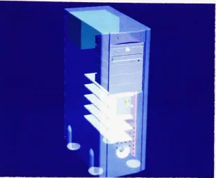
Figure 9. "The
smartreader"
[image:40.557.92.465.411.655.2]Figure
10.
A
Gouraud
shadedimage
of aPC
withtransparency.
Phong
Shading
In
additionto
colorgradation,
phong shading
addshighlights,
smoothtransparency,
shadowmapping,
bump
mapping,
and patternmapping to
the
model.It
interpolates the
flat
polygons sothat
edges are smoothed andshades progress
from
light
to
dark
without shifts.7However,
the
shape ofan object
has to be
fairly
smooth without radical changesin
surfacecontour,
otherwisephong
shading
may
smooththe transition
inappropriately.
Because
phong shading generally
produces good results [image:41.557.120.436.137.396.2]b.2.
Ray Tracing
Ray
tracing
is the
mosttime-consuming
andcomputationally
expensiveprocess of
the
rendering
algorithms,
meaning
it
requires moreRAM,
hard
disk
space,
afaster
CPU
and graphics engine.However,
it
also givesthe
most photo-realistic
images (see
figure
1 1).
As
computers getfaster
andcheaper,
moredesigners
will usethis
methodfor image
creation.Ray
tracing
capturesshadows,
highlights,
refraction,
and reflections.For
every
pixel,
a singleimaginary
ray
oflight is
projectedfrom
the
center ofthe
camerainto
the
scene andback. The ray
tracer
calculatesthe
effectsof all
light
sources asthey
interact
with surfaces.These
calculationstake
into
account user-determinedsettingsfor
reflectivity,
refraction,
and [image:42.557.116.459.489.656.2]transparency.8
b.3. Texture
Mapping
In the
realworld,
most objects aretextured.
Textures
give visualinterest
to
shapes
-the
grainin
a piece ofwood,
the irregular
patternsin
the
marblefloor
orthe brick
wall.Texture mapping is extremely important
to industrial
designers because it
canspecify
whichofseveral materialswere usedto
build
a surface.A
texture
is
adescription
of a surfacethat
cantell
[image:43.557.106.457.404.660.2]everything
aboutit
exceptits basic
shape(see figure
12).
However,
it
wouldbe difficult
to
modelthese
details
onto a surface.The
process of
texture
mapping involves
taking
a sourcetexture
andapplying it
to
a surfaceto
makethat
surface more realistic.There
are afew different
types
ofmapping techniques
althoughthe
terminology
may
vary.First,
flat
mapping is
one ofthe
easiest and most popular methods.It
paints a picture
directly
onto asurface,
like applying
adecal
on a surface.This
technique
is
usedonly for
objects withrelatively little
surfacecurvature
in
the
model.The
secondtype
ofmapping is normally
calledwrapping.
This
processis like covering
the
objectwith plasticwrap.No
attempt can
be
madein this
methodto
correctdistortions. In
the third
type,
the
program controlsdistortion
by
wrapping
a pre-defined geometricmodel.
Designers have to
tell the
computerwhatthe
shape ofthe
objectis
-sphere, cylinder, cone,
etc.In
additionto
the three
methodsdescribed
above,
it is
worthwhileto
explore
the
othertype
ofmapping
technique
:displacement
mapping.The
other
three mapping techniques
do
notactually
changethe
surfaceitself. It
is
basically
atrick,
anillusion.
To
actually
distort
asurface,
designers
may
specifies
that the
bit
of surfacethat is
being
shaded shouldbe
movedbefore it is
drawn.
The
movementis
performedin the direction
ofthe
surface
normal,
andthe
amountis
givenby
the
displacement
map.Thus,
the
silhouettechanges,
and shadows castby
and uponthis
surface showthe
change.A
pointdesigners
should noteis that displacement mapping
only
worksin
systemsthat
aredesigned especially to do
this task ;
many
systems are not.
Another drawback
to
this
technique
is
that
it becomes
difficult to
tell
which surfaces arein front
of others sincedisplacement
maps move surfaces around. 9
By
using
different
types
ofmapping,
industrial designers
can simulate mostof
the
visual attributes of aray
traced image.
Although creating
texture
mapping
requires someeffort,
it is
stillless
time-consuming
than
ray
tracing
because designers
have
the
control ofplacing
reflectionsonly
where
they
wantthem,
adding only
those
neededto
producethe
desired
level
ofrealism.Today,
many third
party
software packages are availableon
CD
ROM
formats
withmany different
textures
availablethat
designers
can use.
Also,
many
plastics vendors arebeginning
to supply libraries
ofC. Animation
Arguably
the
mostdynamic
way to
present adesign is
computer generatedanimation.
However,
until superfast
and yet affordable computers areavailable,
computer generated animationis very
expensivenovelty for
most
industrial designers. A
computer animationis
a series of renderedimages
shownin
sequence,
like
a cartoon.Therefore,
it is
possibleto
simulate
how the design
works onthe
screen withouthaving
to
make aphysical
working
model.One
way to describe
the
motion of objectsis
using the
so-called"key
frame"
in
whichthe
position ofthe
objectsis defined
at specificframes
ofthe
animation sequence.Then,
the
programdetermines intermediate
positions
by
interpolation. Another
popular method allowsthe
userto draw
a path
along
whichthe
objectis
to
travel,
and create a graphdescribing
the
position ofthe
object onthe
path atany
giventime.
Yet
anothertechnique
combinesboth
ofthe
above methods and provides a means ofchoreographing
all ofthe individual
motions relativeto
oneanother.10However,
computer animation cantake
along
time
to
produce.For
NTSC
adds
up to 1
,800 renderedimages
to
create one minute's worth ofanimation.
Most
industrial
design
companiesdo
notusually have the
luxury
of
that
muchtime
to
create somany
computer renderings and animations.We
canjust hope that
animation willbecome
an essential mediumfor
the
7.
Rapid
Prototyping
One
ofthe
biggest
advantages ofusing CAID
systemsis
'rapid
prototyping'technology.
These
newprototyping
methodshave
alsobeen
described
asDesktop
Manufacturing,
Solid
Imaging
orAutomated
Fabrication. Once
the
model
is
finished,
designers
sendfiles
directly
to
the
rapidprototyping
system
for
a physical3D
model,
just like
having
a printer or plotterfor 2D
drawings.
Since
theses
technologies
produce prototype parts or modelsin
a matter of
hours,
it
saves a greatdeal
oftime
and money.It
alsoeliminates
the
possible misinterpretationbetween designers
and modelmakers or clients.
No
matterhow
experienced onemay be
atreading
blueprints
orCAD images
of a complexobject, there
is
no substitutefor
having
the
actual part available.The
reduction of errorsthrough
accurate3D
parts canbe
substantial.Blind
holes,
complexinteriors,
compoundcurved
surfaces,
etc. can oftenlead to
interpretation
difficulties.
As
anexample,
a2.4
liter
car engineblock
was modeledusing
aCAD
system at
Chrysler Corporation.
Initially,
allthe
CAD
model viewsappeared correctly.
When
the
first
prototype wasbuilt
on aSL
machine,
it
between
cylinders2
and3 had
alsobeen
inadvertently
positionedbetween
cylinders
1
and2.
Prior to
the prototype, this
error was neverdetected in
numerous reviews. 11
Rapid
prototype parts can also serve asthe
patternfor
aninvestment
orlost
waxtype
metalcasting
operation(processes
which canbe
usedfor
the
production ofcast metalcavity
and coreinserts).
The
rapid prototype processes useavariety
ofdifferent
technologies
for
part production,
however,
each ofthese
processeshave
severalfundamental
conceptsin
common :
-Defining
the
partgeometry
on aCAD
system
-Slicing
the geometry
into
discrete
2D
slicesA.
StereoLithography
The
most popular rapidprototyping
technique is
the
stereolithography
system
developed
by
3D
Systems,
Inc.
ofValencia,
California.
It is
presently
the
worldwideleader in this field
by
avery
considerable margin.The
first
step involves
the
generation ofthe
3D
object(preferably
solidmodel).
It
then
goesthrough
atranslator
which convertsthe
boundary
surfaces of
the
objectinto
numeroustiny
triangles.
This
processis
sometimes called
'tessellation'. The
nextstep involves generating
supportsin
a separateCAD file. Designers
and engineers can accomplishthis task
manually
or with athird-party
software such as "Bridgeworks"whichbuilds
the
supportautomatically.Then
the
slicing
programtakes over,
slicing
the
model
into layers
having
thicknesses
in
the 0.005
-0.020
inch
range.The
finer
the
increments,
the finer
the
finished
modelbut the
moretime
required
for
construction.The finished file
with slicedlayers
canthen
be
sent
to the
SL
(stereolithography)
machinewhichis
a vatofliquid
photo-polymer,
an ultravioletlaser
and a elevator.A
platformin
the
vatraisesto
just
underthe
surface ofthe
polymerandthe laser fabricates (hardens in
this
case)
eachlayer
one at atime,
starting
from
the
bottom
layer,
producing
a solid,three dimensional
part.Figure
13
illustrates how the
3D
Model
^y
Preparation
-^y
StereoLithography
Part
Elevator
[image:51.557.128.422.158.519.2]Liquid Polymer
Figure 13. Basic
schematic ofthe
StereoLithography
system.Once
laser fabrication is finished in the
machine,
the
partthen
has
to
be
drained
ofexcessresin, cleaned,
and postcuredfor final finish. With the
apparatus,
the
partcanessentially
be
completed and obtainthe
final
mechanical strength of
the
prototype.Figure
14
is
astereolithography
model of a
fax
machine.Figure
14.
SLA
model of afax
machine.Since
the
partis
generatedlayer
by
layer, however,
the
surface ofthe
partwill
have
"steps"
on
the surfaces,
and mustbe
smoothed.Most
of resinsthat
arebeing
usedtoday
for
SL
machines areeasy
to
sandto
achievethe
smooth
final
appearance.With
the
development
of new resinmaterials,
designers
are ableto
useless
than
0.005
inch for the thickness
of each [image:52.557.133.466.249.519.2]Those
industrial design
firms fortunate
enoughto
own and utilizethis
very
expensive cutting-edge
technology
reportthat
it
savestime
overtraditional
model
making
methodsprimarily because
they
nolonger have to
producedetail drawings for
the
model makers.As
more and more servicebureaus
are
becoming
available,
many
otherindustrial
designers
willhave
accessto this
state ofthe
artprototyping
technology.
B.
Selective Laser
Sintering
This
is
anotherfast
emerging
technology
in
the
rapidprototyping
area.Selective
laser
sintering is
somewhat similarto
the stereolithography
process, as
it
usesalaser to form
a plastic part.Instead
ofusing
photosensitive
liquid
polymer,the
selectivelaser sintering
process usespowderedthermoplastic material.
Thus,
this
technique
has
a potentialto
produce complex prototype parts
directly
out ofthe
production material(or
similar
material)
in
arelatively
short period oftime
directly
from
computermodels.12
Selective laser sintering
can also produce partsfrom
metalHere
is
how
selectivelaser sintering
process works(see
figure
15).
The
model
is built
and slicedin the
samefashion
as stereolithography.Then
the
modelis built
up
layer
by
layer in
abin
of powderedthermoplastic
material where a
laser traces
each cross section ofthe
part.The
preheated
thermoplastic
powderis
momentarily heated
and softenedby
the
laser
to
a point wheresintering
ofthe
particlestakes
place.Robert A
Malloy
describes
the
'sintering' as a process wherethe viscosity
ofthe
heated
powdered polymerdrops to
the
point where surfacetension
overcomes
viscosity
andfusion between
neighboring
particlesoccurs.13Then the
platformlowers
by
anotherlayer
ofthickness
whilethe
powderreservoir
is
raised.A
newlayer
of powderis laid down
with aleveling
roller,
andthe
machine repeatsthe
process untilthe
partis
complete.Leveling
Roller
Laser Optics
Elevator
Thermop
Unsintered Powder Supports Part
[image:54.557.160.400.475.650.2]C. Automated Filament Extrusion
Prototyping
Another
new and yetless
expensive rapidprototyping
technology
is
Automated Filament Extrusion
Prototyping.
This
processis
sometimescalled
Fused
Deposition Modeling.
It
too
startswith a3D
modelwhichis
sliced
into
layers,
then
thermoplastic filament
(approximately
0.05
inch
in
diameter)
is
fed through
anelectrically heated
extruderhead.
The
hot
filament
melt spreads overthe previously formed
layer,
fuses
to
the
surface,
and resolidifies(see figure 16).
Heated Head
1
N
1/1
"\
il
18RSl
W3M
HI
PI
F
Platform
Filament
[image:55.557.116.434.392.629.2]Supply
8.
Reality
Check
One
problemthat
industrial designers face
in using
computertechnologies
is that
each systemis
notintegrated
perfectly, though
some arebetter
than
others.
Some
ofthe
modeling
andrendering
packagesthat
arebeing
marketed
specifically
for industrial
designers
do
nothave
drafting
capabilities.
Therefore,
3D data
mustbe translated into
a standardfile
format
such asDXF
orIGES
recognizableby
other systems.Since
mostofthese
so called'industrial designer
packages'use
NURBS (Non-Uniform
Rational
B-Splines)
to
providedesigners
greaterflexibility
in generating
free-form
curves andsurfaces,
they
arevery difficult
to
dimension.
Since
we
live
in
a world whereavery few
manufacturing
companiesbypass
the
detail
drawing
stage ofthe
process and usethe 3D
data
directly
in
the
manufacturing
process,
designers
are oftenforced to
use a systemthat
utilizes more regular geometry.
Because
ofthese
issues,
it
looks
like the
best
systemfor industrial designers is
a combination ofaCAD
packageand a
rendering
program.However,
using
standardfile
formats
such asIGES
andDXF
exclusively to transfer
files back
andforth between the two
does
not always guarantee a perfectresult,
especially
withtrimmed
third-party
translators
that
generally
workbetter
than those
standardfile
formats.
Even though
onemay
be
ableto
passthe
geometricinformation
through
IGES
translation,
the
difference
between
the
systems often requires agreat
deal
ofrework,
sometimes almostrebuilding
the
modelfrom
scratch.For
example,
when a non-parametric modelis
sentto
a parametricsystem,
although
the
geometry
shouldbe transferred
correctly,
allthe
dimensional
information is lost. In that
case,
onemay
have
to
usethe
imported
geometry
as abase
referenceto
build
a new parametric model.Industrial designers
should notethat the
files
they
generate are notnecessarily
whatthe
engineering
andmanufacturing
departments
want orrequire.
When
analysis engineers performFEA
(Finite Element
Analysis),
for
instance,
they
prefer notto
usedetails
that
would not affectthe
resultsuch as small
fillets,
decorative bumps
and recesses which arevery
important to
designers.
Until
wehave
anintelligent
computer systemthat
can
automatically
filter
outthe
excess someday,
it
is
very important for
designers
and engineersto
be
aware ofthese differences
andfind
an9.
Conclusion
People
aregenerally fascinated
by
innovation,
especially if
the
end resultprovides real
benefits. All
these
computertechnologies that
werediscussed
in this
paperhave
proventheir
valuefor industrial designers.
There
is
nodoubt
that
they
canhelp
designers
generate,
define,
visualizeand communicate
design ideas faster
and moreeffectively
than
traditional
methods.
One
should not expectto
find
a perfect system.The
key
is
implementation.
As
discussed
in this
paper,
each systemhas different
characteristics, strengths and weaknesses.
Designers
anddesign
companies sho