This is a repository copy of Using Curvelet transform for watermarking based on amplitude
modulation.
White Rose Research Online URL for this paper:
http://eprints.whiterose.ac.uk/88196/
Version: Accepted Version
Article:
Akbarzadeh Lari, MR, Ghofrani, S and McLernon, D (2013) Using Curvelet transform for
watermarking based on amplitude modulation. Signal, Image and Video Processing, 8 (4).
687 - 697. ISSN 1863-1703
https://doi.org/10.1007/s11760-013-0586-3
[email protected] https://eprints.whiterose.ac.uk/
Reuse
Unless indicated otherwise, fulltext items are protected by copyright with all rights reserved. The copyright exception in section 29 of the Copyright, Designs and Patents Act 1988 allows the making of a single copy solely for the purpose of non-commercial research or private study within the limits of fair dealing. The publisher or other rights-holder may allow further reproduction and re-use of this version - refer to the White Rose Research Online record for this item. Where records identify the publisher as the copyright holder, users can verify any specific terms of use on the publisher’s website.
Takedown
If you consider content in White Rose Research Online to be in breach of UK law, please notify us by
Using Curvelet Transform for Watermarking
Based on Amplitude Modulation
Mohammad Reza Akbarzadeh Lari1, *Sedigheh Ghofrani1 and Des McLernon2
1
Electronic and Electrical Engineering Department, Islamic Azad University, South Tehran Branch,
Tehran, Iran.
2
School of Electronic and Electrical Engineering, University of Leeds, Leeds, UK.
E-mail: [email protected], [email protected], [email protected]
*Corresponding author
E-mail: [email protected]
Tel: +98-21-88731446
Fax: +98-21-88532683
ABSTRACT
In this paper we propose a precise and robust watermarking scheme based on the technique called amplitude modulation. A
watermark is embedded in a color image by modifying the pixel values in the blue channel. At the receiver, the watermark
bits are retrieved using a prediction system, by a linear combination of nearby pixel values around the embedded pixels,
and without having the original image. Because amplitude modulation is a spatial-domain watermarking method, it may
not be robust enough, i.e. incapable of exact watermark retrieval. In order to enhance the bit retrieval, we apply a Gaussian
mask to equalize the luminance intensity; we employ the pixel value replacing technique to enhance the prediction
performance; and we use two additional bits as a geometrical reference. In addition, we demonstrate that choosing an
improper location (like singularities) for watermarking will lead the prediction system to malfunction. In order to increase
the robustness, we propose using the Curvelet transform to detect singularities such as lines and curves and prevent the
system from using these locations in an image for embedding the watermark bits. The experimental results indicate that our
proposed method has a better performance in comparison with two other similar approaches and in addition it is robust
against various geometrical and non-geometrical attacks as well as having a good imperceptibility.
1. INTRODUCTION
In general, digital watermarking refers to embedding
information in an image for different purposes like
broadcast monitoring, authentication, tracking and owner
identification [1]. A digital watermark should have two
main properties, i.e. robustness and imperceptibility.
Robustness means that the watermark can withstand
different image processing attacks and imperceptibility
means that the watermark should not introduce any
perceptible artefacts [2]. In general, watermarking
approaches are divided into two main categories: the
spatial and the transform domain techniques. Transform
domain techniques perform the watermarking by changing
the coefficients in the transformed domain of a host image.
For example, the methods of watermarking obtained by
modifying the discrete wavelet transform (DWT)
coefficients and the discrete cosine transform (DCT)
coefficients were proposed in [3]-[4]. However many
researchers demonstrated that watermarking in the
transform domain is not robust to geometrical attacks, e.g.
cropping and rotation.
Being robust against geometrical distortion is an
important property for digital image watermarking. This is
because minor geometrical manipulation can disable the
watermarking system’s ability to extract the correct
watermark. Among the image watermarking approaches,
feature point-based schemes can resist geometrical
distortion like rotation, scaling and translation. A
geometric invariant image watermarking approach was
proposed in [5] by using the Harris-Laplace detector to
extract the feature points. Later, the state of the art
feature-based method by feature selection (affine covariant feature
regions extraction), the image normalization and the
orientation alignment, proposed by the same authors [6].
Their scheme is robust against the geometric attacks
including cropping, non-isotropic scaling, random bending
and affine transformations, as well as common image
processing operations. Recently, the robust
Curvelet-domain image watermarking (by matching the feature
point [7]) was proposed which it is robust against these
various distortions.
However, watermarking in the spatial domain may
naturally be robust to geometrical attacks and there are
different approaches for watermarking in the spatial
domain- among them watermarking based on amplitude
modulation for copyright protection was proposed in [8].
In this method, a watermark is embedded in a color image
by modifying the pixel values in the blue channel. It was
shown that watermarking based on amplitude modulation
is robust to some attacks like blurring, JPEG compression,
and rotation. Later Puertpan et.al enhanced the robustness
of this method by using the Gaussian mask to localize the
luminance values [9]. In [10], in addition to using the
Guassian mask, all watermark bits are XORed with a
psedu-random bit stream and a pixel value that most
differs from the watermarked pixel is excluded in the
prediction process, in order to improve the watermarking
Finding suitable locations to embed the desired data or the
watermark is the main problem for some watermarking
methods. In general, all these aforementioned
watermarking methods based on amplitude modulation
perform watermarking without finding the suitable
location or selecting the suitable pixels belonging to the
host image.
In this paper, we show that embedding a watermark in
locations where there is singularity such as a line or a
curve affects the performance of the prediction system. It
means that an error may occur during the bit retrieval
process. So, we use the Curvelet transform to localize the
singularities and find the suitable locations in a color host
image for embedding the watermark.
This paper is organized as follows: watermarking based
on amplitude modulation is explained in Section 2. The
Curvelet transform is briefly reviewed in Section 3. In
Section 4, we discuss suitable locations for embedding the
watermark bits. We look at the prediction system
performance and then we present our proposed method.
Simulation results and discussions are given in Section 5
and finally concluding remarks are presented in Section 6.
2. WATERMARKING BASED ON
AMPLITUDE MODULATION
The RGB model is an additive color model which contains
three channels (i.e. red, green and blue). Let
w
denotes asingle bit that is to be embedded in a color image by
modifying the pixel value in the blue channel. The blue
channel is preferred because of the human visual system’s
reduced sensitivity and it also guarantees virtual
imperceptibility. The modifications are either additive or
subtractive (depending on the watermark bit w{0,1})
and are proportional to the luminance component L(i,j)
at a position ( ji, ) in an image. The watermarked pixel is,
s j i L w + j i = B j i
Bˆ(, ) (, ) (2 1) (, ) (1)
where B( ji, ) is the original pixel value of the blue
channel and the luminance value of the pixel is obtained
from L(i,j)=0.299R+0.587G+0.114B. Here ‘s’ is the
scaling parameter. The parameter ‘s’ must be chosen
carefully because it controls the trade-off between
imperceptibility and robustness [8], [10]. A prediction of
the original pixel value is needed for retrieving the
watermark signal. The prediction pixel value, p( ji, ), is
determined from the nearby (over a range of c) pixel
values around ( ji, ) as
. ) , ( ˆ ) , ( ˆ ) , ( ˆ ) , (
Bi jc c k k j i B c c k j k i B c j i p 2 4
1 (2)
Fig. 1 shows a sample of nearby pixels around ( ji, )which
are used to predict the original pixel value according to
(2). The watermark bit (w) can be retrieved from the blue
channel by subtracting the predicted pixel value, p( ji, ),
from the watermarked pixel value, Bˆ(i,j), as follows:
). , ( ) , (
ˆ i j pi j
B
(3)
We notice that the sign of determines the embedded
watermark bit if the following conditions are satisfied:
( ) The scaling parameter ‘s’ is sufficiently large. As it
value,Bˆ(i,j), and the original pixel value, B( ji, ), we notice that the bit retrieval will be more accurate
when the absolute value of is large.
( ) The luminance of the image is smooth. Under this
circumstance, the adding or subtracting an amount of
each pixel in the embedding process (the second part
of (1)) is approximately equal and therefore the bit
retrieval process based on the sign of should be
more precise.
( ) The prediction system according to (2) accurately
determines the original pixel value, i.e.
) , ( ) ,
(i j Bi j
p .
If the blue channel is smooth, ideally all pixels around
) ,
( ji will have the same value and the prediction system
can exactly predict the original value, B( ji, ), independent
of the watermarked centre pixel, Bˆ(i,j). In [8], two extra bits (in addition to the watermark bits) were used to embed
in the original image. These two bits were used to obtain a
threshold value that may improve the retrieval process and
define a geometrical reference. This reference can
compensate geometrical attacks like rotation. Later, this
method was developed in [9] to improve the bit retrieval
rate. The authors used a Gaussian weighting mask (with
parameter, ) for averaging the luminance of an image
and therefore equalizing the luminance intensity at every
pixel around position( ji, ). The Gaussian mask is:
2 2 2 2 2 2 2 2 1 2 1 1 2 1 2 1 1 2 1 1 2e
e
e
e
1
e
e
e
e
2
1
(4)The performance of this method is not appropriate
whenever the host image is not smooth (it means that the
image has many singularities). As smoothing the
luminance has no effect on smoothing the blue channel,
the condition ( ) is approximately satisfied, but condition
( ) is not. Furthermore, when the image contains a large
amount of the same pixel value (e.g., the logo of a
company) the performance of the prediction system is
considerably suppressed. Clearly embedding a bit in a
pixel belonging to the host image increases or decreases
the pixel value according to (1). Hence if the number of 1s
and 0s around position ( ji, ) are not equal, the prediction
system (according to (2)) does not work properly. Assume
that y0 is the amount of increase in pixel values
around ( ji, ) due to embedding ones and x0 is the
amount of decrease in pixels values around ( ji, ) due to
embedding zeros. Then we can predict approximately the
original pixel value with (2) if the bias is zero, i.e.
0 y
x . (5)
That is, for the prediction system described by (2):
0 2 4 1
( )
( ) ( ))( wsLi,j
c c k k i,j wsL c c k k,j i wsL c .(6)
To overcome this drawback, a new method was proposed
in [10]. It works by balancing the watermark bits around
the embedding pixels in the watermark preparation
XORed with another pseudo-random bit-stream. This
approach is based on an assumption that an equal number
of 1s and 0s are generated and XORed with
w
around) ,
( ji and the number of 1s and 0s around ( ji, ) are
approximately equal. Also, at the receiver, the retrieved
bits must be XORed with the same pseudo-random
bit-stream to obtain the correct watermark bit,
w
. Moreover,they suggested that one neighbouring pixel around ( ji, )
that most differs from Bˆ(i,j), is excluded from the
prediction system. In other words, instead of computing
) , ( ji
p from the eight pixel values around ( ji, ), they used
only seven. This technique is called pixel value replacing.
But the two main drawbacks of this method are requiring
the pseudo-random bit-stream at the receiver in order to
retrieve the watermark and affecting the balance of
w
around ( ji, ) because of pixel value replacing. The authors
also used a pre-processing Gaussian weighting mask for
averaging the luminance of a host image as was previously
explained. To satisfy the condition ( ) (see earlier list) the
same mask for averaging the blue channel of the host
image showed is not used because it will impact strongly
on image perceptibility. But in Section 4, we will show
how the proper locations (i.e. non singularities) for
embedding watermark bits are determined based on use of
the Curvelet transform.
In general, all these methods embed the watermark bits
in pixels belonging to the host image irrespective of their
positions [8]-[10]-i.e. whether the pixel is located on a
singularity or not. Recently, Bei et al. [11] explained a
new watermarking method based on amplitude
modulation. The locations of where to embed the
watermark bits are chosen based on the human visual
system and issues of perceptibility. In this work, we follow
a similar strategy in order to decide the best locations for
embedding the watermark bits and achieving bit precision
when extracting the watermark. We divide an original
image into non-overlapping blocks of size 5×5. Pixels at
the centre of each block may be chosen for embedding a
watermark bit (in order to satisfy (5); y x0) if the
pixel is far from line or curve singularities. We use the
Curvelet transform to detect such singularities in an image.
The Curvelet transform was developed in order to
represent edges along curves much more efficiently than
any traditional transform and it is explained briefly in the
section 3.
3. THE CURVELET TRANSFORM
The Curvelet transform was first introduced by Candes
and Donoho [12]. The procedure at first was decomposing
an image into a set of wavelet bands, and then analysing
each band by a local Ridgelet transform. Later, the
second-generation Curvelet transform based on a frequency
partition technique was proposed by the same authors
[13]-[15]. The continuous Curvelet transform (CCT) of
) (x f is,
(a,b, ) f(x), a,b, (x)
f (7)
where a,b and denote respectively the scale, location
and direction. The analysing element, a,b,(x) is named
principle, i.e. width=(length)2. The Curvelets are smooth and of rapid decay away from an a a rectangle with
minor axis pointing in direction . This anisotropic
behaviour allows tracking the behaviour of singularities
along curves. By applying examples which included
point/line/polygonal and curve singularities, they showed
that for a constant pair ( )
0 0,
b , the Curvelet transform
) (
0 0,
a,b
f decays rapidly as a0, if f is smooth near
0
b , or if the singularity of f at
0
b is oriented in a different
direction than 0 [13]. The discrete tight frame by sampling the CCT at dyadic intervals, with scale 22
j
j
a ,
equi-spaced direction, l
j l j ] 2 [ , 2 2
, and equi-spaced
sampling on a rotated anisotropic grid in space,
) 2 , 2 ( 2 2 1 , , 2 , 1 j j k k R b l j l j k k
, was derived in [13]. Assume
that r and are polar coordinates in the frequency
domain. The window functions W(r) and V(t) were
introduced where W(r) is called the radial window
supported on r(1/2,2) and V(t) is called the angular
window supported on t(1,1). They obey the
admissibility conditions
j j rW2(2 ) 1 r(1/2,2) (8)
1 ) (
2
l t V jt(1,1). (9)
The mother Curvelet j(x) is defined in the frequency
domain (i.e. Fourier transform) as ˆj()Uj() [15].
The support of U j is a polar “wedge” defined by the
support of W and V , see Fig. 2:
2 / 3 ] 2 / [ 2 ) 2 2 ( ) 2 ( ) , ( j j j j r W r V
U
. (10)
The Curvelet coefficient is obtained as:
e d
R U f x x f k l j c l j k b j l j k l j
, ( 2 , , , ) ( ) ( ˆ ) 2 ( 1 ) ( , ) ( ) , , (. (11)
With the Cartesian array input of the form f[n1,n2] a
collection of Curvelet coefficients CD(j,l,k) is obtained
by: ] , [ ] , [ ) , ,
( ,, 1 2
, 2 1 2 1 n n n n f k l j
C Djlk
n n
D
. (12)
Defining the Cartesian windows, W~j(
)W(2j
) and) 1 2 2 ( )
( [2]
j
j V
V , the following equation was derived
[15]: ) ( ) ( ) ( ~
,l j j l
j W V S
U (13)
where
1 ) tan( 0 1 l
S , and U~j,l is the Cartesian
equivalent of the polar window of (10), and it isolates
frequencies near the trapezoid wedge. Fig. 3 shows the
digital frequency tilling of the Curvelet.
The above discrete Curvelet transform can be
implemented through either wrapping or USFFT
algorithms which have been described in detail in [14]. In
this work, we use the wrapping algorithm because it is
4. PROPOSED METHOD
Before explaining our proposed method, we show that
embedding a watermark in locations where there is
singularity such as line or curve suppresses the
performance of the prediction system and thus during the
bit retrieval process an error may occur. Suppose, the
content shown in Fig. 4 is a part of the watermarked
image. The centre pixel at a block is decreased to 45 (the
original value was 50) due to embedding a bit equal to 0.
Simply, using (2)-(3), then the output of prediction system
is p(i,j)32.5 and 12.50 and so obviously an
error has occurred. Thus, in this paper, we localize the
singularities by using the Curvelet transform and we do
not embed the watermark bits at these specific positions.
In one dimension the only type of discontinuity is a
point, which can be represented by wavelets. However,
images in two dimensions also have discontinuities along
lines and curves. As wavelets ignore the geometric
properties of objects with edges and do not exploit the
regularity of the edge curves [16]-[17], they exhibit large
wavelet coefficients in all scales for edges in the image.
So, the edges of an image are seen repeatedly at different
scales [18]. Although it is possible to indicate line and
curve singularities by using the wavelet transform [19], the
procedure includes finding the corresponding wavelet
coefficients in all scales. This is not efficient and it may be
complicated and time consuming. The Curvelet transform
can represent edges and singularities along curves much
more efficiently than the traditional wavelet transform.
In this work, we detect the image edges similar to [20]
for the blue channel. The rule for partitioning the scale
level is: ( ) 3 2 log
scale n where the parameter n for any
square size image refers to the number of rows. Fig. 5
shows the five scale levels corresponding to an image with
size 256×256. As shown in Fig. 5(b) the coefficients of the
coarse level include general information about the original
image. Detail levels mostly embody the edge information
of the original image, see Fig. 5(c-f). It was shown in
[20]-[22] that the Curvelet coefficients belonging to the finest
decomposition level contain information about
singularities in general (point, line and curve, see Fig.
5(f)). So, in this work, the host image is decomposed and
all Curvelet coefficients are set to zero except those
belonging to the 5th decomposition level and then the
inverse Curvelet transform is performed. If the pixel value
of the reconstructed image is greater than the predefined
threshold value ‘T’, this pixel is considered as a
singularity. After determining the positions of the
singularities, the host image is partitioned into
non-overlapping blocks each with size 5×5. The centre pixel of
each block is chosen to embed a watermark bit if it is not
lying on singularity.
Maximum embedding capacity (MEC) means the
maximum number of bits that can be hidden in the host
image. MEC is achieved whenever all the center pixels at
each block are not lying on singularities:
s
B N M
where MN is the host image size and Bs is the block
size. In this paper, the size of test images and blocks are
256 ×
256 and 55 respectively, so MEC is equal to
2621 pixels. In general, embedding capacity (EC) depends
on the number of the center pixels those are not located on
singularities. Therefore, EC depends on the considered
threshold value chosen. As all pixels of the reconstructed
image are equal to or greater than zero, theoretically ‘T’
can get any value greater than or equal to zero. In order to
find the smoothest regions in the host image, the
convenient value is T=0. In the special case, when the
computed EC is less than the size of the watermark image,
either the watermark size has to be reduced or the
threshold value has to be increased.
At the receiver, we obtain the blue channel and extract
the watermark bits according to (3). We now summarize
our proposed algorithm for both embedding and extracting
a watermark.
Embedding Procedure
1. Use the Gaussian weighting mask (see (4)) for
averaging the luminance of an image.
2. Compute the Curvelet transform via wrapping for the
blue channel of the host image and obtain the Curvelet
coefficients.
3. Obtain the 5-th level reconstructed image by keeping
only the finest level Curvelet coefficients
(CD(j5,l,k)) and setting all other Curvelet
coefficients to zero.
4. Partition the blue channel into non-overlapping blocks
of size 5×5.
5. Select those centre pixels of each block where the
corresponding values of the 5-th level reconstructed
image are less than the predefined threshold value ‘T’,
and embed the watermark bits along with two extra
bits for saving a geometrical reference. We note that
the locations of these additional bits are to be known.
Extracting Procedure
1. Extract the two additional reference bits based on (3)
and compensate for geometrical attacks like rotation, if
appropriate.
2. Extract the watermak bits based on (3).
Notice, in this method like [8], the embedding bit locations
are known at the receiver.
5. EXPERIMENTAL RESULT
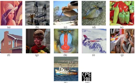
In this paper, we use eleven different color images as the
test images. As shown in Figs. 6 (a-k), they are ‘Lena’,
‘Tower’, ‘Bird’, ‘Fish’, ‘Peppers’, ‘House’, ‘Girl’,
‘Baboon’, ‘Airplane’, ‘Barbara’, and ‘Boat’ - all with
dimensions 256256. In addition, the black and white binary logo ‘CPE 2011’ with size 3232 is synthesized
as a watermark, shown in Fig. 6 (m). In order to evaluate
our proposed method, two criteria are used. They are
“peak-signal-to-noise-ratio (PSNR)” and “normalized
correlation (NC)”. The PSNR is computed to measure the
to measure the quality of the extracted watermark. These
two parameters are defined as follows:
N i M j ij ij y x M N L PSNR 1 1 2 2 10 1 log10 (15)
N i M j N i M j N i M j j i w j i w j i w j i w NC 1 1 2 1 1 2 1 1 ) , ( ˆ ) , ( ) , ( ˆ ) , ( (16)where L is the dynamic range of the pixel intensity;
M
N is the image size; xij and yij are the pixel values
of the original and the watermarked images; and w(i, j)
and wˆ(i, j) are respectively the original and the retrieved watermark. In the following, we compare the performance
of our proposed algorithm based on using the Curvelet
transform for detecting the positions of singularities with
publications [8] and [10]. The procedures of these two
methods and our proposed algorithm are explained briefly
in Table 1.
At first, to compare performance with [8] and [10]
under the same circumstances, we use the well-known
color test image ‘Lena’ with size 256256. The best values for ‘s’ is in the range [0.1 0.5] according to the
tradeoff between robustness and imperceptibility [8]-[11].
So in this work, we also use the same interval values to
obtain ‘s’. The determined EC for all test images based on
using the different threshold values is shown in Fig. 7. In
this paper, we consider the threshold value T=0, then the
EC obtained for all test images is about 1400 pixels. So, a
watermark image with size 32321024 can be
embedded. In addition, two bits are used to save as a
geometrical reference.
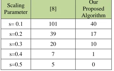
The number of errors for different values for the
scaling parameter ‘s’ for our proposed method and [8], are
given in Table 2. The extracted watermarks are also shown
in Fig. 8. The PSNR and NC of these three methods are
shown in Fig. 9 and Fig. 10. Although the PSNR of our
proposed method is comparable with [8], the achieved NC
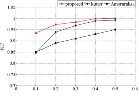
is better than [8] and [10]. Now, we also compare the
performances of these three methods when the Gaussian
weighting mask (see (4)) for averaging the luminance of
an image is used and ‘Lena’ is considered as the host
image. The achieved PSNR and NC based on using a
different variance parameter (2) for the Gaussian mask
are shown in Fig. 11 and Fig. 12. As all the pixels in the
watermarked image are to be changed in [10], and in
addition (5) is not completely satisfied in this method, they
achieved lower values for both PSNR and NC in
comparison with our proposed method.
The watermarked images for Lena, Tower, Bird and
Fish are shown in Fig. 13 where the scaling parameter is
s=0.4 and the variance of Gaussian mask is
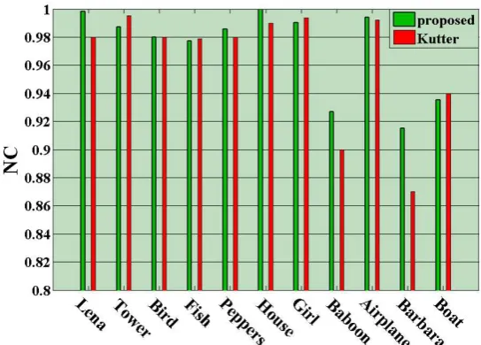
20.5. Wealso compute the NC measure for all eleven images and
compare with [8], and show the results in Fig. 14 where
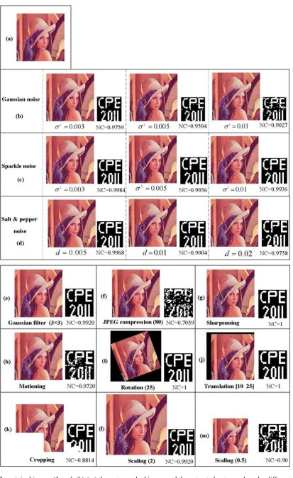
the scaling factor is s=0.4. As regards, the robustness of
our proposed method to geometrical and non-geometrical
attacks, we consider ‘Lena’ and show the watermarked
image and the extracted watermark under different
6. CONCLUSION
An improved retrieval method for watermarking based on
amplitude modulation has been proposed in this paper.
Using the Curvelet transform to detect singularities
prevents embedding the watermark bits at singular points,
lines, and polygons. The experimental results show that by
using our proposed method, the performance of the
watermark retrieval process has been improved in terms of
PSNR and normalized correlation when compared with
two other similar methods.
REFERENCES
[1] I. J. Cox, M. L. Miller, J. L. Bloom, J. Fridrish and T.
Kalker, “Digital watermarking and steganography,”
Elsevier, 2008.
[2] C. I. Podelchuk and E. J. Delp, “Digital
watermarking, algorithm and application,” IEEE
Signal Processing Magazine, vol. 18, no. 4, pp.
33-46, 2001.
[3] M. J. Tsai and H. Y. Hong, “Wavelet transform
based digital watermarking for image
authentication,” International Conference on
Computer and Information Science, 2005.
[4] M.A. Suhail and M.S. Obaidat, “Digital
watermarking-based DCT and JPEG model,” IEEE,
Transactions on Instrumentation and Measurement,
vol.5, pp. 1640-1647, 2003.
[5] C. Deng and X. Gao and X. Li and D. Tao, “A local
Tchebichef moment-based robust image
watermarking,” Elsevier, Signal processing, vol. 89,
pp. 1531-1539, 2009.
[6] Xinbo Gao, Cheng Deng, Xuelong Li, and Dacheng
Tao, “Geometric Distortion Insensitive Image
Watermarking in Affine Covariant Regions,” IEEE
Transaction on Systems, Man, and Cybernetics, vol.
40, no. 3, pp. 278-286, 2010.
[7] F. Ji and D. Huang and C. Deng and Y. Zhang and
W. Miao, “Robust Curvelet-domain watermarking
based on feature matching,” International journal of
computer mathematics, vol. 88, no. 18, pp.
3931-3941, 2011.
[8] M. Kutter and F. Jordan, and F. Bossen, “Digital
signature of color image using amplitude
modulation,” Journal of Electronic Imaging, vol. 7,
pp 336-332, 1998.
[9] R. Puertpan and T Amornraksa, “Gaussian pixel
weighting masks in amplitude modulation of color
image watermarking,” International Symposium on
Signal Processing and It’s Applications, vol. 1,
pp.194-197, 2001.
[10] T. Amornraksa and K. Janathawongwilai, “Enhance
image watermarking based on amplitude
modulation,” Elsevier, Image and computing, vol.
24, pp.111-119, 2006.
[11] Y. Bei, and S. sang, “Color digital watermarking
based on amplitude modulation and SVR,” Journal of
[12] E. Candes and D. Donoho, “Curvelets, a surprisingly
effective non adaptive representation of objects with
edges,” Univ. Press, 2000.
[13] E. Candes and D. Donoho, “Continuous Curvelet
transform I. resolution of the wavefront set,” Appl.
Computer. vol. 19, no. 2, pp.162-197, 2005.
[14] E. Candes and D. Donoho, “Continuous Curvelet
transform II. discretization and frames,” Appl.
Computer, vol. 19, no. 2, pp.162-222, 2005.
[15] E. Candes and L. Demanent and D. Donoho, and
L.Ying, “Fast discrete Curvelet transforms,”
Multiscale Model. Simul, vol. 5, no. 3, pp.863-899,
2006.
[16] Jianwei Ma, “The Curvelet transform,” IEEE Signal
Processing Magazine, vol. 27, no. 2, pp. 118-133,
2010.
[17] S. Nicam and S. Agarwal, “Curvelet-based
fingerprint anti-spoofing,” Elsevier, Signal, Image
and Video Processing, vol. 4, no. 1, pp.75-87, 2010.
[18] J. L. Starck, E. J. Candès, and D. L. Donoho, “The
Curvelet transform for image denoising,” IEEE
Trans. on Image Process., vol. 11, no. 6, pp. 670–
684, 2002.
[19] M. Mansourpour, M. Rajabi,. and J. Blais, “Effects
and performance of speckle noise reduction filters on
active radar and SAR images,” International
Workshop on Photogrammetry and Remote Sencing,
Topographic Mapping from Space, 2006.
[20] Z. Liu and J.Qiu “Study of technique of edge
detection based on Curvelet transform,” International
Symposium on Computational Intelligence and
Design, pp.543-545, 2009.
[21] J. Shen, “Hybrid no-reference natural image quality
assessment of noisy, blurry, JPEG2000, and JPEG
images,” IEEE Trans. on Image Process., vol. 20, pp.
2089–2098, 2011.
[22] Y. Cui, Y. L. Chen, J. Yang and H. F. Rashvand,
“SAR image edge detection using Curvelet transform
and Duda operator,” IEEE Electronic Letters, vol. 46,
i,j
[image:14.595.232.364.251.380.2]Fig. 1: The neighboring pixels around ( ji, ) which are used to predict the original pixel, for c=2 in (2).
Fig. 2: Continuous Curvelet tiling of frequency.
(a) (b)
Fig. 3: The basic digital Curvelet tiling by using, (a) W segmentation and (b) V direction segmentation.
15
50 15 15
50 50 45 15 15
50 50 50
50
[image:14.595.185.414.421.531.2] [image:14.595.229.367.577.702.2](a) The original Image
[image:15.595.81.518.68.264.2]
(b) level 1 (c) level 2 (d) level 3 (e) level 4 (f) level 5 Fig. 5: The reconstructed image by using the inverse Curvelet transform for each scale level.
(a) (b) (c) (d) (e)
(f) (g) (h) (i) (j)
(k) (m)
[image:15.595.58.528.372.660.2]Fig. 7: the computed EC for eleven test images based on different threshold values.
(1) (2) (3) (4) (5)
[image:16.595.186.414.334.424.2]
(6) (7) (8) (9) (10)
Fig. 8: Extracted watermark via different scaling parameters s=[0.1 0.5] from left to right, where ‘Lena’ is used as the host image. The first row belongs to [8] and the second row belongs to our proposed method without using the Gaussian mask.
[image:16.595.185.411.484.646.2]Fig. 10: NCs for different values of the scaling parameter (s) where ‘Lena’ is used as the host image.
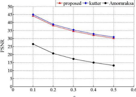
Fig. 11: PSNRs for different variances of the Gaussian mask. The scaling parameter is s=0.2.
[image:17.595.183.415.505.669.2]
(a) (b) (c) (d)
[image:18.595.110.486.70.259.2]
(e) (f) (g) (h)
Fig. 13: Vision comparison between the original images (a, c, e, and g) and the watermarked images (b, d, f, and h) where
s=0.4 and
2=0.5. The computed PSNRs are in order [32.40, 33.75, 29.77, 30.23]. [image:18.595.161.433.337.532.2]Table 1: The procedure of the three watermarking methods.
Method Watermark Embedding
Position Watermark Embedding Procedure Watermark Retrieval
[8] random position using two additional bits cross shape with 8 pixels
[10] all pixels
1. balancing the watermark bits 2. Gaussian pixel weighing mask 3. pixel value replacing
surrounding 8 neighbors
Our Proposed
Algorithm no singularities
1. using Curvelet transform 2. Gaussian pixel weighing mask 3. pixel value replacing
4. using two additional bits
cross shape with 8 pixels (Fig. 1)
Table 2: Number of errors for different values of ‘s’.
Scaling
Parameter [8]
Our Proposed Algorithm
s= 0.1 101 40
s=0.2 39 17
s=0.3 20 10
s=0.4 7 1
[image:20.595.201.397.327.449.2]