RIT Scholar Works
Theses
Thesis/Dissertation Collections
8-1-1983
A constant force bicycle transmission
Thomas Chase
Follow this and additional works at:
http://scholarworks.rit.edu/theses
This Thesis is brought to you for free and open access by the Thesis/Dissertation Collections at RIT Scholar Works. It has been accepted for inclusion
in Theses by an authorized administrator of RIT Scholar Works. For more information, please contact
Recommended Citation
Approved by:
A Thesis Project Submitted
in
Partial Fulfillment
of the
Requirements for the Degree of
MASTER OF SCIENCE
in
Mechanical Engineering
Prof.
Richard Budynas
Thesis Adviser
Prof.
Dr. Bhalchandra V.
Karlekar
Department Head
Prof.
'"egible Signature
Prof.
Ray
C.
Johnson
DEPARTMENT OF MECHANICAL ENGINEERING
ROCHESTER INSTITUTE OF TECHNOLOGY
ROCHESTER, NHJ YORK
ABSTRACT
A
prototype
design
for
ahuman
poweredautomatic
transmission
intended for
useon
an
ordinary
touring
bicycle is
presented.
The
transmission
is
intended to automatically
adjustthe gearing
ofthe
bicycle
to
maintain
an optimum pedalforce,
regardless ofthe
currentriding
conditions.Therefore,
the
transmission
eliminatesthe
needfor the
cyclist
to
manually
adjustthe
bicycle
gearing.The
entiretransmission
is
a self-contained unitdesigned to
bolt
ontothe
rearwheel of an
otherwise
unmodified27-inch bicycle.
The transmission
combines a unique adaptation of acommercially
popular
continuously
variable
traction
drive
with atotally
mechanicalintegral
feedback
controller.The
features
ofthe traction
drive
unique
to
its
application
to
abicycle
are outlinedin
detail,
along
with
an analysis ofthe
important traction
drive design
parameters.The
control systemis
also
uniquely
adaptedto the
requirements ofbicycling.
A detailed
classicalanalysis
of
the
controlleris
presented
to verify its
desirable
performance
characteristics.In
addition,
a
numerical simulation ofthe
transmission
is
included
to
accurately
predictits
performance
undertypical
operating
conditions.
A knowledge
of
typical
pedalforce
profilesfor
normaltouring
cycling
is
prerequisitefor the design
ofthe
constantforce bi
Abstract
i
List
ofSymbols
1
1.
Introduction
7
1.1)
Scope
7
1.2) History
ofthe
Constant Force
Bicycle Transmission
.9
1.3) History
ofthe
Pedal
Data
Instrumentation
12
1.4) Summary
15
2.
Overview
ofthe
Constant Force Bicycle Transmission
...16
2.1)
Introduction
16
2.2) Continuously
Variable Transmission Overview
16
2.3)
Control
System Overview
19
2.4)
Additional
Features
28
3.
Pedal
Data
Instrumentation
31
3.1)
Introduction
31
3.2)
System Overview
\
. .31
3.3)
Pedal
Force Sensor
35
3.4)
Pedal
Position Sensor
48
3.5) Frequency
to
Voltage Converter
53
4.
Design Criteria for the Constant
Force
Bicycle Transmission
60
4.1)
Introduction
60
4.2)
Overview
ofthe Test Data
60
Design Maximum
Pedal
Force.
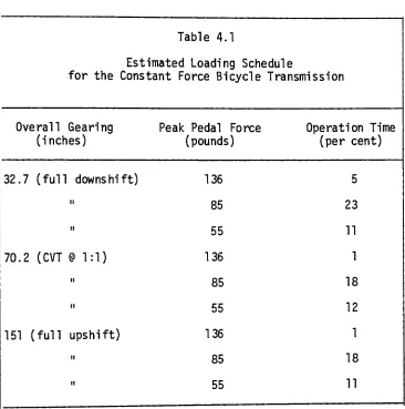
. . .Estimated
Loading
Schedule.
. . .Continuously
Variable Transmission
Introduction
Principle
ofOperation
4.6
4.7
The
5.1
5.2
5.3
5.4)
CVT
Analysis
5.4.1)
Worst-Case Tractive
Force
Requirements
. . .5.4.2)
Derivation
ofthe Traction Ball
Normal
Force
5.4.3)
Traction Fluid
Performance
5.4.4)
Maximum Stress
in
the
CVT
5.4.5)
Transmission Life Estimate
The Constant
Force
Controller
Unique
Characteristics
ofthe
Constant
Force
Bicycle Transmission
CVT
6.1
6.2
6.3
6.4
6.5
6.6
6.7
6.8
Introduction
Principles
ofOperation
Basic
Modelling
ofthe Constant
Force
Controller.
.Shift Torque
Requirements
Modelling
the Control
System
Input
Numerically
Modelling
the Constant Force Controller
Simulation
ofthe Control
System Performance.
. . .Linear Model
ofthe Constant Force
Controller
. . .6.9)
Frequency
Response
Analysis
ofthe
Constant Force Controller
164
7.
Conclusion
173
Acknowledgments
176
Bibliography
177
c- :
Total
chain
reduction
between
the
pedal
crank andthe
input
of
the continuously
variable
transmission
c- :
Total
geardown
between the integrator
driven
wheel,
a, andthe traction
ball
shift
angle,
e
c.
:Leverage
ofthe
floating
traction ball
lever
f
:Frequency
ofthe
sinusoidal
input force
from the
pedal crank(hz)
F
:A
generalforce
(lb)
f
:Corner
frequency
ofthe
constantforce
controller(hz)
Fp
:Force in the
chain
driving
the
input
sprocket ofthe
continuously
variable
transmission
(lb)
FCR
:Normal
force
of atraction ball
against
a cradlebearing
ofthe continuously
variabletransmission
(lb)
FD
:Peak
value
ofthe ideal
pedalforce
(lb)
F.
:Normal
force
between the integrator
driving
disc
andthe
integrator
driven
wheel(lb)
FN
:Normal
force
of atraction
ball
againstthe
input
oroutput
disc
of
the
continuously
variabletransmission
(lb)
Fp
:Pedal
force
(lb)
-1-fpp
:Output
frequency
ofthe
pedal
position sensorinstrumen
tation
(hz)
Fg
:Sum
ofthe
forces
in the two
springs
ofthe
chainforce
sensor
linkage
(lb)
F__t
:Force in
the
equivalent
spring
(with
spring
constant
k
)
of
the
force
sensor
linkage
whenthe
force
sensorlinkage
displacement,
y,
is
zero(lb)
F-.R
:Tractive
(frictional)
force between the traction ball
andthe
input
or output
disc
ofthe continuously
variable
transmission
(lb)
F,,
:Total
wedging force
of atraction ball
into
the
input
andoutput
discs
ofthe continuously
variabletransmission
(measured
in the
plane parallelto the
input
andoutput
discs)
(lb)
G
:Transfer function
ofthe
constantforce
controllerK
:Gain
ofthe
constantforce
controllerk
. :Actual
spring
constant of each ofthe two
parallel
chainact
force
sensorlinkage
springs(lb/in.)
k
:Equivalent
spring
constant ofthe two
parallel
chaineq
force
sensorlinkage
springsacting through the
chainforce
sensorlinkage
(lb/in.)
M.A.
:Mechanical
advantage ofthe
chainforce
sensorlinkage
ri
:Radius
of
the
integrator driven
wheel(in.)
r-jn
:Radius
from the
axis
ofrotation
of
the traction ball
to
the
point
ofcontact
withthe
input disc
(in.)
rout
:Radius from
the
axis of rotation ofthe traction ball to
the
point
ofcontact
withthe
output
disc
(in.)
rpc
:Length
ofthe
pedal crank(in.)
rSCVT
:Pitch
radius ofthe
input
sprocket
ofthe
continuously
variable
transmission
(in.)
s :
A
complex
numbert
:Time
(sec)
T
:Period
ofthe
pedal crank rotation(sec)
T
:Time
constant
ofthe
constantforce
controller(sec)
TDW
:Torque developed
by
the
integrator
driven
wheel(lb-in.)
T.
:Input torque to the continuously
variabletransmission
(lb-in.)
T-_v
:Constant
torque
valuefor T
Tout
:Output
torque
from the continuously
variable
transmission
(lb-in.)
Tref
:Function
describing
the
peak
value
ofthe
sinusoidal
torque
required
to
drive
the
rear wheel ofthe
bicycle
(lb-in.)
TRW
:Torque
required
to
drive
the
rear wheel ofthe
bicycle
(lb-in.)
Tshl.ft
:Torque
requiredto
change
the
shiftangle
of atraction
ball
ofthe continuously
variable
transmission
(lb-in.)
T"w
:Input
torque to
a worm gear ofthe continuously
variabletransmission
(lb-in.)
Tw
. :Output
torque from
a worm gear ofthe continuously
variable
transmission
(lb-in.)
Too/
I,----2%
responsetime
of
the linear
model ofthe
constantforce
.c/d, ii nearcontroller
to
atrue step
input
(sec)
x :
Input function
to
the linear
model ofthe
constantforce
controller(lb)
X
:Magnitude
ofthe
sinusoidalinput
function to the linear
modelof
the
constantforce
controller(lb)
y
:Chain
force
sensorlinkage
displacement; i.e.,
the
relativedisplacement between the
center ofthe integrator
driving
disc
andthe
center!ine
of
the integrator driven
wheely
:Angular
displacement
ofthe
right
pedal
crankfrom
top
dead
center(rad)
n :
Efficiency
ofthe
worm gears ofthe continuously
variabletransmission
e
:Shift
angle
ofthe continuously
variabletransmission
(rad, deg)
ecc
:Steady
state
shift angle ofthe continuously
variabletransmission
(deg)
3SS
y. :
Coefficient
offriction between the integrator
driving
disc
andthe integrator driven
wheelu :
Maximum
assumed value ofthe
coefficient offriction
ofnriax
the
traction
fluid
ofthe continuously
variabletransmis
sionu . :
Minimum
permissible coefficient offriction
ofthe
traction
mmfluid
ofthe
continuously
variabletransmission
a :
Compressive
stress(lb/in.2)
fc>c
:Corner
frequency
ofthe
constant
force
controller
(rad/sec)
-i :
Angular velocity
ofthe
integrator
driving
disc
(rad/sec)
pedal
:An9ular velocity
ofthe
pedal
crank
(rad/sec)
is
presented
here.
The
constant
force
transmission
is
ahuman
powered
automatic
transmission intended for
use
on anordinary 27
inch
touring
bicycle.
The transmission is designed
to
automatical
ly
adjust
the
bicycle
gearing to
maintainthe
pedalforce
at
arider-prescribed
level
underall
riding
conditions(assuming
this
is
possible
withinthe gearing
limits
ofthe
transmission).
Thus,
the transmission
eliminatesthe
needfor the
cyclist
to manually
adjust
the
bicycle
gearing,
ason
anordinary
10-speed,
making
it
simpler
for the
riderto
maintain an optimal power output at alltimes.
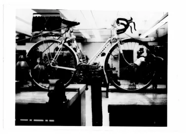
The
transmission
is
a self-contained combination of a continuously
variable speeddrive
and control system(Figure
1.1).
The
unitis
intended to
bolt
onthe
rear wheel shaft of an otherwise unmodified
bicycle
frame;
it
replacesthe
standard10-speed
derailleur.
The
transmission
is
driven
by
the
chain of a standardfront
pedal crank.The
unit requires no external power.A
completedescription
of
the
prototypedesign
and ananalysis
of
its
mechanicalintegrity
and predicted performanceis
presented
here.
The
prototypehas
notbeen
constructed atthe
time
of
this
writing;
however,
the
analysis presentedhere
fully
justifies
its
actual construction.All
partsin the
transmission
-7-Ul I/) r-E in a ta
s-oj
o >
<u o s_ o
in c o o
ai
dimensions.
The
actual
prototype
transmission
willhave
three
undesirable
characteristics:
it
will
be
large,
heavy,
andexpensive.
However,
the
prototype
has
been
"overdesigned"to
help
insure
its
properinitial
operation.
For
example,
the
control systemhas been de
signed
to
produce
the
maximum powerthat the
variable
ratiodrive
could
reasonably
require while
shifting
(see
Chapter
6),
and allshafts
subjected
to
fatigue
loading
have
been designed for
infinite
life
at
the
maximum expectedinput
load.
Therefore,
if the
prototype
performance
is
encouraging,
optimization
ofthe
design
willsubstantially
reduce
its
size,
cost,
and weight.A
suitably
optimized
design
wouldbe intended
for marketing
as abolt-on
substi-tute
for derailleur
gearing
on anordinary 10-speed
touring
frame.
2) History
of
the
Constant Force Bicycle
Transmission
Widespread
interest in
alternatives
to the
conventionalderailleur
and multispeedhub
gearsfor
useas
bicycle
transmis
sions
has
existedfor many
years(reference
21).
However,
only
afew
attempts
at
atransmission that automatically
adjuststhe
gearing
to
maintain optimal powerinput from the
riderhave been
r^
rj\>_1*1
\
I
tic
i
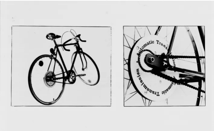
Figure
1.2)
The BTCA Automatic Bicycle Transmission
(Photos
extractedfrom Reference
5)
The only
automatic
transmission known to have actually been
marketed
is
the BTCA drive
(reference
5)
.This
transmission
is
also
the
most
similar of earlier attemptsto the
constantforce
bicycle transmission;
it
combines acontinuously
variabletrans
mission
witha
mechanical control system.However,
both
ofthese
elementsare
^ery different
from
their
counterpartsin
the
constantforce
bicycle
transmission.
The continuously
variabletransmission
of
the
BTCA drive is
an
unusualgeometry
consisting
of aplanetary
gear-like system with
incrementally-driven
planets.The
planets1
The only information
availableto the
author onthis transmis
sionis
anadvertising brochure from its
developer,
the
Bicycle
Technology
Corporation
ofAmerica
(reference
5).
All
observations
madehere
arebased
on
that brochure.
The
commercial [image:17.517.73.428.109.327.2]control
device" and a"centrifical
anticipatory
control".
The
principle
ofoperation
ofthe
controller
is
not
clear;
it
appears
to
be
aproportional
systembased
on
the
speed
ofthe
chain
and
the
rear wheel.The
unit
is housed
in
a
custom rear wheelhub.
The
transmission
andbicycle frame
are
apparently
soldonly
as anintegral
unit.A
secondattempt
at
an
automatic
transmission
combines
aproportional
force-sensitive
controller on avariable
ratiofront
sprocket
(reference
15).
The
variable
sprocket
itself
is
a16-step
version
of aHagen-type
geometry
(reference 23)
.Proportional
force
controlis
obtainedby
spring-loading the
variable
pitchelements
ofthe
sprocket.
Several
attempts
have
been
made at
hydraulic
bicycle trans
missions.
The typical
configurationconsists
of a pedal-poweredhydraulic
pump
driving
ahydraulic
motoron
the
rear wheel(refer
ences
4
and25);
reference
(4)
mentionsthe possibility
ofinclud
ing
automatic shiftfeatures.
Another design
(reference
19)
utilizes a
hydraulic pump
attachedto
the ring
gear of aplanetary
gear
set
to
vary
the bicycle
shift
ratio.
The practicality
ofsuch systems
is
questionablebecause
ofthe low
efficienciesassociated
withhydraulics
(on
the
order of80%
atbest);
the
efficiency
of abicycle
transmission
must
exceed90%
to
be
competitive
with
conventional
positive
drives
(reference
21).
Several
other
unusual
bicycle transmissions have been
proposed.
Most
attempt
to
modify
the
standard
circularpedal
crank
cycle.
A
representative
summary
is
provided
in
reference
(11).
Outside
of
those
already
mentioned,
none
address
the
problem
ofautomati
cally
adjusting
the
gearing.
The
constant
force bicycle
transmission
is
uniquefrom
allother
automatic
bicycle
transmissions
in
providing integral
control
ofthe
pedalforce.
The
advantages
ofthis
approach
willbe
clarified
in
Chapter 2.
The
high-efficiency
traction
drive
utilized in
the
design
has
also neverpreviously been successfully
adapted
to
abicycle.
1.
3) History
of
the Pedal
Data
Instrumentation
Knowledge
oftypical
pedalforce
profiles,
describing
the
input
to the
constantforce bicycle
transmission,
is
prerequisiteto
designing
the transmission.
Specifically,
the
pedal crankspeed,
the
generalshape
ofthe
pedalforce
input,
the ideal
pedalforce
(i.e.,
the
pedal
force
the
constant
force
transmission
willattempt
to
maintain),
andthe
design
maximum pedalforce
expectedfrom
average
cyclists whenriding
a
modernlightweight
touring
bicycle
under normalconditions
arerequired.
Little
ofthis
nomic
data concerning
bicycling
has
been
published;
the
content
of
these
studies
is
briefly
summarized
here.
An
early
study
ofthe
force
exertedon
abicycle
pedal
underactual
riding
conditions
is
described
in
reference
(16).
A
mechanical
(clockwork-driven)
recorder
was attachedto
aspring-loaded
pedal
of an "ordinary"bicycle.
The
data
is
interesting
in
that
it
shares
the
approximately
sinusoidal
pedal
force
profile
determined in
Chapter
4; however,
the
appliedforces differ
sub
stantially from
that
appliedto
a modern10-speed frame.
Additional
data concerning
average
cyclists under normaltouring
conditionsis
extremely
limited.
Reference
(1)
addressesthis
problem;
however,
the
pedal
force is
not measured.Instead,
the
poweroutput
ofthe
rideris
estimatedby
measuring the
oxygenconsumption of
the
rider.Reference
(7)
utilizes a similartech
nique
to
evaluatethe
effect oftire
size
onbicycling
efficiency.Reference
(22)
comparesthe
oxygen consumptiontechnique
ofthe
previous
references with power estimatesbased
on aknowledge
of
the
expectedtractive resistances;
once
again,
the
pedalforce
is
not examined.
Reference
(21)
presents aninteresting
summary
ofseveral similar ergonomic
studies
of
bicycling,
emphasizing
the
Three
additional
references examinethe
actual
pedalforce
exerted
by
acyclist;
however,
none ofthese
studies
have been
conducted under "average"
conditions.
Reference
(18)
measures
the
pedal
force
exertedby
racing
cyclists
atstart-up,
in
addition to examining the
output
ofracing
cyclists
withstationary
dynamometer
andphotographic
studies.
Reference
(6)
studies
pedalling efficiency
withan
instrumented
pedal
on
astationary
dynamometer.
The
data
from
these
studies
are
again usefulonly
in
validating the
assumption
of aroughly
sinusoidal pedalforce
profile
estimatedin Chapter 4.
Reference
(12)
presents a plotof maximum crank
moment
measured as afunction
of crank angleunder static conditions only.
The
pedalling
studies presentedin Chapters 3
and4
areunique
in examining the pedalling habits
ofaverage
cyclistsunder actual road conditions.
The
peaklevels
ofthe
pedalforce
were
found to differ vastly from the "maximum
possible power output"
nature of
the
previoustests.
The
estimate of an "ideal"pedalling
force is
also unique.The data
was collectedusing
the
samebicycle
frame
to
whichthe
prototype constantforce
transmission
is
fitted,
andthe data
was generated underriding
conditions
closely
resembling the
conditionsto
whichthe
prototype
transmission
willbe
subjected.Therefore,
eventhough
the
4) Summary
All
important information
underlying the
design
ofthe
prototype constant
force bicycle
transmission
is
presentedhere.
Chapter
2
presents
ageneral
description
ofthe
prototype
transmis
sion
andits
operating
characteristics.Chapter 3 describes the
instrumentation
package
usedto
determine
the typical
input
to the
transmission.
Chapter 4
summarizesthe data
collected withthe
instrumentation
package
described
in
Chapter 3
and reducesthese
data
to
a set ofdesign
criteria.Chapter 5
presents adescription
and an analysis of
the continuously
variable
traction
drive
usedto
vary the gearing
in
the
transmission.
Chapter 6
presents ade
tailed
analysis
ofthe
constant
force
controller and predictsthe
response of
the transmission
to
a set oftypical
inputs.
An Appen
dix lists
the
computer program usedto
simulatethe
performance2.
Overview
ofthe Constant Force Bicycle Transmission
2.
1)
Introduction
The
constant
force bicycle
transmission
is
a uniqueadaptation
of a popular commercialcontinuously
variable
traction
drive
combinedwith
atotally
mechanicalfeedback
control system.The front assembly
drawing
ofthe
complete
transmission
is
shown
in Figure
2.1.
The
entire self-contained systemis designed to
bolt
on
the
rear wheelshaft
of a standard10-speed bicycle.
The
prototype
is
fitted to the
popularPeugeot UO-8 10-speed
touring
frame.
This
chapter provides a generaldescription
ofthe
two
main
components ofthe
transmission
and concludes with asummary
of
the
generaldesign features.
2.
2) Continuously
Variable Transmission Overview
The
gear ratio ofthe
constantforce
bicycle
transmission
is
set via a
continuously
variabletransmission,
orCVT.
The CVT is
a
"traction
drive"; i.e.,
it
transmits
powerthrough frictional
contact
between
smooth steel surfaces.Utilizing
aCVT
enablesstepless
shifting
over a wide speedrange,
whichis
particularly
well suited
for
coupling
with a control system.The
constantforce bicycle
transmission
CVT
sharesthe
basic
principle of operation of
the
commercially
popularCleveland
1
Peugeot
is
abrand
name;
UO-8
is
a model number.-16-c o
c o in m r
to c
s-o >>
CD O S-o
c re
+->
to c o o OJ
o
3: 10 S-Q
OJ to (0
2
Speed
Variator.
The
transmission has
ageometry
similar
to
alarge ball
bearing.
Shifting
is
accomplished
by
varying the
angle
ofthe
axis
ofrotation
ofthree
"traction
balls"between
input
andoutput
discs
(see
Chapter 5).
The
axis
ofrotation
ofeach
traction ball
is
positioned
by
a worm gear.The three
wormgear
shafts
are
coupled
with a roller chain(the
lower
chain
visible in Figure 2.1).
The
upperright
wormshaft
is
equipped witha second
sprocket,
whichis driven
by
the
control system.Bicycle
gearing
is
expressed asthe diameter
ofthe
equivalent
driving
wheel;
i.e.,
gearratio
times the diameter
ofthe
driving
wheel.Stock Peugeot UO-8 derailleur gearing
variesfrom
a
low
gear of38.6 inches
(1.43:1
sprocket
ratio)
to
ahigh
gearof
100 inches
(3.71:1
sprocketratio)
in
10 finite
steps.The
constant
force
bicycle transmission
provides
continuousgearing
from 32.7 inches
(1.21:1
equivalentsprocket
ratio)
through
ahigh
gear of151
inches
(5.58:1
equivalent sprocket ratio).Therefore,
simply
replacing the derailleur
withthe
uncontrolled3
CVT
wouldin
itself
be
desirable.
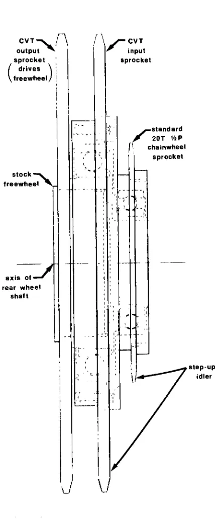
The
chain speedstep-up
atthe
input
to the CVT
andthe
step-down
at
the
outputare
necessary
to
reducethe
stressesin
the CVT to
an
operablelevel.
The
entire step-up/step-downManufactured
by:
Eaton
Yale
andTowne,
Inc.
Cleveland Worm
andGear
Division
3262 East 80th Street
Cleveland,
Ohio
44104
3
rides
over
the
freewheel
viatwo
ball
bearings.
The leftmost
step-down
sprocket
drives
the
freewheel
directly,
as
in
an
ordi
nary
bicycle
transmission.
The
CVT
is lubricated
with
"traction
fluid",
asynthetic
lubricant
combining
arelatively
high
coefficient
offriction
with
good
anti-wear
characteristics.
A
sealed
plexiglass
caseis
provided
aroundthe
critical
CVT
components
to
keep
the trac
tion
fluid in
andcontaminants
out.Plexiglass
provides
alight
weight,
durable
case
that
allows
visualinspection
ofthe CVT
components.
The
rotary
seals
onthe
case
are
all standard0-rings;
the sliding
seals
are
packedfelt;
the
coverplate
sealsare
corkcomposition
gasket
material.2.
3)
Control
System
Overview
The
transmission
control systemis
devised to
produce
aconstant
average
force
at
the
pedals
regardless
of
riding
conditions.
The
controlleris
totally
mechanical,
eliminating the
needfor
externalelectric,
hydraulic,
orpneumatic
power.The
The freewheel
is the base
of
the
stockSimplex
(trade
name)
10-speed
rear chainwheel cluster.5
Sun Oil
Company
^standard Jf 20T V2P
chainwheel sprocket
J
\J
[image:27.517.153.367.97.613.2]controller consists
of achain
force
sensor,
amechanical
integrator,
agear-down
to the
traction
ball
wormgears,
and
a setof
manual
controls
(see
Figure
2.1).
The
chain
force
sensor
consists
of afloating
sprocket carried
by
aRoberts-type
straight
line
mechanism
(see Figure 2.3).
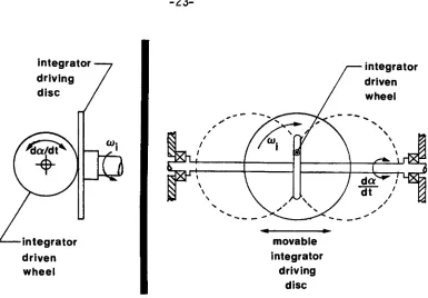
The
mechanical
integrator
is
comprised
of afloating
integrator
driving
disc,
carriedby
the
chain
force
sensor
linkage
andpowered
by
the
floating
sprocket,
and a
fixed integrator driven
wheel(see
Figure 2.4).
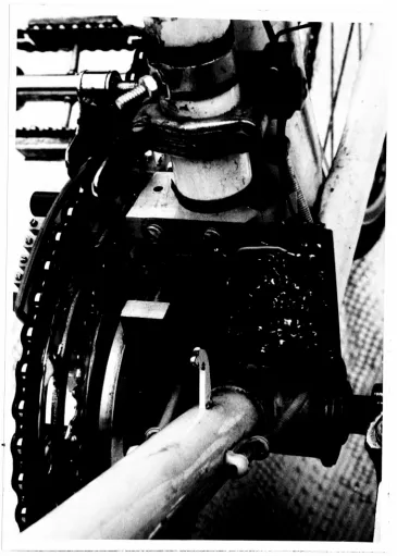
The
gear-down
system,
in
addition
to the
wormgears
themselves,
consists
of a
1:4
bevel
gear
set and a15:36
chainreduction
to the
worm gearshafts
(see
Figure
2.5).
Manual
controlsare
providedfor
adjusting the
desired
pedalforce,
shutting
offthe
automatic
control
system,
andadjusting the transmission
shift
ratio
(assum
ing
the
automatic
systemis disabled).
Thus,
total
manual controlof
the
CVT is
available.
The
nominalpeak
value
ofthe desired
pedal
force is
approximately 35
pounds
(see
Chapter
4);
it
may be
set
between 25-65
pounds.Ergonomic
data indicate
that
bicyclists
mostoptimally
produce
constant powerat
a
constant rate ofpedalling
of about60 RPM.
Since
poweris
the
product offorce
times
speed,
this
is
equivalentto
inputting
a constant pedalforce
at a constantc
Various
"optimal"Ol
d) CJ3 fO
__
S-o
to cz (D CO CD
O
S-o
o
w
TJ O
CZ
"r-(0
__
C_3 CD x: 4->
4-O
C7)
s
CO
S-Q
J_
E
0) to to
Csj
OJ
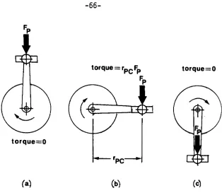
(l):
JO
-integrator
driven
wheel
movable
integrator
driving
disc
Figure
2.4)
Basic Mechanical
Integrator Geometry.
pedal crank
rotational
speed.Therefore,
acontrol
systemthat
will
adjust
the
bicycle gearing to
maintain
either aconstant
pedal
force
or a constant pedal crankrotational
speed will probably
maintain
optimal
gearing.It
has been
assumedhere
that the
pedal
force
is
a moredependable
indicator
ofimproper gearing than
pedal crank rotational
speed.Therefore,
the
input
chainforce,
whichis
equivalent
to the
component ofthe total
pedalforce
being
transmitted
to the
rearwheel,
is
measuredin the
constantforce
bicycle
transmission.
The
rideris
assumedto
be
ableto
maintainthe
[image:30.517.67.452.79.347.2]01 to to a:
cD CD
CZ CD >
Q
S-o +-> CO s-D1 *D -I-) C
cu
cz I
3: CO S-Q
-_
=
a> in to <:
CM
CD
have been
ofthe
proportional
type,
as
reviewed
in
Chapter
1.
The
use
ofintegral
control
produces
two
majoradvantages
over
propor
tional
control.
First,
an
integral
controllerproduces
zero
steady-state
errorto
astep
input,
while
aproportional
control
ler
will
have
finite
steady-state
error,
oroffset.
Second,
the
integral
controller
acts
as alow-pass
filter,
reducing
effectsof
high
frequency
input
to the
control
system.The
physical
significance
of
zerosteady-state
erroris
wellillustrated
by
envisioning the behavior
ofbicycles
equipped withthe two types
of controlsystems
whileriding the
bicycles
up
ahill.
In
orderfor the
bicycle
withthe
proportional controllerto
remain
downshifted,
the
force
on
the
pedalmust
remaintoo
high.
In
contrast,
the integral
controller willdetect
the high
pedal
force,
downshift
the transmission
untilthe ideal
pedalforce is
resumed,
andthen
leave
the
transmission
in
the down
shifted
state
until anotherdeviation from the ideal
pedalforce
is
detected.
In
simplerterms,
the
rider ofthe bicycle
withthe
proportional controller will
have
to
pedaltoo
hard
allthe way
up the
hill,
whilethe
rider ofthe bicycle
withintegral
control will
be
ableto
pedal atthe ideal
force
for
most ofthe
hill.
The initial
time
requiredto
reachthe
ideal
pedalforce
on
the
integral
control system afterstarting up the hill
is
The low-pass
filtering
effect
ofintegral
control
is
important
because the
control systeminput,
the
component
ofpedal
force
transmitted to the
rearwheel,
varies
approximately
sinusoidally
at
afrequency
oftwice the
pedal
crankrotation
rate
(see
Chapter 4).
A
straight
proportional
controller
willconstantly
change
the
shift
ratio
at
this
same
rate.
This
effect
is
greatly
reduced
by
the
integral
controller;
the
shift
ratio
willchange
very
little
overone
pedal
cycle
(assuming
the
pedal
force is
nominally
at
the
ideal
level).
The
2%
response
time
ofthe
integral
controllerto
a pedalcrank speed of
60 RPM is roughly 8.5
seconds(see
Chapter 6).
Although
this time may
appearlarge,
it may in
fact
be
desirable.
This
is
best
clarifiedby
a second physical example.Assume
the
bicycle
riderapproaches
a
traffic
signal whichappears
to
be
changing
red.
The
rider will wantto apply
astrong
"kick"to
the
pedals
for
a
few
cyclesin
orderto
acceleratethrough
the
intersection
rapidly.The low-pass
filtering
effect ofthe
controller,
determined
by
its
relatively high
responsetime,
willpermit
such short-termhigh-power
inputs;
the
controller willre
spond
only to longer
term
trends
in
the riding
conditions.Ergo-nomic studies
in fact
indicate
that
the human
body
is particularly
This
filtering
effect enabled a significantimprovement
over anearly
design
ofthe transmission that included
a mechanical compensatorfor the
sinusoidal
input.
Elimination
ofthe
mechanically
complex compensatorhad little
adverse effecton
testing
the
transmission.
The
Robert's-type
straight
line
mechanism
usedin
the
chainforce
sensor
(Figure
2.3)
is
asymmetrical
4-bar
linkage
which
generates
straight-line
motion
using
allpin
joints.
The
mechanism
generates
anear-perfect
straight
line;
disregarding
clearances
in
the
joints,
the
actual
path
ofthe
integrator
driving
disc
andfloating
sprocket
differs from
aperfect
horizontal
straight
line
by
less
than 0.008
inches
overthe total
range
ofmotion.
Varying
the
position where
the
chainforce
sensing spring
attaches
to the
linkage
varies
the
mechanicaladvantage
between
the
floating
sprocket
andthe
spring.This
enabled "tuning"the
spring
force
to
match
both the
control
system andtraction
drive
requirements
while
designing
the transmission.
As
mentionedearlier,
a
standard
derailleur
freewheel
couples
the transmission to the
rear wheel.This
enablesordinary
back-pedalling
on
the bicycle.
In
addition,
back-pedalling
willdownshift
the
transmission
atthe
maximumpossible
rate.There
fore,
the
transmission
gearing
canbe
fully
reducedin the
"dead
start"
situation
without
accessing the
manual controlknob.
o
2.
4)
Additional
Features
Several
additionaldesign features
areincluded in the
constant
force
bicycle transmission to
enable
low-cost
manufac
ture,
dependable
operation,
andsimple modification.
Specifical
ly,
these features
include bolt-on
design,
straightforward
component
design,
all
pinnedmoving
joints,
and modularfunctional
entities.As
mentioned earlierin
this
chapter,
the transmission
assembly
is
designed to bolt
onthe
rear wheel shaft of a con ventional10-speed
touring
bicycle.
No
modifications ofthe
frame
are
required,
andthe
standard pedal crank and rear wheelare
used.The
entiretransmission
is
cantileveredto
the
chainside
ofthe bicycle
(see
Figure 2.6).
The
width ofthe
basic CVT
(not
including
the input/output
chain extensions andintegrator
driven
wheelassembly)
is only 2-7/8 inches.
The
entiretransmission
is
designed
for
ease of manufacture.Stock
bearings,
gears,
sprockets,
seals,
springs,
andfasteners
have
been
used wherever possible.The only
non-stock partsre
quiring
grinding
in
the
transmission
arethe CVT input/output
discs
and cradlebearing
rings(see
Chapter 5).
All
remaining
components are
easily
fabricated
on a standard enginelathe
and vertical mill.All
movablejoints
in the
entiretransmission
are pinjoints.
No
slider,
cam,
or screwjoints
are utilized(discount
OJ ro S-cD
r
(J >* o
CO CD
__ 4->
CZ o
cz o
to
to
I
B to c ro S-QJ O s-o
cz ro O O
(D
__ +->
O
i -M i
or
dirt
contamination andreduces
manufacturing
costs.The
chainforce
sensorlinkage
andintegrator
driven
wheelassembly
are
both
free-standing
modules
that
bolt to the basic
CVT.
This
enablesthe
control systemto
be
modifiedextensively
As described
in
Chapters
2
and4,
designing
the
constant
force
bicycle
transmission
requires
a
knowledge
oftypical
pedal
force
profiles
expected
ona
bicycle
under actualriding
conditions.
Information
concerning the important
parametershas
notbeen previously
published.
This
chapterdescribes
aninstrumenta
tion
package
constructedexclusively to
obtainthese
data.
The
output
generatedby
the instrumentation described
in
this
chapteris
presented and analyzedin Chapter 4.
The total
instrumentation
package consists ofthree
stock andthree
custom-built parts.The
stock partsare
a standard10-speed
bicycle,
a portable stereo audio cassetterecorder,
anda
2-channel
DC strip
chart recorder.The
custom-built parts are a pedalforce
sensor,
a pedal positionsensor,
anda
pair offrequency
to
voltageconverters.
The
operation ofthe
entire systemis
described in
Section 3.2.
Each
ofthe
three
custom parts aredescribed in de
tail
in
Sections
3.3
-3.5.
3.
2)
System Overview
The
instrumentation
packagedescribed
here
records anddis
plays
the
pedalforce
andpedal position of a standard10-speed
bicycle
as afunction
oftime
under actualriding
conditions.-31-The
recording
anddisplay
systems
have been broken into
two
completely independent
sub-systems.
This
enables
the
recording
system
to
be
self-contained
on
the
bicycle
itself;
it
needs
noexternal
connections
ofany kind
anddoes
not
interfere
with
normal
cycling in any
way.
The
second
sub-system
is stationary;
it
converts
data
collected with
the
portable
recording
package
to
a convenient
strip
chart
recorder
display.
The
complete
recording
package
is
shownin Figure 3.1.
The
package
consists
ofa
standard
Peugeot UO-8 10-speed bicycle
equipped
with acustom-built
pedal
crank.The
crankcontains
apedal
force
sensor,
described in Section
3.3,
and apedal
position
sensor,
described in
Section 3.4.
The
custom
pedal
crankis
con
tained
withinthe
same
planar
areaas
astandard
pedal
crank(see
Figure
3.4);
it does
not
interfere
with normaloperation
of
the
pedals
or
the
stock
derailleur.
Both the
pedalforce
andpedal
position
sensors
output a
frequency-modulated
signalin the
audiorange.
The
two
simultaneoussignals
are recorded on separatechannels
of a
standard portablestereo
audio
cassettetape
recorder.
The tape
recorderis
strappedto
a rear wheel carrieron
the
bicycle,
as
shownin
Figure 3.1.
The instrumentation does
notnoticeably
affectthe
"feel" ofthe bicycle.
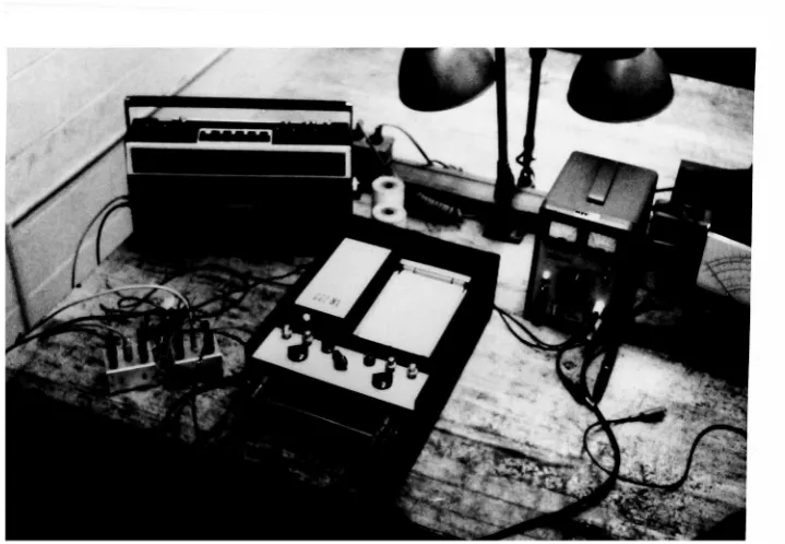
The
display
systemis
shownin
operationin
Figure 3.2.
The
two
channels of an audio cassettetape
recorded onthe bicycle
areplayed
back
through
two
custom-builtfrequency
to
voltage convertE
OJ
4-> to
>>
oo
01 c
r
T3 U o o <D
O-<D
<+-O
s-o.
CO
"O OJ
D-cd
Figure
3.2)
Pedal
Profile
Display
Package.
on
the tape to
a
form
suitable
for
recording
on astock
2-channel
strip
chart
recorder.
Note
that
introducing
the
intermediate
audio
recording
between
the
pedal
crank
sensorand
the strip
chart
recorder
is
not
absolutely
necessary;
the
sensor
could
be
designed
to
record
directly
on
a
portable
strip
chartrecorder.
However,
using the
intermedi
ate
audio
recording
leads
to
severalimportant
advantages.
First,
the
audio
recorderis
muchlighter
in
weight
than
a
strip
chart
recorder.
Second,
the
audio
recorderis
an order ofmagnitude
less
expensive and moredurable
than
astrip
chartrecorder;
there
fore,
it is
muchless
susceptible
to costly damage
when strappedto
[image:41.517.101.461.85.334.2]output; this
effect
is
reduced
using
audio
tape1.
Fifth,
the
audio
cassette
format
ofthe
output
provides
aclean
and
compact
means
ofstoring large
amounts
ofdata;
the
output
canthen be
selectively
converted
to the
(cumbersome)
strip
chart
format in
the
lab.
Finally,
as
will
be
seen
in the
following
section, the
audio
frequency
AC
output
ofthe
force
sensor
also provides
a convenient means
oftransferring
the
signal
from the
rotating
sprocket
to the
stationary frame
without
slip
rings.
3)
Pedal
Force Sensor
The
pedal
force
sensor
detects
the
component
ofthe
pedal
force
whichis
transmitted to the
pedal
sprocket
andchain.
The
sensor
outputs
a
sinusoidal
signal
in the
audio
frequency
range
(500
-1000
hz);
the
output
frequency
is
proportional
to the
pedalforce.
The
entire
self-contained
unitmounts
to the
front de
railleur
sprocket
ofthe
Peugeot UO-8 10-speed bicycle
(see
Inspection
ofthe strip
chart recorderdisplays
ofFigure
4.1
reveal
identical
noise signals superimposed onboth the
pedal position andforce
traces.
This
was causedby
the
physicaljarring
ofthe
audiotape
recorder under actualriding
conditions,
which causedfluctuations
in the tape
speed.Neverthe
less,
the
noiseis probably substantially less
than
that
whichFigure
3.3).
The
unitis entirely
contained
in the
plane
ofthe
pedal
crank
sothat
it
will
not
interfere
withnormal
cycling
in
any way
(see Figure
3.4).
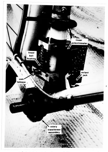
The
signal
is transferred from
the
ro
tating
sprocket
to the
frame
(and
cassette
recorder) through
arotary
transformer
(see
Figures
3.10
and
3.11).
Earlier
attempts
at
determining
the
pedal
force
underdynamic
conditions
(references
6
and
18)
measure
normal
and shearforces
applied
to the pedal,
which
are
both
composed
oftwo
components.
The first
component
is
transferred to the
sprocket
andchain;
this
component
actually
does
workin
driving
the
rearwheel.
The
second
component
is simply
supported
by
the
bicycle
frame;
it does
no useful work.The only
componentof
interest
in
designing
the
constant
force
transmission
is the
component
actually
reaching the
transmission;
i.e.,
the
component
driving
the
pedal
2
crank sprocket and chain .
Therefore,
the
pedalforce
sensoris
designed to
measurethis
component exclusively.The
component ofinterest
is
detected
by decoupling
the
pedalcrank and
the
sprocket andinstrumenting
a
specially-designedlink
between
them.
The
pedal crank sprocket ofa
standard10-speed
bicycle is
typically
bolted
directly
to the
rightpedal
crank.In
contrast,
the
pedal crank sprocket ofthe
pedalforce
sensoris
mounted
to
a
fiberglass
platefastened to the
pedal
crankshaft,
2
s-o to c (D
(V) CD
O i-o
ro
-o 03
ro
0>
Pimirp
^
4}
Pedal
Force
Sensor.
End View.
Fngure
3.4)
bearing,
andthe
in
ner
race
ofthis
bearing
is in
turn
fastened
to the
shaft.
The
bearing
supplies
planar
rigidity
to the
sprocket while
rotationally
decoupling
it from
the
pedal
crank.
Therefore,
if
the
right
pedal
were
replaced
in
Figure
3.5,
the
pedals
wouldspin
freely
without
imparting
any torque to the
front
sprocket
(obviously,
the
bicycle
cannot
be
driven in
this
condition).
The
pedal
crank
and
the
pedal
crank
sprocket
are
linked
witha
specially-designed
right
pedal
crank
arm(Figure
3.3).
The
special
crank
arm
is
equipped with
a
2.25 inch
extension
beyond
the
center ofthe
pedal
crank
shaft.
This
is
coupled
to
ablock
bolted rigidly to the
fiberglass
plate
(carrying
the sprocket)
through
a universaljoint-type
linkage3(Figure
3.6).
Therefore,
any
force
whichis transferred
from
the
pedal
crank
shaft
to the
sprocket must
be transmitted through the
rightcrank
extension.
Figure
3.6
reveals
that the
right
crank
extension
acts
as
a cantilever
beam.
A
signal
proportional
to the
component
ofthe
force
The
universaljoint-like link is
necessary to
obtain
purely
unidirectional
loading
between the
pedal crank extension andthe
block
mountedto the
sprocket.
An
earlierdesign
utilized asimple
tensile
link
between the
pedal crank andthe
sprocketconnecting block.
The
pedal
force
signal was obtainedby
mount
ing
straingages
directly
to the tensile
link.
However,
bend
ing
andtwisting
between the
crank
and sprocketmade
the
system+-> CD __ O O
s-o.
c o
s-O)
"O
CZ CO
-)-> ti
ro _z in
__ cz ro
S-o
ro
"O OJ
Q-QJ
Ol
0)
OJ
0-cr>
c
o o 0) o
n
CD
i-Z3
Figure
3.6) Linking
Between
the
Pedal
Crank Shaft
and
the
[image:48.517.89.432.113.613.2]being
transferred
to the
sprocketis
obtainedby
mounting tensile
and compressive strain gages
to
this
beam
(Figures
3.6
and3.7).
The
straingage
signalis
convertedto
a proportionalfre
quency-modulated
signal
with a combinationbridge/
amplifier/
voltage controlled oscillator mounted
directly
onthe
sprocket.The
circuitboard
ofthe
entire electronics packageis
visiblein
Figure 3.3.
Also
notethe
sprocket-mounted18-volt
battery
packused
to
powerit.
The
schematic ofthe
force
sensor electronicsis
shownin Figure 3.8.
The
strain gagesdrive
aWheatstone
bridge.
The bridge
is
coarsely balanced
by
re-soldering the
leads
of
the fine balance
potentiometer across abank
of10
-1800
ohmresistors;
a set of pegs providedto facilitate this
operationis
shown
in Figure 3.9.
A
bridge base
voltagereference,
comprised
of
a
voltagedivider
and anop amp
voltagefollower,
is
included
to
reducethe
voltage acrossthe
strain gages(and
the
resultantcurrent
flow
through
them).
The
voltagefollower isolates
the
reference voltage
from
impedance
changesin
the bridge.
An
amplifier base
voltage reference sharesthe
samelayout
asthe
bridge
base
voltage reference, exceptthe
voltagedivider
is
adjustable
to
setup
the
reference voltageinput to
the
voltage controlled
oscillator.
The DC
amplifieritself
utilizes a
low-drift
precisionop
amp.The
amplifierboosts
the
smallvoltage
differential
generated
by
the bridge
by
three
orders of magnitude
to
increase
it
to
alevel
suitablefor
driving
2> =
O) C33 CO CD
CO
s-oo
OJ to cz 0> -o CZ ro
to c CD
CZ (O s-(_)
ro "O OJ
O-i
Q. O
r-*
co
o!-nuJts
I
-4->
<0 OJ (J
oo
Z
O
s_
+-> o OJ
S-o
to cz 0> oo 0>
o
s_
o
CO
-a OJ
C_
00
CO
CD s-Z3
to
03 o> Q.
cD
O
CZ ro
ro cn
OJ
CD
-o
I s-CQ
OJ to
<-ro
O o
s-o to
CZ
<u
oo
cu o i-o
CO
-o OJ
CO
0) s_
3
4
oscillator
.The
voltage
controlled
oscillator
itself is based
on
an
integrated
circuit
designed
especially
for this
purpose5.
The
bridge
and
frequency
adjustments
are
set
up to
generate
asinusoidal
signal
varying from approximately 500
-1000 hz
over
the
normal
range of
the
input
pedal
force.
This
signal
is transmitted through
a
rotary
transformer
with adriver consisting
ofan
isolating
am
plifier
(voltage follower)
and
animpedance-matching
capacitor.The
output
ofthe tranformer
is
attenuated
to
drive
one
channel
ofthe
2-channel
audio
tape
recorder.The
rotary transformer is
usedto
transfer
the
frequency
modulated
force
sensor output signalfrom the rotating
sprocketto the stationary
frame,
whereit
canbe hard-wired
to the
audiotape
recorder.The
custom-builttransformer
is
shown removedfrom
the
bicycle in Figure 3.10.
The primary
andsecondary
windingsof
the
transformer
are
physically independent.
The rotating
primary
(left)
is
wound ona
plexiglass corefastened to the
rear ofthe front
sprocketmounting
plate.The
plate wasfabricated from
fiberglass to
provide a non-conductive sidewallfor the primary
winding.
The
stationary secondary
(right)
is
wound on a second4
Despite
use ofthe
precisionop
amp,
this
large
amplificationcaused
temperature
drift
problems.The drift
was reducedto
tolerable levels
by
shielding
the
precisionop amp
andbridge
resistors with plexiglass
covers,
visiblein Figure 3.3.
The
stability
ofthe
DC
amplifier wouldbe
significantly
improved
by
cascading two
orthree
op
amps withlower
amplificationin
series.5
i#4
.m. -ill
*;
4.1-P'>
I .
* J J
-.
slj
Ul
I
s-OJ
o
<+-to
cz 40
s-ro
O OC
CO
plexiglass
core
th