Fabrication & Analysis Of A Contniously Variable
Planetary Transmission System
Reddy C., Pedduri S., Sistla K.C.
Abstract: A continuously variable transmission (CVT), in theory, has an unlimited number of gear ratios between the highest and lowest settings. But most CVTs are complex, expensive, have poor efficiencies, and aren't scalable. A new type of CVT, CONTINUOSLY VARIABLE PLANETARY TRANSMISSION(CVPT),combines toroidaltraction CVT with the versatility of the planetary gear arrangement to create a low-cost, highly efficient drive for human-powered and motorized vehicles.While the CVPT uses rolling traction to distribute torque like toroidal CVTs, it distributes the transmitted torque over several spheres in an inherently stable configuration. The rotating balls between the input and output section of the CVT tilt to vary transmission speed. As the balls tilt, they change their contact diameters to vary the speed ratio. This lowers contact pressures and improves durability, stability, and torque density. And since it uses a planetary arrangement, torque can be summed or divided.In the present work, a CVPT has been mounted to a bicycle for conducting the experiments. Normally tilting of spheres for changing gear ratios is done manually, however in our case, this has been obtained automatically. For automated shifting, a shift actuator, a controller and a battery to power this circuit is used.Also, results have been obtained with speed variations of a bicycle with and without CVPT. Graphs are plotted using the obtained results and analysed.
Index Terms:Transmission,CVT,DriveTrain,Efficiency,Traction,Microprocessor,Gear Ratio,Speed,Measuremnet,Stepper Motor
————————————————————
1
I
NTRODUCTIONAcontinuously variable transmission (CVT) is a transmission that can change steplessly through an infinite number of effective gear ratios between maximum and minimum values. This contrasts with other mechanical transmissions that offer a fixed number of gear ratios. The flexibility of a CVT allows the driving shaft to maintain a constant angular velocity over a range of output velocities. This can provide better fuel economy than other transmissions by enabling the engine to run at its most efficient revolutions per minute (RPM) for a range of vehicle speeds. Alternatively it can be used to maximize the performance of a vehicle by allowing the engine to turn at the RPM at which it produces peak power. This is typically higher than the RPM that achieves peak efficiency. Finally, a CVT does not strictly require the presence of a clutch, allowing the dismissal thereof. In some vehicles though (i.e. motorcycles), a centrifugal clutch is nevertheless added however this is only to provide a "neutral" stance on a motorcycle.
2
CVPT
&
I
T’
SP
ARTS2.1 CONTINUOUSLY VARIABLE PLANETARY
TRANSMISSION (CVPT)
A continuously variable transmission (CVT) is a type of automatic transmission that can change the "gear ratio" (gears are not generally involved) to any arbitrary setting within the limits. The CVT is not constrained to a small number of gear ratios, such as the 4 to 6 forward ratios in typical automotive transmissions. CVT control computers often emulate the traditional abrupt gear changes, especially at low speeds, because most drivers expect the sudden jerks and will reject a perfectly smooth transmission as lacking in apparent power. The CVPT is continuously variable and infinitely applicable to almost any product using mechanical power transmission. Planetary transmission technology combines the advantages of a toroidal traction CVT with the time-proven versatility of the planetary gear arrangement. It uses rolling traction to transfer torque, just as do toroidal transmissions. However, unlike toroidal CVTs, it distributes the transmitted torque over several spheres in an inherently stable configuration, thus lowering total clamping force required and significantly improving durability, control stability, and torque density. This arrangement makes the CVPT the only practical CVT to combine the smooth, continuous power transfer of a CVT with the utility of a conventional planetary gear drive. Torque inputs can be summed or divided, just as in a conventional planetary. Ratio control is stable, and can be actuated down the center line of the transmission, which again is similar to the proven planetary transmission. Part shapes are simple and relatively easy to manufacture, and in most applications, there is no need for power-robbing, high-pressure hydraulics. The CVPT reduces energy consumption, such as fuel, through its seamless speed changing characteristics, allowing the power input such as a gasoline engine to operate in its most efficient speed range. Overall, the CVPT’s mechanical and manufacturing characteristics improve performance and reliability while reducing costs over traditional CVTs and stepped transmissions.
2.2 WORKING MECHANISM
CVP transmission uses a set of rotating and tilting balls positioned between the input and output components of a ————————————————
B Chaitanya Reddy,B.Tech Mechanical Engg.KITS Warangal email: [email protected]
Srinivas Pedduri,pursuing masters at University of Michigan-Dearborn,U.S.A
email: [email protected]
277
transmission that tilt to vary the speed of the transmission. Tilting the balls changes their contact diameters and varies the speed ratio. As a result, the CVPT offers seamless and continuous transition to any ratio within its range, thus maximizing overall power train efficiency, with no jarring or shocks from the shifting process, and improving acceleration, performance and overall vehicle efficiency over conventional transmissions. When compared to traditional continuously variable transmissions (CVTs), the CVPT is less complex, has considerably fewer parts, offers more stable control and scalability across product lines, is better packaged, and is less expensive to manufacture and assemble.
Fig 1. Working Mechanism
2.3 DIFFERENT PARTS OF CVPT
The tilting of balls can be done manually and automatically.We are making it automatic for this we have the following parts.
• Hub.
• Automatic shift actuator. • Controller.
• A battery to run controller and shift actuator. • Hall effect sensor.
2.3.1 HUB
Fig,2 Hub Cross Section
• Hub Shell Material . . . Aluminium • Hub Weight: 2450 grams.
• Spokes: 36 holes
• Speed Ratio: Infinitely Variable within Ratio Range. Ratio Range: 360% Nominal (0.5 Underdrive to 1.8 Overdrive)
• Corrosion Resistance: Neutral Salt Spray, 384 Hours • Hub Color . . . Satin Silver • Flange diameter right/ left . . . 148mm • Center to left Flange . . . 25.6mm • Center to right Flange . . . 25.2mm
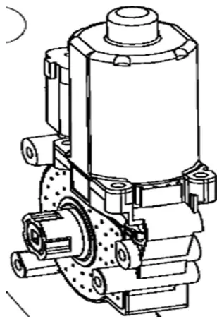
2.3.2 AUTOMATIC SHIFT ACTUATOR
Fig.3 Shift Actuator housing a stepper motor
Automatic shift actuator is monitored by controller. It runs the shift rod which in turn helps in tilting the balls to have no of speed ratios. Contains a small DC motor. Runs on a 12volts battery. Speed Sensor and Integrated Wiring Harness. The Speed Sensor in the CVPT is not a standard Hall Effect sensor. The signal to the Controller varies between 0.7 and 1.4 volts to designate a ferrous bolt passing by the sensor.
2.3.3 CONTROLLER
provided on the Controller.
Port 1: Positive & Negative Power Leads – Provided bare for the developer to use their preferred connection. The system is designed to operate on 12 to 48 Volts DC. While some protection is provided, please note that the Controller may be permanently damaged by reverse polarity.
Port 2: Mini USB used for communicating connector -
Connector between a PC and the Controller, including Shift Table and Configuration Table send and receive functions.
Port 3: HDR1 Main Wiring Harness connector – Primary
connection for operation of the CVP Developer Kit. This allows the Controller to receive Vehicle Speed and Shift Position information, as well as command and power the Shift Actuator.
Port 4: HDR2 Display / Mode Wiring Pigtail connector – Can accommodate a user-supplied Mode Switch.
Port 5:HDR4 Shift Reference Wiring Pigtail connector – Can accommodate a reference voltage signal for manual shifting.
2.3.4 HALL EFFECT SENSOR
A Hall effect sensor is a transducer that varies its output voltage in response to a magnetic field. Hall effect sensors are used for proximity switching, positioning, speed detection, and current sensing applications. In its simplest form, the sensor operates as an analogue transducer, directly returning a voltage. With a known magnetic field, its distance from the Hall plate can be determined. Using groups of sensors, the relative position of the magnet can be deduced. Electricity carried through a conductor will produce a magnetic field that varies with current, and a Hall sensor can be used to measure the current without interrupting the circuit. Typically, the sensor is integrated with a wound core or permanent magnet that surrounds the conductor to be measured. Frequently, a Hall sensor is combined with circuitry that allows the device to act in a digital (on/off) mode, and may be called a switch in this configuration
3 HUB ASSEMBLY
.
3.1 DESIGN ASPECTS OF SPOKE LENGTH:
When building a bicycle wheel, the spokes must have the correct length, otherwise there may not be enough threads engaged, producing a weaker wheel, or they may protrude through the rim and possibly puncture the inner tube. For bicycle spokes, the spoke length is defined from the flange seat to the thread tip. For spokes with bent ends, the nominal spoke length does not include the width of the spoke at the bent end.
Where
l = length of the spoke (mm)
d= spoke hole circle radius of the hub (mm)
r2 = nipple seat radius, equal to half the ERD mm, r3 = radius of spoke holes in the flange mm,
m = number of spokes to be used for one side of the wheel, k = number of crossings per spoke,
a = 360° k/m,
Specifications we used are:
Since the hub is of 36 holes,
2mm diameter and 20.4cm length spokes are considered.
One cross alignment is done.
3.2 DESIGN CALCULATIONS
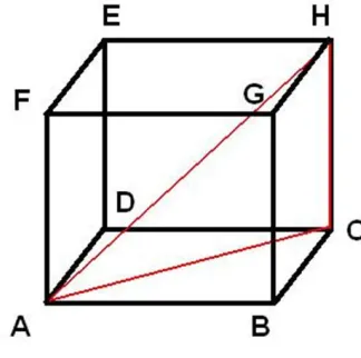
Derivation of the equation for calculating spoke length The spoke length formula computes the length of the space diagonal of an imaginary rectangular box. Imagine holding a wheel in front such that a nipple is at the top. Look at the wheel from along the axis. The spoke through the top hole is now a diagonal of the imaginary box. Equivalently, the law of cosines may be used to first compute the length of the spoke as projected on the wheel's plane (as illustrated in the diagram), followed by an application of the Pythagorean theorem.
Firstfor finding the length of the space diagonal Let length of side AB= p
length of side BC=q length of side GB=r
In triangle ABC, length of AC is given by AC2= AB2+BC2
= p2+q2
279
= p2+q2+r2
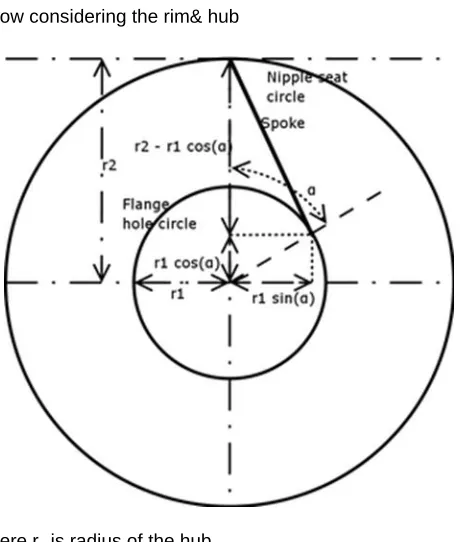
Now considering the rim& hub
Here r1 is radius of the hub
r2 is radius of the rim a is the angle between the radius to a
nipple hole in the rim to which a spoke is attached and the radius to the flange hole holding the spoke.
a= 360*k/m
k is number of crossings per spoke
m is number of spokes to be used for one side of the wheel d is the depth(width) of the hub
r3 is radius of the spoke hole on hub
Using the concepts of finding the length of space diagonal & Pythagorean theorem length of the spoke can be calculated as
l2= d2+(r1sin a) 2
+(r2-r1cos a) 2
= d2+r1 2
+r2 2
-2r1r2 cos a
But the above equation includes the radius of the spoke hole (r3) in the hub which is to be removed. Therefore the above
equation is modified as
Shift Position:
Shift Position = A * ln (Speed Ratio) + B
For initial operation, the following values can be used: A = 731
B = 539
Vehicle speed calculation without CVPT drive train:
Input sprocket teeth (t1): 44
Output sprocket teeth (t2): 18
Speed Ratio = output speed(N2)/input speed(N1) = 1/Gear
Ratio = t1/t2
[Gear Ratio = t2/t1 ]
N2/N1 =t1/t2 = 44/18 = 2.44 N2= 2.44* N1
4 RESULTS
TABLE 1
Output Speed of the bicycle at different input speeds
Without CVPT/
ordinary bicycle Input Speed With CVPT
Source/input
RPM In kmph
Output speed in kmph
Output speed in RPM
0 0 0 0
35.7 8.93 8.51 82
37.5 9.40 9.98 97
40.27 10.09 11.59 112.7
43.1 10.81 13.84 134.6
51.06 12.78 17.31 168.5
59.76 14.97 21.95 213.6
69.06 17.43 27.49 267
70.27 17.61 29.67 288.7
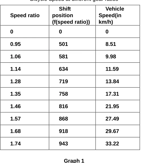
TABLE 2
Bicycle Speed at different gear ratios
Graph 1
Speed curve with and without the transmisiion system
Graph 2
Vehicle speed with respect to shift position
4.1DISCUSSIONOFRESULTS
Spoke length used for our work has been obtained from the expression used and found to be 20.4 cm. Varying the source/input speed, the output speed of the bicycle without CVPT and with CVPT has been obtained and tabulated (Table-1). A graph (graph-1) has been plotted for the values obtained and it has been observed that output speed of the bicycle without CVPT is linearly proportional to the input speed, however for the bicycle with CVPT it has been observed that initially the output speed was lower than the output speed of the bicycle without CVPT and then gradually increased From the obtained speed ratios shift position values are calculated and tabulated (Table-2). It has been observed that the graph (Graph-2) plotted between shift position and vehicle speed is varying continuously. It has been observed that the maximum output speed for vehicle without CVPT is 18.99kmph however the maximum output speed for vehicle with CVPT is 33.21kmph for the same source input.
5 CONCLUSION
In the project work, from the results obtained it has been confirmed that a vehicle with a CVPT drivetrain has a much broader gear ratio range when compared to a bicycle without a CVPT drivetrain and accordingly an advantage of availability of higher speeds achieved with ease.
ACKNOWLEDGEMNT
Authors acknowledge the support offered by Dr. Chris Vasilotis from Fallbrook Technologies.The authors would also like to thank Prof. R Ravinder Rao from KITS,Warangal for his help.
REFERENCES:
[1]. Dr Ben McGarry, ―Engineering assessment of IVT concept,‖ DBG:BM:208320, A division of Gilmore Engineers Pty Ltd, Research and Development [2]. Zhijian Lu, ―Acceleration Simulation of a Vehicle
with a Continuously Variable Power Split Transmission.‖ 1998
[3]. Chao-Hsu Yao, ―Automotive Transmissions: Efficiently Transferring Power from Engine to Wheels‖ Discovery Guides, January 2008.
[4]. Jovan DORIĆ, Ivan KLINAR& Marko DORIĆ: ―ONE APPROACH FOR MODELLING INTERMITTENT MOTION MECHANISM WITH NON CIRCULAR GEARS‖, machine design, Vol.3(2011) No.2, ISSN 1821-1259 pp. 121-126. [5]. Long-Chang Hsieh and Tzu-Hsia Chen, ―The
Kinematic Design of Automatic Gear Transmissions for Bicycles,‖ Engineering Letters, 16:3, EL_16_3_17.
[6]. AHMAD MUSTAKIM BIN MOHD RUSLI, ―Comparison of Automatic And CVT Transmission For a Car,‖ UNIVERSITY MALAYSIA PAHANG, 2010
[7]. M. Savage, K.L. Rubadeux, H.H.Coe, ―Effects of Planetary Gear Ratio on Mean Service Life.‖ Prepared for the Seventh International Power
Speed ratio
Shift position (f(speed ratio))
Vehicle Speed(in km/h)
0 0 0
0.95 501 8.51
1.06 581 9.98
1.14 634 11.59
1.28 719 13.84
1.35 758 17.31
1.46 816 21.95
1.57 868 27.49
1.68 918 29.67
281
Transmission and Gearing Conference sponsored by the American Society of Mechanical Engineers San Diego, California, October 6-9,1996.
[8]. Ya-Li Feng, Yi-Ting Kang, Wen-Ming Zhang, and Jie Zhang ―STEADY-STATE CHARACTERISTICS ANALYSIS OF DEEP-SEA RUNNING MECHANISM WITH PLANETARY GEAR WHEEL‖ Journal of Marine Science and Technology, Vol. 18, No. 5, pp. 780-784 (2010).
[9]. Vijaya Kumar Ambarisha, Robert G. Parker, ―Nonlinear dynamics of planetary gears using analytical and finite element models,‖ Journal of Sound and Vibration 302 (2007) 577–595.
[10].G. J. Cheon, D. H. Lee, H.T. Ryu, J. H. Kim, D.C.Han, ―A Study on The Dynamic Characteristics of an Epicyclic Gear Train With Journal Bearing‖, 99PC-21